 Small batches, high standards. Our rapid prototyping service makes validation faster and easier —

Custom CNC Cutting Decoded: From First Design To Finished Part
What Custom CNC Cutting Actually Means for Your Projects
Ever wondered how manufacturers create parts that fit together perfectly every single time? The answer often lies in custom CNC cutting—a technology that bridges the gap between your digital designs and physical precision parts.
CNC stands for Computer Numerical Control, a process where pre-programmed software directs machinery to cut, shape, and form raw materials into finished components with exceptional accuracy.
Unlike mass-produced, off-the-shelf components, custom CNC cutting delivers parts tailored specifically to your project requirements. Whether you need a single prototype or thousands of identical pieces, this technology transforms your specifications into reality with remarkable consistency.
From Digital Design to Physical Reality
Imagine sketching a complex part on your computer and watching it materialize from a solid block of aluminum hours later. That's essentially what happens with CNC machine cutting. The journey begins with Computer-Aided Design (CAD) software, where designers create detailed 3D models of the desired part.
Here's where the magic happens: these digital designs get translated into G-code—a specialized programming language that tells the CNC cutting machine exactly how to move, how fast to cut, and where to position its tools. According to Goodwin University's manufacturing resources, the machine's microcomputer receives this customized code through its control unit, executing precise movements based on the programmed specifications.
This precision machining services approach eliminates the guesswork that once defined traditional manufacturing. Every cut follows the exact digital blueprint, whether you're producing the first part or the five-hundredth.
How Computer Control Revolutionizes Cutting Precision
So what is CNC routing, and how does it differ from manual methods? Traditional machining relies heavily on an operator's skill and steady hands. One moment of fatigue or a slight miscalculation can compromise an entire batch of parts.
CNC cutting flips this equation entirely. The computerized control system maintains accuracy typically between 0.0002 to 0.0005 inches—precision that even the most skilled human operator would struggle to match consistently. This repeatability becomes crucial when you need multiple parts that must fit together seamlessly.
The scope of materials that respond well to CNC machining spans impressively wide:
- Metals: Aluminum, steel, titanium, brass, and specialty alloys
- Plastics: Engineering-grade polymers for functional prototypes and production parts
- Wood and composites: From decorative elements to structural components
Industries from aerospace to medical devices rely on this technology precisely because it delivers what standard manufacturing cannot—parts designed around your exact specifications, not the other way around. The difference between ordering a generic component and commissioning a custom-cut part often means the difference between a solution that almost works and one that works perfectly.
Three Core CNC Cutting Methods and When to Use Each
Now that you understand what custom CNC cutting delivers, the next question becomes: which cutting method actually fits your project? The answer depends on your part's geometry, material, and production goals. Let's break down the three core approaches so you can make an informed decision.
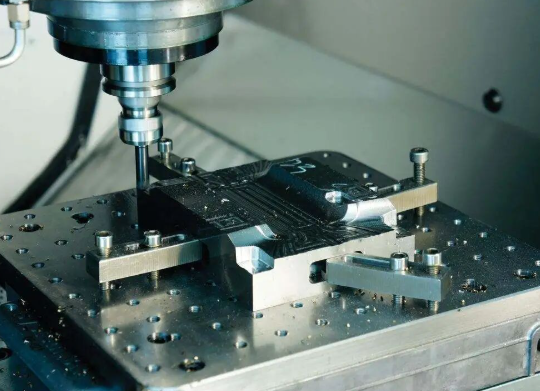
CNC Milling Explained
Picture a rotating cutting tool carving through a stationary block of material—that's CNC milling in action. The workpiece stays fixed while multi-point cutters move along multiple axes to remove material and create your desired shape.
What makes milling particularly versatile? It handles complex three-dimensional geometries that other methods simply cannot touch. According to RapidDirect's machining comparison guide, CNC milling excels at producing components with flat surfaces, slots, pockets, holes, angles, and intricate 3D shapes.
The real decision point comes down to axis capability:
- 3-axis milling: The cutting tool moves along X, Y, and Z axes. Perfect for straightforward parts with simple geometries—think housings, panels, and flat surfaces. These machines cost between $25,000 to $50,000 and require minimal operator training.
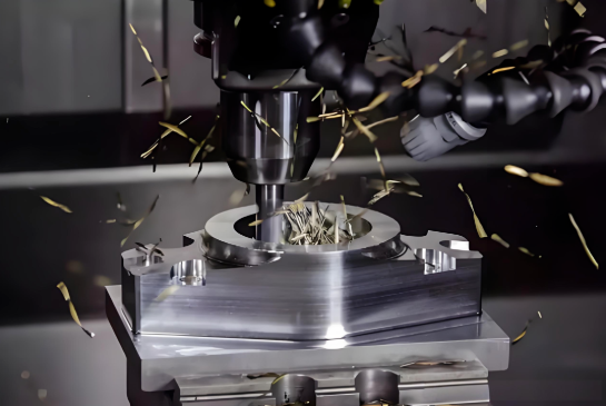
- 5-axis milling: Adds two rotational axes (A and B), allowing the tool to approach workpieces from virtually any angle. This eliminates multiple setups and enables continuous milling of turbine blades, impellers, and aerospace components. The trade-off? Machines range from $80,000 to over $500,000 and demand specialized programming expertise.
When should you choose 5-axis over 3-axis? If your part requires deep cavities, undercuts, or work on multiple sides without repositioning, the efficiency gains often justify the higher cost per part. For simpler geometries, 3-axis delivers excellent results at a fraction of the investment.
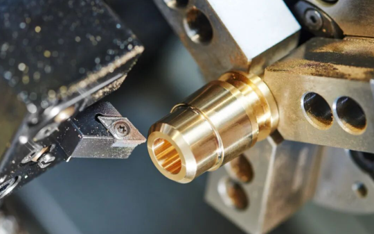
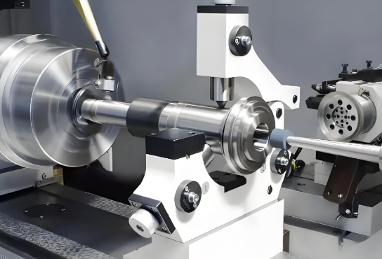
CNC Turning for Cylindrical Components
Here's where the motion reverses entirely. In CNC turning, the workpiece rotates at high speed while a stationary cutting tool shapes its surface. This fundamental difference makes a cnc turning service the go-to choice for anything cylindrical or rotationally symmetrical.
Think shafts, rods, bushings, and pipes—any part that shares a common centerline. According to manufacturing experts at JLCCNC, turning produces these components faster and more efficiently than milling ever could.
The advantages stack up quickly:
- Faster production cycles for round parts
- Lower operational costs compared to milling cylindrical shapes
- Excellent surface finishes on external and internal diameters
- Precise control over diameter and length specifications
The limitation? CNC turning struggles with flat, angular, or asymmetrical features. If your design incorporates significant non-cylindrical elements, you may need a combination of turning and milling operations—or milling alone.
CNC Routing for Sheet Materials
When you need speed on softer materials, cnc routing services offer a compelling solution. CNC routers spin their cutters at extremely high RPMs, making quick work of wood, plastics, foam, and composite sheet materials.
What distinguishes a cnc router cutting service from milling? The machine's lighter frame prioritizes speed over rigidity. This design choice means routers excel at:
- Rapid cutting of large sheet materials
- Signage and decorative panel production
- Furniture components and cabinetry
- Foam prototypes and packaging inserts
However, this speed comes with trade-offs. The lightweight construction generates more vibration during deeper cuts, which can affect precision on demanding applications. For cnc milled parts requiring tight tolerances in hard metals, traditional milling remains the superior choice.
Comparing Methods at a Glance
Choosing between these three approaches becomes clearer when you evaluate your specific requirements against each method's strengths. The following comparison highlights the key decision factors:
| Factor | CNC Milling | CNC Turning | CNC Routing |
|---|---|---|---|
| Best Materials | Metals (aluminum, steel, titanium), engineering plastics | Metals, plastics suitable for cylindrical parts | Wood, plastics, foam, soft composites |
| Typical Tolerances | ±0.001" to ±0.005" (tighter with 5-axis) | ±0.001" to ±0.005" | ±0.005" to ±0.010" |
| Ideal Part Geometries | Complex 3D shapes, pockets, slots, multi-sided features | Cylindrical, rotationally symmetrical parts | 2D profiles, sheet-based components |
| Common Applications | Aerospace components, molds, mechanical assemblies | Shafts, rods, bushings, pipes, fasteners | Signs, panels, furniture, foam prototypes |
| Production Suitability | Prototypes through high-volume production | Highly efficient for production runs | Best for quick turnaround on soft materials |
Matching Methods to Your Project Type
For prototyping, flexibility often matters more than per-unit cost. CNC milling—particularly 3-axis—delivers the versatility to iterate through design changes without requiring specialized tooling. You can machine a concept, test it, refine your CAD model, and produce an updated version within days.
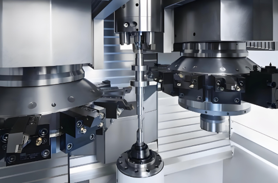
Production runs shift the calculus. When you need hundreds or thousands of machined parts with consistent quality, the initial setup investment pays dividends. CNC turning becomes exceptionally cost-effective for cylindrical components at volume, while 5-axis milling justifies its complexity for intricate parts that would otherwise require multiple operations.
Simple geometries rarely need sophisticated equipment. A basic bracket or mounting plate machines beautifully on 3-axis equipment, keeping your costs manageable. Reserve the advanced capabilities—and their associated premiums—for parts that genuinely demand them.
Understanding these distinctions positions you to have more productive conversations with service providers and ensures your project lands on the right equipment from the start. The next consideration? Selecting materials that complement your chosen cutting method.
Material Selection Guide for Optimal CNC Cutting Results
You've identified your cutting method—now comes an equally critical decision: what material should you cut? The relationship between material choice and project success runs deeper than most realize. Your selection directly influences tooling requirements, machining speeds, achievable surface finishes, and ultimately, your budget.
Think of it this way: the same CNC program running on identical equipment will produce dramatically different results depending on whether you're cutting aluminum or stainless steel. Understanding these distinctions helps you balance performance requirements against practical constraints.
Metals That Machine Beautifully
When strength, durability, and thermal resistance top your requirements list, metals deliver. But "metal" encompasses an enormous range of options, each bringing distinct machining characteristics to your project.
- Aluminum alloys — The workhorses of custom CNC cutting. According to Hubs' material selection guide, aluminum offers an excellent strength-to-weight ratio, high thermal and electrical conductivity, and natural corrosion protection. These alloys machine easily and cost-efficiently in bulk, often making them the most economical metal option. Aluminum 6061 serves as the general-purpose choice, while 7075 delivers aerospace-grade strength comparable to some steels.
- Stainless steel alloys — Choose these when corrosion resistance and high-temperature performance matter. The 304 grade handles most environmental conditions beautifully, while 316 steps up for harsher chemical or marine environments. Expect slower cutting speeds and increased tool wear compared to aluminum, but the durability often justifies the trade-off.
- Mild and alloy steels — Cost-effective options when ultimate corrosion resistance isn't critical. CNCCookbook's machining guide notes that 1018 steel offers excellent machinability and weldability, making it popular for jigs, fixtures, and high-volume screw machine parts. Alloy steels like 4140 add chromium and molybdenum for improved mechanical properties.
- Bronze and brass — These copper alloys shine where low friction, electrical conductivity, or decorative appearance matter. CNC machining bronze produces excellent results thanks to the material's natural lubricity. Brass C36000, specifically, ranks among the most easily machinable metals available—ideal for high-volume applications where cycle time impacts cost significantly. When you machine bronze components, expect clean chip formation and minimal tool wear.
- Tool steels — Reserved for applications demanding exceptional hardness and wear resistance. D2 and A2 grades machine in their annealed state, then undergo heat treatment to achieve final hardness. These specialty materials require careful toolpath planning and appropriate cutting parameters.
Engineering Plastics and Their Unique Requirements
Plastics introduce machining considerations that metals don't present. Heat management becomes paramount—cut too aggressively, and the material melts rather than chips cleanly. Yet plastics offer compelling advantages: lighter weight, natural corrosion resistance, lower material costs, and generally better machinability than metals.
According to Komacut's plastic selection guide, plastics require less cutting force and can run at higher speeds, reducing tool wear and production time. However, temperature sensitivity demands attention to feed rates and cooling strategies.
- Delrin plastic (POM/Acetal) — The standout performer for precision plastic parts. This delrin material offers the highest machinability among plastics, exceptional dimensional stability at elevated temperatures, and very low water absorption. When your design demands tight tolerances, high stiffness, and low friction, delrin plastic consistently delivers. It's often the first choice for gears, bushings, and precision mechanical components.
- Nylon for machining — An engineering thermoplastic prized for impact strength and chemical resistance. Machining nylon works well for functional prototypes and production parts requiring toughness. One consideration: nylon absorbs moisture, which can affect dimensional stability. Plan for this characteristic in humidity-variable environments.
- Polycarbonate — Exceptional impact strength—better than ABS—combined with optical clarity when transparency matters. This material machines well for fluidic devices, protective covers, and automotive glazing applications.
- ABS — A cost-effective thermoplastic with good mechanical properties and excellent impact strength. CNC machined ABS parts frequently serve as prototypes before transitioning to injection molding for volume production.
- PEEK — The premium choice when extreme conditions demand it. This high-performance thermoplastic maintains mechanical properties across wide temperature ranges and resists most chemicals. Medical-grade PEEK even enables biomedical applications. The trade-off? Significantly higher material cost than standard engineering plastics.
Wood and Composite Considerations
Wood and composite materials typically pair with CNC routing rather than milling, though the principles of material selection still apply. These materials present unique chip formation characteristics—wood fibers tear rather than shear like metals, while composites may contain abrasive reinforcements that accelerate tool wear.
- Hardwoods — Dense species like oak, maple, and walnut produce cleaner cuts but require slower feed rates. Grain direction significantly affects surface quality—cutting with the grain yields smoother results than cross-grain passes.
- Softwoods — Pine, cedar, and similar species machine quickly but may exhibit tearout on detailed features. Sharp tooling and appropriate chip loads minimize these issues.
- Plywood and MDF — Engineered sheet goods offer dimensional stability superior to solid wood. MDF machines exceptionally cleanly, making it popular for patterns and prototypes.
- Fiberglass and carbon fiber composites — The reinforcing fibers that provide strength also create abrasive cutting conditions. These materials demand carbide or diamond-coated tools and generate harmful dust requiring proper extraction systems.
How Material Choice Affects Your Project Outcomes
Every material decision cascades through your project in predictable ways. Understanding these relationships helps you optimize the balance between performance, quality, and cost.
Tooling impact: Harder materials wear cutting tools faster. Machining bronze CNC components might allow standard carbide tooling to last through thousands of parts, while the same tooling cutting stainless steel may need replacement after hundreds. This directly affects both tool costs and machine downtime for tool changes.
Speed and cycle time: Softer, more machinable materials like aluminum and bronze cnc parts allow faster feed rates and spindle speeds. A part that takes 15 minutes in aluminum might require 45 minutes in titanium—directly multiplying your per-part cost for labor and machine time.
Surface finish: Some materials naturally produce superior as-machined finishes. Brass and bronze yield excellent surface quality with minimal effort, while certain stainless grades may require secondary finishing operations to achieve comparable results.
Cost considerations: Raw material price represents just one factor. A cheaper material that machines slowly, wears tools quickly, or requires extensive finishing may cost more overall than a premium material that processes efficiently.
Armed with this material knowledge, you're positioned to select options that serve your functional requirements without overlooking the practical realities of CNC production. The next step? Ensuring your design translates smoothly from CAD file to finished part.
Designing Parts That CNC Machines Love to Cut
You've selected your cutting method and chosen your material. Now comes the moment where many projects either accelerate toward success or stumble into costly revisions: translating your design into something a CNC machine can actually produce efficiently.
Design for manufacturability (DFM) isn't about limiting your creativity—it's about understanding how specific design choices ripple through every subsequent manufacturing step. According to Modus Advanced's engineering guide, effective DFM implementation can reduce manufacturing costs by 15-40% and cut lead times by 25-60% compared to non-optimized designs.
What seems like a minor design decision—an unnecessarily tight tolerance here, a sharp internal corner there—can transform a straightforward CNC machining operation into a complex, time-intensive process that delays your project by weeks.
File Formats and Design Software Compatibility
Before discussing geometric features, let's address the foundation: getting your design files into a format CNC machines can interpret. Most service providers accept standard CAD formats, but understanding the options helps you maintain design intent through the manufacturing process.
Common file formats for cnc machining parts include:
- STEP (.stp, .step) — The universal standard for 3D CAD data exchange. STEP files preserve geometric accuracy and transfer cleanly between different software platforms, making them the preferred choice for most CNC service providers.
- IGES (.igs, .iges) — An older format still widely supported. IGES handles complex surfaces well but may occasionally introduce translation errors between systems.
- Native CAD formats — SolidWorks (.sldprt), Autodesk Inventor (.ipt), and similar proprietary formats work when your provider uses matching software. Otherwise, export to STEP for reliability.
- DXF/DWG — Essential for 2D profiles, particularly for CNC routing and laser cutting applications.
One critical consideration: establish whether the CAD model or the engineering drawing takes precedence when discrepancies exist. Clear documentation prevents costly misunderstandings during primary machining operations.
Critical Design Features That Affect Machinability
Certain geometric features directly impact how efficiently—and economically—your parts can be produced. Understanding these relationships empowers you to make informed trade-offs between design ideals and manufacturing realities.
Wall thickness minimums: Thinner walls are less stiff and more susceptible to bending, breaking, and warping during machining. According to Geomiq's design optimization guide, minimum recommended wall thickness is 0.8 mm for metals and 1.5 mm for plastics. Maintaining a width-to-height ratio of 3:1 for unsupported walls ensures stability during cutting operations.
Internal corner radii: Here's a fundamental constraint many designers overlook—CNC cutting tools are cylindrical, which means they physically cannot create perfectly sharp internal corners. Every inside corner will have a radius equal to at least the tool's radius. Specifying a 0.030" (0.76mm) minimum radius allows standard tooling compatibility and can reduce programming time by 50-100% compared to demanding near-sharp corners.
Hole depth-to-diameter ratios: Deep, narrow holes challenge even the best cutting tools. Standard drill bits machine most efficiently when hole depth doesn't exceed 3-4 times the diameter. Beyond six times the diameter, expect increased costs due to specialized tooling, slower feed rates, and chip evacuation challenges.
Undercuts and internal features: Features that standard tools cannot reach from above—like internal channels with curved paths or T-slots—require specialized tooling, multiple setups, or alternative processes entirely. Question whether these features truly serve functional purposes before including them.
Feature orientation: Parts requiring five-axis machining cost 300-600% more than those manageable on three-axis equipment. Aligning features with X, Y, and Z axes whenever possible dramatically reduces complexity. Reserve angled features for applications where they're genuinely necessary.
Tolerance Specifications: When Tight Really Matters
Over-tolerancing ranks among the most common—and costly—design mistakes in custom machined parts. While CNC machines can achieve impressive precision, specifying tighter tolerances than necessary inflates costs without improving function.
For standard CNC machining, ±0.005" (±0.13mm) provides exceptional precision for the vast majority of mechanical components. Tighter tolerances like ±0.002" increase costs by 25-50% and should only be specified when functionally necessary.
According to Modus Advanced's tolerance guide, extremely tight tolerances below ±0.001" introduce manufacturing variables typically ignored in standard operations—temperature control, machine warm-up procedures, and stress relief operations become critical factors that significantly extend timelines.
When should you specify tighter tolerances?
- Mating surfaces where precise fit affects function
- Moving parts with specific clearance requirements
- Safety-critical components under regulatory requirements
- Assemblies where accumulated tolerances could affect overall performance
For structural components, housings, and mounting brackets, standard tolerances typically perform their intended function perfectly. Thoughtful engineering often accommodates standard tolerances through smart design choices—like incorporating appropriate clearances—rather than demanding tighter manufacturing requirements.
Common Design Mistakes to Avoid
Learning from others' missteps saves both time and money. These frequently encountered issues create manufacturing bottlenecks that could easily be prevented during the design phase:
- Sharp internal corners: Requires specialized small tooling, multiple setups, and adds 50-100% to programming time per feature. Always add radii to inside corners.
- Knife edges: Where two surfaces meet at extremely acute angles, fragile features result that are problematic for machining and part durability. Add small outside fillets (0.005-0.015") to eliminate these issues.
- Complex decorative curves: Aesthetic features without functional purpose can add 200-400% to machining time. Question every curve: does it serve a specific functional purpose?
- Non-standard hole sizes: Standard drill bits efficiently and accurately create standard hole sizes. Non-standard dimensions require progressive end milling, increasing time and cost.
- Excessive thread depth: Thread strength typically resides in the first few threads. Limit depths to maximum three times the hole diameter.
- Cast-optimized prototypes: Draft angles common in cast designs require specialized tooling for machined prototypes. Create separate design versions optimized for each manufacturing method.
Your Design Preparation Checklist
Before submitting your design for quoting or production, walk through this sequence to catch potential issues early—when changes cost hours rather than weeks:
- Export clean file formats: Save as STEP for universal compatibility, and include 2D drawings for critical dimensions and tolerances.
- Verify wall thicknesses: Confirm minimum 0.8mm for metals, 1.5mm for plastics, with appropriate width-to-height ratios for unsupported sections.
- Add internal corner radii: Specify at least 0.030" radius on inside corners—larger where your design permits.
- Review hole specifications: Use standard drill sizes, keep depth-to-diameter ratios under 4:1 where possible, and ensure adequate wall clearance for tapped holes.
- Evaluate tolerance requirements: Apply tight tolerances only to features requiring them. Use ±0.005" as baseline for non-critical dimensions.
- Simplify where function permits: Eliminate purely aesthetic complexity. Use consistent radii rather than varying curves.
- Check feature accessibility: Ensure all features can be reached with standard tooling without requiring five-axis operations unless truly necessary.
- Document datum structure: Reference critical features from nearby, accessible datum surfaces to simplify fixturing and measurement.
How Design Complexity Impacts Your Bottom Line
Every design decision carries cost and timeline implications. Understanding these relationships helps you make informed trade-offs during cnc prototyping and production planning.
Complex geometries requiring five-axis machining might add 200-500% to lead times compared to three-axis-friendly designs. Specifying tolerances tighter than ±0.002" can increase inspection time by 100-400% when profile measurements replace simple dimensional checks. Features requiring specialized tooling may add days for tool procurement before machining even begins.
The good news? These impacts compound in reverse when you optimize for manufacturability. Cnc machined parts designed with these principles in mind move through programming, setup, machining, and inspection faster at every stage. The cumulative effect often exceeds the sum of individual optimizations.
With your design optimized for manufacturing, the next decision awaits: determining whether CNC cutting is truly the right technology for your specific application—or whether alternative methods might serve you better.
Choosing the Right Cutting Technology for Your Application
Your design is optimized and your material selected—but here's a question worth pausing on: is custom CNC cutting actually the best method for your project? Sometimes the answer is a resounding yes. Other times, laser cutting, waterjet, or even 3D printing might serve you better.
Making this decision wisely can save you thousands of dollars and weeks of lead time. Making it poorly? That's when projects stall, budgets balloon, and frustration sets in.
Let's walk through the decision-making framework that separates informed buyers from those learning expensive lessons the hard way.
CNC Cutting vs Laser Cutting vs Waterjet
Each cutting technology brings distinct strengths to the table. According to SendCutSend's fabrication guide, material selection, size, tolerance requirements, and post-processing needs all factor into choosing the ideal method.
CNC cutting utilizes computer-controlled tools to physically remove material from your workpiece. Metal cnc machines excel when you need three-dimensional features, tight tolerances, or work with thicker stock. The mechanical cutting action produces clean edges on metals, plastics, and wood—though it may generate heat depending on cutting parameters.
Laser cutting employs a high-powered laser beam to melt, burn, or vaporize material along preprogrammed paths. Capable of cutting upwards of 2,500 inches per minute, laser cutting often represents the fastest and most economical option for 2D profiles. It excels at intricate designs with small features and minimizes heat-affected zones in detailed work.
Waterjet cutting uses an extremely high-pressure water stream mixed with abrasive garnet to cut through virtually any material without heat. This eliminates thermal distortion entirely—making it ideal for aerospace applications where regulations prohibit any heat-affected zones on aircraft parts.
The following comparison helps clarify when each method shines:
| Factor | CNC Cutting | Laser Cutting | Waterjet Cutting |
|---|---|---|---|
| Material Compatibility | Metals, plastics, wood, composites—excellent aluminum machining capabilities | Most metals up to 1/2"; not suitable for PVC or highly flammable materials | Virtually any material including glass, carbon fiber, and thick metals |
| Thickness Capabilities | Handles thick stock well; suited for 3D features at any depth | Optimal for sheet materials; striations appear in thicker cuts | Cuts thick materials cleanly; historically used for large billets |
| Edge Quality | Excellent with proper tooling; may require deburring | Clean cuts on thinner stock; some dross possible on thicker materials | Superior surface finish; eliminates burrs and dross entirely |
| Typical Tolerances | ±0.001" to ±0.005" | Tight tolerances; material-dependent | ±0.009" typical |
| Heat-Affected Zone | Minimal with proper feeds and speeds | Small HAZ; minimized by fast cutting speed | None—cold cutting process |
| Cost Factors | Higher setup costs; economical for 3D parts and production runs | Often fastest and most affordable for 2D profiles | Slower than laser; premium for difficult composites |
One practical consideration often overlooked: CNC cutting handles 3D features that laser and waterjet simply cannot produce. If your part requires pockets, threaded holes, or complex contoured surfaces, metal cnc machining becomes your only option among these three.
When 3D Printing Makes More Sense
Sometimes neither cutting nor traditional machining represents the optimal path. According to UltiMaker's manufacturing comparison, 3D printing excels in specific scenarios where its additive approach outperforms subtractive methods.
Consider 3D printing when your project involves:
- Complex internal structures: Lattices, channels, and hollow geometries that would be impossible to machine
- Low quantities (1-10 parts): The economics favor additive manufacturing at small volumes
- Rapid design iteration: Changing designs requires only a new file, not reprogramming and retooling
- Organic shapes: Curved, flowing geometries that would require extensive 5-axis machining
However, traditional CNC machining maintains clear advantages for:
- Precision requirements: CNC achieves tolerances as tight as ±0.025mm versus ±0.1mm to ±0.5mm for most 3D printing
- Surface finish: CNC produces surface roughness values as low as 0.8 μm compared to around 15 μm for printed parts
- Material strength: Machined parts maintain full mechanical properties of the source material
- Production volumes: Beyond 10-100 parts, CNC becomes increasingly cost-competitive
The break-even point varies by application, but the pattern holds: 3D printing wins for complexity and low volumes, while CNC excels for precision, strength, and scale.
Volume Considerations from Prototype to Production
Your project lifecycle significantly influences which technology delivers the best value at each stage. According to Avid Product Development's scaling guide, rushing from prototype to production without proper preparation leads to wasted money, costly redesigns, and supply chain headaches.
Concept and early prototyping: At this stage, speed and flexibility matter more than per-unit cost. 3D printing often makes sense for initial form and fit testing. CNC prototyping works well when you need functional prototypes in production-representative materials—testing a part in actual aluminum rather than plastic reveals issues that material substitutes mask.
Design validation: Before committing to production tooling, validate your design with small batches. CNC cutting shines here because parts match final production intent. This catches design flaws while changes remain affordable.
Pilot runs (50-500 units): Bridge the gap between prototype and mass production. These runs evaluate manufacturability, assembly workflows, and supply chain readiness. Discovering packaging issues or assembly bottlenecks during a 500-unit pilot costs far less than finding them after launching full production.
Production scaling: As volumes climb into the thousands, CNC cutting economics improve dramatically. Setup costs amortize across more parts, and optimized programs run efficiently. For cylindrical components, CNC turning becomes exceptionally cost-effective at volume.
The Complete Project Lifecycle
Thinking beyond just cutting reveals additional considerations that affect your technology choice:
Post-processing requirements: Some cutting methods create parts ready for use; others require secondary operations. Laser-cut metals may need deburring. CNC-routed parts often have small fixture tabs requiring hand finishing. Waterjet parts typically need minimal cleanup.
Finishing options: Consider what happens after cutting. Anodizing aluminum? Powder coating steel? Certain cutting methods integrate better with specific finishing processes. Heat-affected zones from laser cutting can occasionally interfere with subsequent surface treatments.
Assembly integration: How will your cut parts interact with other components? CNC cutting's ability to add threaded holes, counterbores, and precise mating surfaces often eliminates secondary operations that laser or waterjet parts would require.
The right technology choice considers your entire project—from first concept through final assembly. Making that decision thoughtfully positions you for success; making it hastily creates problems that compound at every subsequent stage.
Even with the optimal technology selected, challenges can arise during production. Understanding common CNC cutting problems—and how to prevent them—keeps your project on track.
Avoiding Common CNC Cutting Problems Before They Happen
You've selected the right cutting technology, optimized your design, and chosen appropriate materials. Yet even well-planned projects can encounter production issues that compromise quality or extend timelines. The difference between frustrating setbacks and smooth production often comes down to anticipating problems before they occur.
Understanding what causes common CNC cuts to go wrong—and how to prevent these issues—transforms you from a passive customer into an informed partner in the manufacturing process. Let's examine the challenges that derail projects and the strategies that keep them on track.
Surface Finish Issues and Their Root Causes
When your finished part arrives with rough textures, visible lines, or an uneven finish, something went wrong during the cutting process. According to Elephant CNC's troubleshooting guide, poor surface finish rarely has a single cause—it typically results from the interaction of several factors working together.
Common surface finish problems and their solutions include:
- Chatter marks: Those wavy, regular patterns indicate vibration during cutting. The fix? Reduce tool overhang, secure the workpiece more rigidly, or adjust spindle speeds to avoid resonant frequencies. Sometimes simply switching to a tool with different flute geometry dampens the vibration entirely.
- Tool marks and ridges: Visible lines from tool interaction suggest worn cutting tools or improper toolpath overlap. Sharp, high-quality tooling combined with appropriate step-over values produces smoother results.
- Burn marks: Dark or discolored patches signal overheating during machining. Reducing cutting speed, increasing feed rate, or improving coolant flow addresses the root cause. For materials like titanium that conduct heat poorly, managing thermal buildup becomes especially critical.
- Rough texture: Often stems from incorrect feed rates—going too slow causes rubbing instead of clean cutting, while excessive speed generates heat and friction. Matching parameters to your specific material restores smooth finishes.
The underlying principle? Surface finish problems almost always trace back to tool condition, cutting parameters, or workholding stability. Address these fundamentals, and most finish issues disappear.
Dimensional Accuracy Problems
Few things frustrate project timelines more than parts that don't meet dimensional specifications. A slight deviation might seem minor—until those parts fail to assemble correctly or get rejected during inspection.
According to 3ERP's defect analysis, dimensional inaccuracies occur when machined parts don't adhere to specified dimensions, leading to issues in fit, function, or both. The causes span mechanical, thermal, and programming domains:
- Tool deflection: When cutting forces push the tool away from its intended path, dimensions suffer. Longer tools with smaller diameters deflect more readily. Using the shortest, stiffest tool possible for each operation minimizes this effect.
- Thermal distortion: Metals expand when exposed to cutting heat. If parts heat up significantly during machining, final measurements may differ once the material cools. Managing heat through proper coolant application and appropriate cutting parameters keeps thermal expansion under control.
- Backlash in machine axes: Wear in ball screws or linear guides creates play between movements, causing inconsistent positioning during direction changes. Proper machine maintenance and backlash compensation in control software address this mechanical issue.
- Improper tool offsets: If tool length or diameter offsets aren't set correctly, every cnc cut lands slightly off target. Verifying offsets before production runs prevents systematic errors across entire batches.
Tolerance stack-up presents a particular challenge in multi-operation parts. When a single part requires milling, turning, and secondary operations, small deviations compound at each step. A feature that's 0.002" off after the first operation might be 0.005" off after three operations—potentially pushing cumulative error beyond acceptable limits. Thoughtful process planning, consistent datum structures, and intermediate inspection points catch stack-up issues before they cascade.
Material-Specific Cutting Challenges
Different materials respond uniquely to CNC machining, each presenting specific challenges that require tailored approaches. What works perfectly for aluminum may produce terrible results in polycarbonate or stainless steel.
Plastic-specific issues:
- Melting and gumming: Plastics are temperature-sensitive. CNC polycarbonate and similar materials can melt rather than chip cleanly when cutting parameters generate excessive heat. Faster feed rates, reduced spindle speeds, and adequate chip evacuation prevent thermal damage.
- Stress cracking: Acrylic cnc machining requires particular attention to avoid cracking. Sharp tools, proper feeds and speeds, and sometimes post-machining annealing keep internal stresses from causing fractures.
- Dimensional instability: Some plastics absorb moisture or respond dramatically to temperature changes, affecting final dimensions. Understanding these characteristics—and when to measure parts—prevents out-of-spec rejections.
Metal-specific issues:
- Work hardening: Stainless steels and certain alloys harden during cutting, making subsequent passes more difficult. Maintaining constant chip load and avoiding dwelling in cuts prevents the material from work-hardening ahead of the tool.
- Burr formation: Soft, ductile metals like aluminum produce burrs more readily than harder materials. According to DEK's defect guide, burrs are tiny unwanted edges that appear around corners and edges, affecting both appearance and function. Sharp tooling, proper cutting direction, and sometimes dedicated deburring passes address this issue.
- Built-up edge: When chips adhere to the cutting tool due to high pressure and frictional heat, precision suffers. Using appropriate coatings, maintaining adequate coolant flow, and selecting correct cutting speeds prevent material adhesion.
Prevention Through Process Control
Rather than reacting to problems after they occur, effective manufacturing prevents them through systematic process control. Several strategies dramatically reduce defect rates:
Proper fixturing: Workpiece movement during cutting causes dimensional errors, surface finish problems, and even tool breakage. Rigid, well-designed workholding keeps material exactly where it belongs throughout operations. For thin-walled or flexible parts, additional support prevents deflection under cutting forces.
Optimized feed rates and speeds: Every material-tool combination has a sweet spot where cutting occurs efficiently without excessive heat, vibration, or tool wear. Operating within these parameters—neither too aggressive nor too conservative—produces consistent results.
Strategic toolpath planning: How the tool approaches and exits the material matters as much as how it cuts. Climb milling generally produces better surface finishes than conventional milling. Gradual tool engagement reduces shock loading. Consistent chip loads maintain stable cutting conditions.
Tool condition monitoring: Worn or damaged tools produce defects long before they fail completely. Regular inspection and proactive replacement prevent the gradual quality degradation that leads to rejected parts.
Understanding these common challenges—and their prevention strategies—positions you to evaluate service providers more effectively. The next step? Learning how costs are calculated and what to look for when selecting a manufacturing partner.
Understanding CNC Cutting Costs and Service Provider Selection
You understand the technology, you've optimized your design, and you know which problems to avoid. Now comes a question that directly impacts your budget: how much will custom CNC cutting actually cost—and how do you find a provider who delivers quality without surprises?
Pricing for precision cnc machining services isn't arbitrary, though it can seem opaque to first-time buyers. Every quote reflects a calculation of machine time, materials, labor, and overhead. Understanding these variables helps you interpret quotes intelligently, compare providers fairly, and identify opportunities to reduce costs without sacrificing quality.
What Drives Custom CNC Cutting Costs
When you request a cnc quote online, the numbers you receive aren't pulled from thin air. According to Komacut's machining cost analysis, several interconnected factors determine what you'll pay for each part. Grasping these relationships transforms you from someone who simply accepts quotes to someone who understands—and can optimize—them.
- Material type and usage: Raw material cost represents just the starting point. Harder materials like stainless steel and titanium require more machining time and accelerate tool wear, increasing costs beyond material price alone. Softer materials such as aluminum machine faster and extend tool life, often making them the most economical choice. Plastics typically cost less than metals but require specific handling to prevent heat-related damage.
- Part complexity: Complex designs with intricate features, tight tolerances, and multiple setups demand more programming time, specialized tooling, and careful execution. A simple bracket might machine in minutes; an aerospace component with compound angles could require hours of careful work. According to Komacut's analysis, designs requiring five-axis machining cost significantly more than those achievable on three-axis equipment.
- Tolerance specifications: Standard tolerances (±0.005") work for most applications and keep costs manageable. Tighter specifications require slower cutting speeds, more frequent inspections, and sometimes climate-controlled environments—all adding expense. Only specify tight tolerances where function genuinely demands them.
- Quantity and batch size: Here's where economies of scale become tangible. Setup costs—programming, fixturing, tool installation—spread across more units as quantities increase, dramatically reducing per-part expense. A single prototype might cost ten times more per unit than the same part ordered in quantities of 500.
- Finishing requirements: Post-machining operations like anodizing, powder coating, heat treatment, or precision grinding add cost and lead time. Some finishes require outsourcing to specialized facilities, introducing coordination complexity. Consider which finishes are truly necessary versus merely nice-to-have.
- Material thickness and machining time: Thicker materials require multiple passes to achieve required depths, extending cycle times. Similarly, harder materials necessitate slower feed rates to prevent tool damage, further increasing machining duration—and cost.
Regional labor costs also influence pricing significantly. Shops in high-cost areas face elevated expenses for skilled operators, programmers, and quality personnel. However, proximity to local machine shops can offset price differences through reduced shipping costs and faster communication. When searching for machinist shops near me, weigh geographic convenience against capability and pricing.
Evaluating Service Provider Capabilities
Not all CNC machining providers are created equal. The cheapest quote rarely represents the best value if it comes from a shop lacking the equipment, expertise, or quality systems your project requires. According to 3ERP's provider selection guide, evaluating capabilities thoroughly prevents costly mistakes.
Equipment and technical capabilities: Does the provider have machinery suited to your project? A shop specializing in cnc turning services may lack the five-axis milling capability your complex part requires. Conversely, paying premium rates at a high-capability shop for simple parts wastes money. Match provider capabilities to project requirements.
Certifications matter: Quality management certifications provide objective evidence of a provider's commitment to consistent processes. ISO 9001 certification indicates a documented quality management system covering everything from incoming material inspection to final product verification. For automotive applications, IATF 16949 certification adds industry-specific requirements for defect prevention and continuous improvement. These certifications aren't just wall decorations—they represent systematic approaches to maintaining quality across every order.
Material availability: Can the provider source your required material readily? Delays in material procurement extend lead times and can increase costs. Established custom cnc machining services maintain relationships with material suppliers that newer or smaller operations may lack.
Communication and responsiveness: How quickly do they respond to inquiries? Do they ask clarifying questions that demonstrate understanding of your project? Effective communication throughout the project prevents misunderstandings that cause delays and rework.
Online machining quotes versus consultation: Many providers offer instant online machining quotes—useful for ballpark estimates and simple parts. However, complex projects benefit from direct consultation where experienced engineers review your design, suggest optimizations, and provide accurate pricing based on thorough understanding.
Lead Time Expectations and the Speed-Cost Balance
Time costs money—sometimes directly, sometimes indirectly. Understanding typical lead times helps you plan projects realistically and make informed trade-offs between speed and expense.
Standard lead times for custom CNC cutting typically range from one to four weeks, depending on complexity, quantity, and the provider's current workload. Rush services that compress these timelines command premium pricing, sometimes adding 25-50% to standard rates.
Factors affecting lead time include:
- Design review and programming: Complex parts require more upfront preparation time.
- Material procurement: Common materials are often stocked; specialty alloys may require ordering.
- Machine availability: Shop capacity varies; busy periods extend queues.
- Secondary operations: Finishing, heat treatment, or additional processing adds time.
- Inspection requirements: Comprehensive quality verification takes time but catches problems before shipping.
Planning ahead reduces the need for expensive expedited services. Building adequate lead time into project schedules transforms rush fees into savings.
Statistical Process Control for Production Consistency
For production runs beyond prototyping, consistency matters as much as individual part quality. Statistical Process Control (SPC) provides the methodology that distinguishes reliable production partners from those who simply hope each part turns out well.
SPC involves systematic measurement and analysis of process variables to detect trends before they cause defects. Rather than inspecting every part after completion—and discovering problems too late—SPC monitors critical dimensions during production, enabling real-time corrections.
Providers implementing SPC typically offer:
- Documented control plans identifying critical characteristics and measurement frequency
- Statistical analysis demonstrating process capability (Cpk values)
- Trend monitoring that catches drift before parts go out of specification
- Root cause analysis when deviations occur, preventing recurrence
For high-volume cnc turning services or production runs where consistency directly affects your product quality, asking about SPC implementation separates professional operations from shops relying on final inspection alone.
Getting Accurate Quotes
The information you provide directly affects quote accuracy. Incomplete specifications lead to quotes based on assumptions—which may not match your actual requirements. To receive reliable pricing:
- Provide complete CAD files: STEP format works universally; include 2D drawings for critical dimensions and tolerances.
- Specify material clearly: Generic "aluminum" isn't sufficient—indicate the specific alloy (6061-T6, 7075, etc.).
- Define quantities: Include both immediate needs and potential future volumes to understand scaling opportunities.
- Note critical features: Highlight tolerances, surface finish requirements, and any special considerations.
- Communicate timeline: Required delivery dates affect pricing and feasibility.
- Describe the application: Understanding how parts function helps providers suggest optimizations you might not have considered.
Well-prepared quote requests receive faster, more accurate responses—and demonstrate professionalism that encourages providers to prioritize your project.
With cost factors understood and evaluation criteria established, you're positioned to select a manufacturing partner aligned with your project requirements. The next consideration? Understanding how different industries leverage custom CNC cutting to solve their unique challenges.
Industry Applications Where Custom CNC Cutting Excels
Understanding costs and selecting the right provider matters—but seeing how custom CNC cutting solves real-world challenges across industries brings the technology's value into sharp focus. From engine components traveling at highway speeds to surgical instruments entering human bodies, precision machining enables applications where failure simply isn't an option.
What makes CNC fabrication so universal? The combination of precision, repeatability, and material versatility adapts to wildly different requirements. A chassis bracket and a medical implant share almost nothing in common—except the manufacturing technology that produces both with exacting accuracy.
Let's explore how three demanding industries leverage custom CNC cutting to solve their unique challenges.
Automotive Components and Chassis Assemblies
When 81.5 million cars sell globally in a single year, the manufacturing systems behind them must deliver consistency at extraordinary scale. According to 3ERP's automotive industry analysis, CNC machining has become crucial in the production of high-precision and critical automotive components—from engine blocks to suspension systems.
Why does the automotive sector depend so heavily on this technology? Consider what's at stake: components that must perform flawlessly across temperature extremes, vibration, and years of continuous use. A malfunction in an engine or chassis component doesn't just inconvenience drivers—it creates genuine safety risks.
Key automotive applications include:
- Engine components: Cylinder blocks, cylinder heads, and intake manifolds require tolerances as tight as ±0.001" to ensure proper sealing and performance. CNC milling transforms aluminum alloy blocks into precisely machined engine cores.
- Chassis assemblies: Suspension brackets, steering components, and structural elements demand both precision and durability. These parts must maintain dimensional accuracy under constant stress and vibration.
- Custom metal bushings: These seemingly simple components require exact specifications to control movement and reduce wear in suspension and steering systems.
- Transmission components: Gears, shafts, and housings where swiss machining techniques produce the fine features and tight tolerances these complex assemblies require.
The automotive industry's quality demands have shaped certification standards that distinguish capable manufacturers. IATF 16949 certification specifically addresses automotive supply chain requirements, emphasizing defect prevention, reduction of variation, and continuous improvement.
Companies that manufacture custom metal parts for automotive applications must demonstrate systematic quality control—not just on individual parts, but across entire production processes. This is where Statistical Process Control becomes essential, monitoring critical dimensions throughout production runs rather than relying solely on final inspection.
For automotive projects requiring this level of capability, Shaoyi Metal Technology exemplifies what IATF 16949-certified manufacturing delivers. Their facility scales seamlessly from rapid prototyping to mass production, with lead times as fast as one working day for high-tolerance components. Their expertise in chassis assemblies and custom metal bushings demonstrates the specialized capability that complex automotive applications demand.
Aerospace Precision Requirements
If automotive tolerances seem demanding, aerospace cnc machining takes precision to another level entirely. According to LG Metal Works' aerospace analysis, turbine blades, engine components, and structural brackets demand tolerances as tight as ±0.0005"—significantly tighter than most manufacturing applications require.
What drives these extreme requirements? The consequences of failure. Components operating in flight-critical systems face aerodynamic forces, extreme temperatures, and stress levels that leave zero margin for error. A microscopic dimensional deviation could cascade into catastrophic consequences.
Aerospace applications present unique material challenges as well. Standard aluminum and steel often lack the performance characteristics these demanding environments require. Instead, manufacturers work with:
- Titanium alloys: Exceptional strength-to-weight ratios and heat resistance, but notoriously difficult to machine due to low thermal conductivity and tendency to work-harden.
- Inconel and other nickel superalloys: Maintain mechanical properties at temperatures exceeding 1,000°F, essential for turbine applications.
- Kovar: When thermal expansion matching with glass or ceramics matters—such as in hermetic seals—kovar machining services become essential. This iron-nickel-cobalt alloy requires specialized expertise due to its unique properties.
- Aerospace-grade aluminum: 7075-T6 delivers strength approaching some steels at a fraction of the weight.
Each material presents distinct chip-forming behaviors, thermal expansion characteristics, and tooling requirements. Successful aerospace manufacturing demands both the right equipment and deep expertise in managing these challenging materials.
Quality assurance in aerospace extends beyond dimensional verification. Full material traceability, AS9100D certification, and documented process controls ensure every component meets the stringent requirements governing aviation safety.
Medical Device Manufacturing Standards
Medical machining occupies a unique position where precision intersects with biocompatibility requirements. According to Venttup's industry analysis, CNC machining helps manufacture surgical instruments and implants that meet FDA and ISO standards—requirements that go far beyond dimensional accuracy.
What distinguishes medical device manufacturing from other precision applications?
- Biocompatibility requirements: Materials must not cause adverse reactions when contacting human tissue. This limits options to specific grades of titanium, stainless steel, cobalt-chrome alloys, and medical-grade polymers like PEEK.
- Surface finish criticality: Implant surfaces often require specific textures that promote osseointegration—the biological bonding between bone and implant. Other devices need mirror finishes that minimize bacterial adhesion.
- Miniaturization demands: Surgical instruments and implants frequently feature extremely small, intricate components. Swiss machining techniques excel here, producing tiny precision features that standard CNC approaches cannot achieve.
- Sterilization compatibility: Parts must withstand repeated sterilization cycles without degradation—whether through autoclaving, gamma radiation, or chemical processes.
The regulatory environment adds another layer of complexity. FDA requirements mandate documented design controls, validated manufacturing processes, and complete traceability from raw material through finished device. ISO 13485 certification provides the quality management framework that medical device manufacturers must maintain.
LG Metal Works notes that surgical-grade precision requires specialized materials suited for medical use, including titanium Ti-6Al-4V ELI (extra-low interstitials) for implants, 316L stainless steel for instruments, and PEEK for applications requiring radiolucency—invisibility to X-rays that allows post-surgical imaging without interference.
How Industries Address Common Requirements
Despite their differences, these demanding industries share fundamental requirements that separate capable manufacturers from those who simply own CNC equipment:
- Certification and quality systems: ISO 9001 provides the foundation. Industry-specific certifications—IATF 16949 for automotive, AS9100D for aerospace, ISO 13485 for medical—add specialized requirements that address each sector's unique concerns.
- Material expertise: Understanding how specific alloys behave during machining—thermal expansion, work hardening, chip formation—enables optimized processes that maintain tolerances while maximizing efficiency.
- Traceability systems: From raw material certificates through final inspection records, complete documentation supports quality verification and regulatory compliance.
- Process control: Statistical Process Control distinguishes reactive inspection from proactive quality management, catching drift before it produces defective parts.
- Scalability: The ability to move from prototype through production volumes without sacrificing quality enables product development timelines that competitive markets demand.
Whether your application involves automotive chassis components, aerospace structural elements, or medical instruments, the principles remain consistent: precision manufacturing requires not just capable equipment, but systematic processes that ensure every part meets specification.
Seeing how these industries leverage custom CNC cutting clarifies what's possible—and what questions to ask when evaluating whether a manufacturer can meet your specific requirements. With this foundation established, you're ready to take the final step: preparing your own project for success.
Starting Your Custom CNC Cutting Project the Right Way
You've journeyed from understanding what custom CNC cutting actually means through material selection, design optimization, technology comparisons, troubleshooting strategies, cost considerations, and real-world industry applications. That's substantial ground covered—but knowledge without action remains theoretical.
Now comes the moment to transform what you've learned into tangible results. Whether you're developing a prototype for a new product or scaling toward production volumes, the steps you take next determine whether your project flows smoothly or stumbles into avoidable setbacks.
Let's distill everything into actionable guidance you can implement immediately.
Your Custom CNC Cutting Project Checklist
Moving from concept to finished custom cnc parts requires systematic preparation. This sequence ensures nothing critical gets overlooked:
- Define your requirements clearly: Before contacting any cnc cutting services provider, document exactly what you need. What function must the part perform? What environmental conditions will it face? What tolerances are genuinely necessary versus simply nice-to-have? Answering these questions prevents costly mid-project changes.
- Prepare design files properly: Export your CAD model as a STEP file for universal compatibility. Create 2D drawings that clearly indicate critical dimensions, tolerances, surface finish requirements, and any special callouts. Mark datums explicitly so manufacturers understand your measurement references.
- Select materials thoughtfully: Match material properties to functional requirements—not assumptions about what "should" work. Consider machinability characteristics that affect cost and lead time. When uncertain, consult with potential providers about material alternatives that might serve your application equally well at lower cost.
- Identify potential cnc service providers: Research manufacturers whose capabilities align with your project. For simple parts, local machine shops may offer convenience and fast turnaround. For demanding applications—especially automotive or aerospace—prioritize certified facilities with documented quality systems. If you're searching for cnc cutting near me, balance geographic convenience against the specialized capability your project requires.
- Request and compare quotes: Submit identical specifications to multiple providers. When quotes vary significantly, ask questions—the differences often reveal assumptions that need clarification. The lowest price rarely represents the best value if it comes from a shop lacking appropriate equipment or expertise.
- Evaluate beyond price: Consider communication responsiveness, willingness to suggest improvements, certifications relevant to your industry, and references from similar projects. A cnc service near me offering slightly higher pricing but superior quality systems often delivers better outcomes than distant low-cost alternatives.
- Plan for iteration: Especially for new designs, expect that first articles may reveal opportunities for refinement. Build time and budget for potential revisions rather than assuming perfection on the first attempt.
Taking the Next Step with Confidence
Throughout this guide, you've seen how design decisions cascade through manufacturing processes, how material properties influence machining approaches, and how quality systems separate reliable partners from those who simply own equipment. This knowledge positions you to engage with manufacturers as an informed partner rather than a passive customer.
The cnc service landscape offers tremendous variety—from neighborhood job shops handling straightforward projects to specialized facilities serving the most demanding industries. Your project's requirements determine which type of partner delivers optimal results.
The most successful custom CNC cutting projects balance three interconnected factors: quality that meets functional requirements, cost that fits project economics, and lead time that supports your schedule. Optimizing any single factor at the expense of others creates problems—the goal is finding the right equilibrium for your specific situation.
For automotive and precision metal projects where quality systems genuinely matter, working with IATF 16949-certified manufacturers provides documented assurance that processes meet automotive industry standards. Shaoyi Metal Technology exemplifies this capability, offering SPC-backed quality control that monitors critical dimensions throughout production rather than relying solely on final inspection. Their ability to scale from rapid prototyping to mass production—with lead times as fast as one working day for high-tolerance components—addresses the timeline pressures that competitive markets create.
Whatever your application, the principles remain consistent: define requirements clearly, prepare documentation thoroughly, select partners whose capabilities match your needs, and maintain communication throughout the process. Custom machine work succeeds when both parties understand expectations and work collaboratively toward shared goals.
You now possess the foundational knowledge to navigate the custom CNC cutting landscape effectively. The next step? Apply what you've learned. Prepare your design files, identify potential providers, and request quotes that transform your digital designs into precision-manufactured reality.
Your project awaits—and you're ready to execute it successfully.
Frequently Asked Questions About Custom CNC Cutting
1. How much do CNC cutting services charge?
CNC cutting costs depend on multiple factors including material type, part complexity, tolerance requirements, quantity, and finishing needs. Simple aluminum parts may cost $50-150 for prototypes, while complex multi-axis components in specialty alloys can reach $500+ per unit. Setup costs spread across larger quantities significantly reduce per-part pricing. IATF 16949-certified manufacturers like Shaoyi Metal Technology offer competitive pricing with SPC-backed quality control for production runs.
2. What is the difference between CNC milling and CNC turning?
CNC milling uses rotating cutting tools against a stationary workpiece to create complex 3D shapes, pockets, and multi-sided features. CNC turning rotates the workpiece while stationary tools shape it, making it ideal for cylindrical parts like shafts, rods, and bushings. Choose milling for complex geometries and turning for rotationally symmetrical components—turning typically offers faster production cycles and lower costs for round parts.
3. What materials can be custom CNC cut?
CNC cutting works with metals (aluminum, steel, titanium, brass, bronze), engineering plastics (Delrin, nylon, polycarbonate, PEEK), and wood/composites. Aluminum offers excellent machinability and cost-effectiveness. Stainless steel provides corrosion resistance. Delrin plastic delivers precision for mechanical components. Material choice affects tooling, machining speed, surface finish, and overall project cost.
4. How do I find reliable CNC cutting services near me?
Evaluate providers based on equipment capabilities matching your project needs, relevant certifications (ISO 9001, IATF 16949 for automotive, AS9100D for aerospace), communication responsiveness, and documented quality systems. Request quotes with complete specifications, compare pricing and lead times, and ask about Statistical Process Control implementation. For automotive applications, certified manufacturers ensure consistent quality across production runs.
5. What file formats are needed for CNC cutting orders?
STEP files (.stp, .step) serve as the universal standard for 3D CAD data exchange with excellent geometric accuracy. Include 2D drawings in DXF/DWG format specifying critical dimensions, tolerances, surface finish requirements, and datum references. Native CAD formats (SolidWorks, Inventor) work when providers use matching software. Complete documentation prevents costly misunderstandings during manufacturing.