 Small batches, high standards. Our rapid prototyping service makes validation faster and easier —

Cnc Precision Machining Parts: 9 Critical Factors Your Supplier Won't Mention
What Makes CNC Precision Machining Parts Different
When aircraft components must withstand extreme forces at 40,000 feet or surgical instruments require perfect dimensional accuracy for patient safety, standard manufacturing tolerances simply won't cut it. This is where CNC precision machining parts become indispensable—delivering the accuracy and consistency that critical applications demand.
So what exactly sets these components apart? CNC precision machining parts are manufactured through computer-controlled subtractive processes that remove material from solid workpieces with extraordinary accuracy. Unlike conventional machining, which relies heavily on operator skill and manual adjustments, this technology uses pre-programmed computer instructions to guide cutting tools along precise paths—eliminating human error and achieving repeatability that manual methods simply cannot match.
From Raw Material to Micron-Level Accuracy
Imagine transforming a solid block of aluminum or titanium into a component where every dimension is controlled within thousandths of an inch. That's the reality of precision machined parts production. The process begins with a CAD model that defines exact geometries, tolerances, and surface finishes. CAM software then translates this digital blueprint into G-code instructions that control every movement of the cutting tool.
While conventional CNC machining typically delivers tolerances of ±0.005 inches, precision machined components consistently reach ±0.0005 inches or tighter—with specialized setups achieving ±0.0001 inches. This represents a tenfold improvement in dimensional control.
Precision CNC machining can achieve tolerances as tight as ±0.0005 inches, with specialized techniques reaching 1-5 microns. Industry leaders routinely hold tolerances of 1-3 microns on medical device components where patient safety depends on perfect dimensional accuracy.
The Digital Revolution in Metal Fabrication
What truly separates high-quality precision machined parts from conventionally manufactured components? Three critical factors:
- Computerized Control vs. Human Control: CNC machines follow pre-programmed instructions to the finest detail, eliminating variations caused by operator fatigue, misreadings, or miscalculations
- Exceptional Repeatability: Industrial CNC machinery offers repeatability indices of around ±0.0005 inches, producing exact replicas with minimal error across production runs
- Real-Time Feedback Systems: High-resolution encoders monitor tool position to sub-micron accuracy, detecting and correcting for machine deflection, tool wear, and thermal expansion as they occur
This level of precision machining part control becomes essential when manufacturing components for medical devices, aerospace systems, and defense equipment—applications where lives literally depend on perfect part performance. A precision machined component in a jet engine or surgical instrument cannot afford dimensional variations that might seem negligible in other contexts.
The distinction matters because tighter tolerances translate directly to better-fitting assemblies, improved performance, and enhanced reliability. When you're sourcing these components, understanding this fundamental difference helps you ask the right questions and evaluate suppliers more effectively.
Core Processes Behind High-Tolerance Components
Understanding how CNC machining parts are created gives you a significant advantage when evaluating suppliers and specifying requirements. The precision capabilities you need depend heavily on which machining process produces your components—and not all processes are created equal when tight tolerances are non-negotiable.
At their core, all CNC machining components result from subtractive manufacturing: material is systematically removed from solid stock until the final geometry emerges. But the specific processes used—whether milling, turning, or specialized techniques like Swiss machining—determine what tolerances, surface finishes, and geometries are achievable.
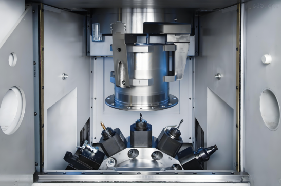
Multi-Axis Milling for Complex Geometries
Think of milling as sculpting with rotating cutting tools. A solid workpiece is secured in a vice while spinning tools carve away material with extraordinary precision. The number of axes determines how complex your precision machining components can become:
- 3-Axis Milling: The cutting tool moves along X, Y, and Z axes—ideal for planar profiles, drilled holes, and threaded features aligned with a single axis. This approach works well for moderately complex CNC milling components but requires multiple setups for features on different faces.
- 4-Axis Milling: Adds a rotary A-axis that rotates around the X-axis, enabling complex geometries like cam lobes, helixes, and angled features in a single setup. This eliminates fixture changeovers and maintains tighter tolerances between features on different sides of the part.
- 5-Axis Milling: Introduces a second rotating axis, providing maximum degrees of freedom. When your precision milling parts demand intricate contours, undercuts, or compound angles, 5-axis machines deliver unmatched capability—though at higher cost.
Why does this matter for your project? Each additional axis reduces the number of setups required. Fewer setups mean less opportunity for alignment errors and better tolerance control across complex part geometries. For aerospace components or medical devices requiring features on multiple faces, 4-axis or 5-axis machining often becomes essential rather than optional.
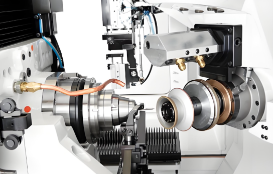
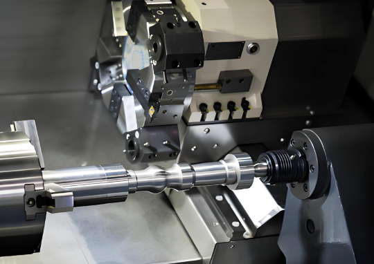
Precision Turning and Swiss-Style Machining
When your parts are cylindrical—shafts, pins, connectors, or threaded fasteners—turning operations take center stage. A lathe spins the workpiece while stationary cutting tools shape it along the X and Z axes. CNC turning centers control tool position with sub-micron precision, creating complex profiles impossible to achieve manually.
For small, intricate CNC machined components, Swiss-style machining represents the gold standard. Originally developed for watchmaking in the 1870s, Swiss lathes operate with a unique guide bushing system that supports the workpiece extremely close to the cutting tool. This design virtually eliminates deflection—the slight bending that occurs when cutting forces act on slender parts.
Swiss machines offer several precision advantages over conventional lathes:
- Reduced Deflection: Support at the cutting zone allows deeper cuts in single passes and maintains dimensional consistency on long, slender parts
- Multi-Spindle Operations: Primary and secondary spindles enable complete part machining—including features on the back side—without manual intervention
- Higher RPMs Without Vibration: Faster machining speeds with improved surface finishes
- Simultaneous Operations: Multiple tool paths perform turning, drilling, and milling concurrently, reducing cycle times dramatically
Swiss machining excels for bar stock between 2mm-38mm diameter, making it ideal for medical screws, electronic connectors, and aerospace fasteners where micron-level precision is mandatory.
Why Subtractive Beats Additive for Precision
You might wonder: with all the buzz around 3D printing, why does subtractive manufacturing dominate precision applications? The answer comes down to achievable accuracy and surface quality.
According to manufacturing comparisons, CNC machining components consistently outperform additive alternatives in three critical areas:
- Dimensional Accuracy: Subtractive machines achieve tighter tolerances than additive processes—often by an order of magnitude. Additive parts requiring high-accuracy features frequently need secondary machining after printing.
- Surface Finish: CNC processes deliver smoother, more precise surface finishes directly from the machine, reducing or eliminating post-processing requirements.
- Production Volume Efficiency: CNC machines achieve higher production rates with automated material loading and part removal—essential for consistent quality across large runs.
This doesn't mean additive manufacturing has no place in precision applications—it excels for complex internal geometries and rapid prototyping. But when your cnc machining components demand the tightest tolerances and best surface finishes, subtractive processes remain the proven choice.
With these core processes understood, the next critical factor becomes material selection—because even the most capable machining process cannot overcome limitations imposed by the wrong material choice.
Material Selection for Precision Machined Components
Here's a truth many machined components manufacturers won't volunteer: the material you choose can make or break your precision requirements before cutting even begins. You might specify ±0.0005-inch tolerances, but if your material selection doesn't support those specifications, you're setting your project up for disappointment—and unexpected costs.
Material properties directly influence every aspect of precision machining: achievable tolerances, surface finish quality, tool wear rates, and ultimately, part performance. Understanding these relationships gives you a significant advantage when working with suppliers and helps you avoid costly specification mismatches.
Matching Materials to Precision Requirements
Different materials respond to machining forces in fundamentally different ways. Some cut cleanly with minimal tool wear. Others generate excessive heat, cause rapid tool degradation, or produce poor surface finishes regardless of how carefully the machining parameters are set.
Consider machinability—a measure of how easily a material can be cut, drilled, and shaped. According to industry data, machinability is often represented by a relative index based on free-machining steel equaling 100. Aluminum 6061 scores approximately 270, making it nearly three times easier to machine than the baseline steel. Titanium? It scores around 20—requiring five times more effort than steel to achieve comparable results.
Why does this matter for your precision machined components? Higher machinability typically translates to:
- Tighter achievable tolerances: Materials that cut cleanly produce more consistent dimensions with less variation
- Better surface finishes: Reduced cutting forces mean smoother surfaces directly from the machine
- Lower costs: Faster cycle times and reduced tool wear decrease per-part expenses
- More consistent quality: Predictable material behavior leads to repeatable results across production runs
Let's examine the most common materials for precision machined metal parts and when each makes sense for your application.
Aluminum Alloys: The Precision Workhorse
When engineers need lightweight precision without breaking the budget, aluminum alloys often emerge as the optimal choice. Aluminum 6061 comes out as the best overall performer for general-use parts where moderate strength and low cost matter most.
Aluminum's excellent thermal conductivity helps dissipate heat during machining, reducing thermal distortion that can compromise dimensional accuracy. Its relatively soft nature allows faster cutting speeds and longer tool life—factors that directly impact both cost and achievable precision.
However, aluminum isn't universally appropriate. Its lower strength compared to steel limits applications where high mechanical loads exist, and its softness can make achieving certain surface textures challenging.
Stainless Steels: When Durability Meets Precision
For applications requiring corrosion resistance, strength, and precision, stainless steel justifies its higher machining cost. Medical instruments, food processing equipment, and marine components frequently specify stainless grades precisely because the material performs reliably in demanding environments.
The trade-off? Stainless steels work-harden during machining—meaning the material becomes harder as cutting progresses. This behavior requires careful control of feeds, speeds, and cutting depths to prevent the surface layer from becoming too hard for subsequent passes. Experienced machined components manufacturers understand these nuances and adjust their processes accordingly.
Titanium: Aerospace-Grade Precision
When weight savings and strength are both critical—think aerospace structural components or medical implants—titanium becomes the material of choice despite its challenging machinability. Its strength-to-weight ratio exceeds steel's while offering excellent biocompatibility for medical applications.
But titanium demands respect. According to machining cost analyses, titanium is only cost-effective in industries where performance demands override all else. Its low thermal conductivity concentrates heat at the cutting edge, accelerating tool wear. Its tendency to gall—essentially welding itself to cutting tools under pressure—requires specialized tooling and conservative machining parameters.
Engineering Plastics: Precision Beyond Metals
Not every precision-machined component requires metal. Engineering plastics like PEEK, Delrin, and Ultem offer unique combinations of properties: electrical insulation, chemical resistance, or FDA compliance that metals cannot provide.
Plastics present their own precision challenges. Thermal expansion coefficients significantly higher than metals mean temperature-controlled environments become critical for tight-tolerance work. Material stress relief after machining can cause dimensional changes over time—a factor that must be considered for high precision machined components.
Superalloys and Exotic Metals in Demanding Applications
Some applications operate in environments so extreme that conventional materials simply cannot survive. Gas turbine engines, nuclear reactors, and chemical processing equipment demand materials that maintain their properties at temperatures where aluminum would melt and steel would lose most of its strength.
Enter superalloys—a class of metals with exceptional high-temperature strength. As precision machining specialists note, superalloys retain their strength at high temperatures, making them the preferred choice for hot environments like those downstream of combustors in gas turbine engines. Common grades include Inconel 718 and 625, Hastelloy X, and Haynes 282.
However, the same properties that make superalloys perform in extreme conditions complicate their machining:
- High yield strength requires greater cutting forces, demanding rigid machine tools and robust setups
- Poor thermal conductivity concentrates heat at the cutting edge, dramatically accelerating tool wear
- Work hardening makes each successive pass more difficult than the last
- Abrasive carbide phases in the microstructure act like embedded cutting tools working against your tooling
Machining superalloys successfully requires specialized tooling, conservative cutting parameters, and often, copious coolant flow. The consequences of improper technique include rapid tool failure, dimensional inaccuracy from thermal distortion, and work-hardened surfaces that resist subsequent operations.
Material Selection Comparison
The following table summarizes key considerations for common precision machining materials:
| Material Type | Typical Applications | Machinability Rating | Precision Considerations |
|---|---|---|---|
| Aluminum 6061 | Aerospace structures, electronics housings, general precision parts | High (~270) | Excellent dimensional stability; may require deburring; cost-effective for tight tolerances |
| Stainless Steel 304/316 | Medical devices, food equipment, marine components | Moderate (~45-50) | Work hardening requires careful parameter control; higher tool wear than aluminum |
| Brass | Decorative components, electrical connectors, valves | High (~300) | Excellent surface finish; ideal for functional and aesthetic precision-machined component applications |
| Copper | Electrical conductors, heat sinks, RF components | Moderate (~70) | Soft nature can cause burring; best reserved for electrical applications requiring conductivity |
| Titanium Grade 5 | Aerospace fasteners, medical implants, high-performance parts | Low (~20) | Requires rigid setups, specialized tooling; heat management critical for dimensional accuracy |
| Inconel 718 | Turbine components, nuclear reactors, chemical processing | Very Low (~12) | Extreme tool wear; thermal distortion concerns; near-net-shape blanks reduce machining requirements |
| Engineering Plastics (PEEK, Delrin) | Medical devices, electrical insulators, FDA-compliant components | High | High thermal expansion requires temperature control; stress relief may cause dimensional changes |
Practical Guidance for Material Selection
When evaluating materials for your precision machined components, consider these decision factors:
- For general precision at lowest cost: Aluminum 6061 offers the best balance of machinability, dimensional stability, and affordability
- For corrosion resistance with precision: Stainless steel grades justify higher machining costs when durability or hygiene requirements exist
- For small-batch or prototype work: Aluminum and brass reduce risk and cost due to shorter machine times and easier setups
- For extreme environments: Titanium and superalloys make sense only when performance demands override cost considerations
- For electrical or chemical applications: Copper or engineering plastics may be the only viable options despite their machining challenges
As material selection experts emphasize, understanding your project's specific requirements—function, size, complexity, and environmental conditions—guides you toward the appropriate material. The cheapest raw material rarely produces the lowest total cost when machining difficulty, tool wear, and scrap rates are factored in.
Material selection establishes the foundation for precision manufacturing success. But even the perfect material choice must align with the tolerance standards and regulatory requirements specific to your industry—a topic that varies dramatically between aerospace, medical, automotive, and electronics applications.
Industry-Specific Precision Requirements and Standards
Here's something that catches many engineers off guard: a tolerance specification that's perfectly acceptable for automotive components might be considered dangerously loose for aerospace applications—and completely inadequate for medical implants. The precision requirements for CNC precision parts vary so dramatically between industries that understanding these differences becomes essential before you ever request a quote.
Why does this matter? Because specifying tolerances without understanding industry context leads to two equally problematic outcomes. You might over-specify—demanding aerospace-grade precision for consumer electronics and paying three times more than necessary. Or you might under-specify—requesting standard tolerances for safety-critical components that regulatory bodies will reject during certification. Either scenario wastes time, money, and erodes trust with your manufacturing partners.
Aerospace and Defense Tolerance Standards
When components operate at 40,000 feet with lives depending on their performance, precision isn't optional—it's mandated. Aerospace precision machined products face the most stringent tolerance requirements of any industry, and for good reason. A turbine blade that's 0.002mm out of specification can cause catastrophic engine failure. A structural fastener with dimensional drift compromises the entire aircraft's integrity.
The aerospace industry operates under AS9100 certification requirements—a quality management system specifically designed for aviation, space, and defense organizations. This certification isn't just a plaque on the wall; it represents a commitment to excellence that extends through every aspect of precision component manufacturing.
Key precision specifications for aerospace applications include:
- Standard tight tolerances: ±0.01mm for general aerospace components
- High-precision requirements: ±0.005mm for flight-critical parts
- Aerospace/medical grade: ±0.002–0.003mm for turbine components and structural elements
- Ultra-precision applications: ±0.001mm for specialized instrumentation and guidance systems
Beyond dimensional accuracy, aerospace precision cnc parts must meet rigorous material traceability requirements. Every piece of raw stock must be traceable to its original mill certification. Heat treat records, surface treatment documentation, and inspection reports become permanent parts of the component's history—sometimes retained for decades.
Medical Device Precision Requirements
If aerospace tolerances seem demanding, medical device manufacturing adds another layer of complexity: the parts interact with human tissue. A surgical instrument that's dimensionally perfect but contaminated during manufacturing becomes a liability. A spinal implant that meets every tolerance but fails material biocompatibility testing cannot be used.
Medical precision mechanical components operate under ISO 13485 certification—the quality management standard specifically designed for medical device manufacturing. This framework ensures that every aspect of production, from incoming material inspection to final packaging, supports patient safety.
What makes medical device precision parts processing unique?
- Individual part verification: Unlike automotive applications where statistical sampling suffices, many medical implants require 100% dimensional inspection—every single part measured and documented
- Surface finish criticality: Ra values often specified at 0.4μm or better to minimize bacterial adhesion and tissue irritation
- Biocompatibility requirements: Material certifications must demonstrate compatibility with human tissue and body fluids
- Cleaning validation: Documented evidence that manufacturing residues have been removed to specified levels
- Tolerance ranges: Commonly ±0.01mm for surgical instruments, with implants often requiring ±0.005mm or tighter
A practical example illustrates the stakes: According to precision machining specialists, a PEEK housing for a medical sensor required ±0.01mm tolerance to fit micro-electronics properly. That single specification—seemingly straightforward—required temperature-controlled machining, specialized tooling, and individual part inspection to ensure consistent quality.
Automotive Precision: Volume Meets Consistency
Automotive cnc precision parts present a fundamentally different challenge than aerospace or medical components. The tolerances may be somewhat more relaxed—typically ±0.02–0.05mm for many applications—but the volume requirements and consistency expectations create their own demanding environment.
Consider this: an automotive supplier might produce 50,000 identical components per month. Every single part must fall within specification, because a single out-of-tolerance component can shut down an assembly line. The cost of a line stoppage at a major automotive manufacturer can exceed $10,000 per minute.
Automotive precision parts processing operates under IATF 16949 certification—a quality management system that emphasizes:
- Statistical Process Control (SPC): Real-time monitoring of critical dimensions to detect drift before parts go out of specification
- Process capability requirements: Cpk values of 1.33 or higher, demonstrating that the process consistently produces parts well within tolerance limits
- Production Part Approval Process (PPAP): Comprehensive documentation proving that the manufacturing process can reliably produce conforming parts at volume
- Mistake-proofing (Poka-yoke): Physical and procedural safeguards that prevent defective parts from reaching customers
The precision requirements vary by component function. Powertrain components—transmission gears, valve bodies, fuel injector parts—demand tighter tolerances than body panels or interior trim. Safety-critical items like brake components receive the same scrutiny as aerospace parts.
Electronics and Semiconductor Precision Standards
The electronics industry pushes precision machined products into territory where traditional measurement methods struggle to verify results. Semiconductor manufacturing equipment components, RF waveguides, and precision connectors routinely specify tolerances that would be exceptional in any other industry.
Electronics precision mechanical components face unique challenges:
- Micro-manufacturing tolerances: CNC micro machining achieves ±0.002–0.005mm, with specialized processes like micro EDM reaching ±0.001mm
- Thermal stability requirements: Components must maintain dimensional accuracy across operating temperature ranges
- Electrical conductivity specifications: Material selection and surface finish directly impact electrical performance
- Cleanliness standards: Particulate contamination measured in parts per million for semiconductor applications
The precision requirements scale with technology advancement. As electronic devices shrink, the components that manufacture and test them must achieve correspondingly tighter tolerances. What was considered ultra-precision a decade ago is now standard for many electronics applications.
Matching Your Requirements to Industry Standards
Understanding where your application falls on this spectrum helps you specify appropriate tolerances—tight enough to ensure proper function, but not so aggressive that costs spiral unnecessarily.
According to tolerance machining experts, the relationship between tolerance and cost follows an exponential curve: tightening tolerances from ±0.05mm to ±0.01mm may increase cost by 30–200%. The machining time rises by 30–200%, inspection effort doubles, tool life drops by over 50%, and scrap rate increases significantly.
The key insight? Tight tolerances should only be applied to surfaces affecting fit, sealing, safety, or motion accuracy. A customer specifying ±0.02mm across an entire aluminum bracket—when only three holes were critical—found that relaxing other features to ±0.1mm improved productivity nearly threefold.
This industry context becomes essential when designing parts and selecting manufacturing partners. A supplier certified to AS9100 demonstrates the capability and quality systems necessary for aerospace work. ISO 13485 certification signals competence in medical device manufacturing. IATF 16949 indicates automotive production expertise.
With industry requirements understood, the next critical factor becomes designing your parts to achieve required tolerances cost-effectively—because even the right material and the right supplier cannot overcome fundamental design decisions that make tight tolerances unnecessarily difficult to achieve.
Design Guidelines for Achieving Tight Tolerances Cost-Effectively
Here's a frustrating reality many engineers discover too late: that beautifully detailed CAD model you spent weeks perfecting might be nearly impossible to manufacture at the tolerances you specified—or if it is manufacturable, it costs three times your budget. The gap between what's designable and what's manufacturable catches even experienced professionals off guard.
Design for Manufacturability (DFM) bridges this gap for precision cnc machining parts. By understanding how specific design decisions impact achievable tolerances and costs, you can make smarter specifications from the start—avoiding the painful cycle of quotes, redesigns, and compromises that plagues poorly optimized designs.
Tolerance Specifications That Balance Performance and Cost
Let's start with the uncomfortable truth about tolerances: the relationship between precision and cost isn't linear—it's exponential. According to manufacturing cost analyses, moving from rough machining tolerances (0.76mm/0.030 inches) to precision tolerances (0.025mm/0.001 inch) increases costs by approximately 4x. Ultra-precision tolerances (0.0025mm/0.0001 inch) can cost 24 times more than standard machining.
Why does this cost curve steepen so dramatically? Tighter tolerances fundamentally change how machining parts must be manufactured, inspected, and validated:
- Temperature-controlled environments: Precision work often requires climate control to prevent thermal expansion from affecting dimensions
- Iterative machining processes: Cut, measure, adjust, repeat—lead times extend as the process becomes cyclical
- Specialized inspection protocols: Standard sampling gives way to comprehensive measurement routines
- Increased scrap rates: More parts fall outside tighter specification windows
- Higher tooling costs: Precision cutting tools with tighter tolerances command premium prices
The practical takeaway? Tight tolerances should only appear on dimensions that genuinely require them. A precision machined part with ±0.001-inch tolerances specified on every feature will cost dramatically more than one where only critical interfaces receive tight control while non-functional surfaces accept standard tolerances.
Understanding Tolerance Stacking
Tolerance stacking—also called tolerance stack-up—determines how individual part tolerances combine to affect overall assembly accuracy. According to precision machining experts, this analysis is crucial for ensuring tools maintain their functional requirements while remaining cost-effective to produce.
Consider a slot machined with three features: a left corner radius (0.125" ±0.001"), a flat section (0.250" ±0.002"), and a right corner radius (0.125" ±0.001"). Using worst-case analysis—where every tolerance goes to its extreme—the total slot width could vary from 0.496" to 0.504", giving a worst-case tolerance of ±0.004".
Two primary methods exist for analyzing tolerance stacks:
- Worst-Case Analysis: Assumes all tolerances simultaneously reach their maximum or minimum limits. This conservative approach guarantees all assemblies function but often requires tighter individual tolerances than statistically necessary.
- Statistical Analysis: Calculates the probability that tolerances will combine to create problems, based on normal distribution. For assemblies with four or more toleranced features, this method typically allows looser individual tolerances while still achieving acceptable assembly performance.
The insight here? Poor tolerance allocation across an assembly—rather than individual tight tolerances—often causes manufacturing failures. Smart datum structure and intelligent tolerance distribution can achieve the same functional requirements with significantly looser individual part tolerances on your cnc precision machined components.
Geometric Features That Challenge Precision
Certain design features inherently complicate precision parts machining. Understanding these challenges before finalizing your design prevents costly surprises during quoting—or worse, during production.
Hole Depth-to-Diameter Ratios
A good rule of thumb: ensure hole depth doesn't exceed 6x the diameter. According to DFM specialists, this best practice ensures tooling can reach the hole at standard speeds. Deeper holes require slower machining to avoid tool breakage, significantly affecting both cost and lead times.
For complex machined parts with deep hole requirements, consider these alternatives:
- Machine from both sides when possible, meeting in the middle
- Use larger diameter holes where functional requirements permit
- Specify through-holes instead of blind holes when design allows
Internal Corner Radii
Square corners on interior pockets are difficult—sometimes impossible—to machine due to tooling constraints. Rotating cutting tools naturally create radiused corners; achieving sharp internal corners requires secondary operations like EDM that dramatically increase costs.
The solution? Add radii to internal corners. But remember: the smaller the radius, the smaller the tooling required. According to machining experts, designing radii to accommodate standard tooling sizes of 0.10", 0.015", and 0.03" optimizes machining time and reduces tool breakage risk.
Wall Thickness Considerations
Thin walls present significant precision challenges. When running thin-walled precision cnc machining parts, machinists must slow down RPMs and feed rates to prevent material shattering or deflection. This slowdown drives up both cost and lead time.
Minimum practical wall thicknesses vary by material:
- Aluminum: 0.5mm (0.020") minimum for stability during machining
- Steel: 0.8mm (0.030") to resist cutting forces
- Plastics: 1.0mm (0.040") or more due to flexibility and thermal sensitivity
If thin walls are functionally necessary, expect increased costs and discuss support strategies with your manufacturer—specialized workholding or staged machining operations may be required.
Cavity and Pocket Depth
Similar to hole depth constraints, pocket depth affects tool reach and rigidity. Deep, narrow pockets require long, slender tools that deflect under cutting forces—compromising dimensional accuracy and surface finish. Design pockets with depth-to-width ratios of 4:1 or less when possible.
Prioritized DFM Guidelines for Precision Parts
Based on their impact on both manufacturability and cost, consider these guidelines in order of importance when designing precision parts machining projects:
- Apply tight tolerances selectively: Specify precision only where function demands it. Identify critical interfaces, sealing surfaces, and motion-control features—then relax tolerances elsewhere. A customer who specified ±0.02mm across an entire bracket improved productivity nearly threefold by relaxing non-critical features to ±0.1mm.
- Choose materials for machinability: Not all materials achieve the same tolerances with equal effort. When 303 stainless steel and 304 stainless can both meet functional requirements, choose 303—it machines much more easily, reducing cost and improving consistency.
- Design for minimum setups: Each time a part is repositioned in a machine, alignment error accumulates. Design the simplest geometry that meets functional needs, allowing complete machining in fewer setups. Fewer setups mean better tolerance control between features and more consistent results.
- Respect depth-to-diameter ratios: Keep hole depths below 6x diameter and pocket depths below 4x width. Violations require slower machining, specialized tooling, or secondary operations—all of which increase cost.
- Add generous internal radii: Design internal corners with radii that match standard tool sizes (0.10", 0.015", 0.03"). Smaller radii require smaller tools that break more easily and cut more slowly.
- Maintain adequate wall thickness: Design walls thick enough to resist machining forces without deflection. When thin walls are unavoidable, discuss support strategies with your manufacturer early.
- Provide complete documentation: Include material specifications with acceptable alternatives, required certifications, critical-to-quality dimensions clearly marked, and surface finish requirements. More information upfront prevents costly miscommunications.
The Hidden Cost of Over-Specification
Perhaps the most expensive tolerance is the one that provides no functional benefit. According to manufacturing analysis, precision feels like progress—there's an inherent sense that tighter equals better. But that 0.025mm tolerance you just specified might have doubled your part cost and tripled your lead time.
The manufacturing reality is sobering: standard machining processes efficiently achieve ±0.1mm (±0.004 inch) tolerances. Tightening to ±0.025mm (±0.001 inch) enters precision manufacturing territory, requiring temperature-controlled environments, thermal stabilization, and specialized inspection routines.
Before specifying tight tolerances on your next cnc precision machined components project, ask yourself: What does this dimension actually control? How does variation affect part performance? Often this analysis reveals opportunities for tolerance relaxation without functional compromise—and significant cost savings.
With design guidelines established, the next critical factor becomes verification: how do manufacturers confirm that your complex machined parts actually meet the tolerances you specified? The answer involves sophisticated inspection technologies that most suppliers never fully explain.
Quality Control and Inspection Methods for Precision Parts
How do you know your precision machining parts actually meet the tolerances specified on your drawings? This question rarely gets satisfying answers during the quoting process—yet verification methods ultimately determine whether you receive conforming parts or expensive scrap. Understanding inspection technologies helps you ask better questions and evaluate supplier quality systems more effectively.
Modern quality control for cnc components extends far beyond simple caliper measurements. Sophisticated inspection technologies capture dimensional data at micron-level resolution, while statistical methods ensure consistency across production runs. Let's explore the verification processes that separate capable precision machined parts manufacturers from those making promises they can't verify.
CMM Inspection and Dimensional Verification
Coordinate Measuring Machines represent the gold standard for dimensional verification of high precision machining components. These sophisticated systems capture data points from an object's surface using a touch probe that moves along three cartesian axes (X, Y, and Z), according to CMM inspection specialists. This process generates a detailed spatial map—often called a "point cloud"—that's analyzed to confirm parts meet design specifications.
Why does CMM inspection matter for your precision cnc machined components? Consider the alternative: manual measurement with handheld tools introduces operator variability, limits the features that can be verified, and provides no digital record for traceability. CMMs eliminate these limitations through computer-controlled measurement paths that capture hundreds or thousands of data points with sub-micron repeatability.
Different CMM configurations address different inspection challenges:
- Bridge CMMs: The workhorse of dimensional inspection, offering balanced accuracy, speed, and versatility for parts ranging from small precision components to larger manufactured items
- Gantry CMMs: Designed for the largest and most challenging parts, these systems handle aerospace and shipbuilding components where large-scale precision is non-negotiable
- Articulated Arm CMMs: Portable systems that bring precision measurement directly to the shop floor, ideal for accessing complex geometries or measuring parts too large to move
- Horizontal Arm CMMs: Optimized for large, voluminous objects like automotive body components where accessibility matters as much as accuracy
Beyond basic dimensional verification, modern CMMs offer advanced capabilities that push measurement boundaries. High-speed scanning captures thousands of data points rapidly, providing detailed surface maps for complex geometries. CAD integration allows direct comparison between measured data and digital design models, facilitating real-time quality control decisions.
Beyond CMM: Complementary Inspection Technologies
While CMM inspection anchors most quality programs, certain applications demand specialized measurement approaches. Optical measurement systems use non-contact methods to verify dimensions—particularly valuable for delicate machining component surfaces that contact probes might damage, or for soft materials that would deform under probe pressure.
Surface profilometry addresses a dimension that CMMs don't typically capture: surface texture. When your specifications include Ra (average roughness) requirements, profilometers trace across machined surfaces to quantify the microscopic peaks and valleys that determine functional performance. Medical implants requiring specific surface textures for tissue integration, or sealing surfaces demanding particular roughness values, rely on profilometry for verification.
For internal features that probes cannot reach, techniques like industrial CT scanning provide visibility into hidden geometries. While expensive and slower than traditional methods, CT inspection reveals internal defects, verifies wall thicknesses, and confirms complex internal passages in ways no other technology can match.
Inspection Methods Comparison
Selecting appropriate inspection methods depends on what you're measuring, required accuracy, and production context. This comparison helps match verification approaches to application requirements:
| Method | Measurement Type | Typical Accuracy | Best Applications |
|---|---|---|---|
| Bridge CMM | Dimensional geometry, GD&T features | ±0.001–0.003mm | General precision parts, first article inspection, production sampling |
| Gantry CMM | Large-scale dimensional verification | ±0.005–0.010mm | Aerospace structures, large castings, automotive body components |
| Articulated Arm CMM | Portable dimensional measurement | ±0.025–0.050mm | Shop floor verification, large assemblies, in-process checks |
| Optical/Vision Systems | 2D profiles, edge detection, small features | ±0.002–0.005mm | Delicate surfaces, high-speed measurement, 2D profile verification |
| Surface Profilometry | Surface roughness (Ra, Rz) | 0.001μm resolution | Sealing surfaces, medical implants, friction-critical interfaces |
| Industrial CT Scanning | Internal geometry, hidden features | ±0.010–0.050mm | Complex internal passages, assembly verification, defect detection |
Statistical Process Control in Precision Manufacturing
Inspection catches defects—but wouldn't you rather prevent them? Statistical Process Control (SPC) shifts quality assurance from reactive detection to proactive prevention, using real-time data analysis to identify process drift before parts go out of specification.
According to manufacturing process experts, a statistically capable process is one where the chance of producing a part characteristic out of tolerance is quite remote. The process capability index (Cp) measures how many standard deviations fit within a tolerance—the higher the Cp, the more capable and consistent the process.
What do these capability levels mean in practice?
- Cp 1.0: Process spread equals tolerance width—roughly 0.27% defect rate (2,700 ppm)
- Cp 1.33: Industry standard target—approximately 1 in 16,000 chance of out-of-tolerance parts
- Cp 1.67: Enhanced capability—fewer than 1 in 100,000 parts expected out of specification
- Cp 2.0: Six sigma performance—near-zero defect probability
For precision machining parts, SPC becomes essential when production volumes make 100% inspection impractical. Customers typically machine parts with hundreds of characteristics demanding enhanced precision and Cp levels of 1.33 and 1.67, as process capability specialists note. At these capability levels, sampling inspection provides confidence that the entire production lot meets specification.
The practical implementation involves tracking critical dimensions on control charts—visual tools that plot measurement results against calculated control limits. When measurements trend toward limits without yet exceeding them, operators intervene with tool adjustments, offset corrections, or process parameter changes. This prevents defects rather than simply detecting them.
Quality Certifications That Ensure Consistent Precision
How do you verify a supplier's quality claims without auditing their facility yourself? Industry certifications provide third-party validation that quality systems meet recognized standards.
For automotive applications, IATF 16949 certification demonstrates comprehensive quality management aligned with the demanding requirements of global automakers. This certification requires documented SPC implementation, production part approval processes, and systematic defect prevention—not just detection. Suppliers certified to this standard have proven their ability to deliver consistent precision cnc machined components at automotive volumes.
As noted by quality assurance professionals, certifications such as ISO are not just badges of honor; they represent a provider's commitment to maintaining the highest standards of quality and efficiency. ISO 9001 establishes baseline quality management requirements, while industry-specific certifications like AS9100 (aerospace) and ISO 13485 (medical devices) add sector-specific controls.
When evaluating precision machined parts manufacturers, certifications signal capability—but the real question is whether their quality systems match your specific requirements. A supplier with automotive certification may lack the individual part traceability required for aerospace work. Medical device manufacturers need FDA registration and biocompatibility expertise that general machining shops typically don't possess.
Understanding these verification methods transforms how you evaluate suppliers and interpret inspection reports. But quality systems only matter if the underlying manufacturing economics work. The next critical factor—cost drivers that most suppliers prefer not to discuss openly—determines whether your precision requirements remain affordable at production volumes.
Cost Factors and Pricing Considerations in Precision Machining
Ever wonder why two quotes for the same custom machined parts vary by 300%? The answer lies in cost drivers that most machining parts manufacturers prefer not to explain. Understanding these factors gives you negotiating leverage and helps you make smarter specification decisions—potentially saving thousands without sacrificing quality.
Pricing for cnc precision machining parts isn't arbitrary, though it often feels that way. Every specification you make—from tolerance requirements to surface finish—ripples through the manufacturing process, affecting machine time, tooling consumption, inspection effort, and scrap rates. Let's break down what actually drives costs so you can optimize your specifications intelligently.
Understanding the True Cost of Tight Tolerances
Here's the uncomfortable truth: the relationship between tolerance and cost isn't linear—it's exponential. According to precision manufacturing economists, moving from ±0.05mm tolerance to ±0.02mm may raise costs by around 50%. But going further from ±0.02mm to ±0.01mm can multiply costs several times due to hidden technical challenges.
Why does each additional micron cost more than the last? You cross a process-capability threshold where standard machining approaches no longer suffice:
- Slower machining speeds: Tighter tolerances require reduced feed rates and lighter cuts, extending cycle times dramatically
- More frequent tool changes: Precision work demands sharper tools—worn cutting edges that would be acceptable for standard work cause dimensional drift in precision parts production
- Temperature-controlled environments: Thermal expansion affects dimensions at the micron level, requiring climate-controlled facilities
- Extended inspection time: Every machined part requiring tight tolerances needs more comprehensive measurement routines
- Higher scrap rates: Narrower specification windows mean more parts fall outside acceptable limits
The most expensive tolerance is often the one that doesn't add functional benefit. Many design drawings include "safety tolerances"—very tight values included out of caution rather than based on function. A European automotive supplier discovered that relaxing non-critical tolerances from ±0.01mm to ±0.03mm reduced machining cost by approximately 22% while maintaining full functionality.
Cost Drivers Ranked by Impact
Not all cost factors carry equal weight. Based on typical manufacturing scenarios, here's how the major drivers stack up:
- Tolerance requirements: The single largest cost multiplier—tightening from standard to precision tolerances can increase costs 2-4x
- Material selection: Difficult-to-machine materials like titanium or Inconel require specialized tooling, slower speeds, and generate more scrap than aluminum or brass
- Part complexity: Multi-axis machining, deep cavities, thin walls, and intricate features demand longer programming time, custom tooling, and additional setups
- Surface finish specifications: Mirror finishes or specific Ra values often require secondary grinding, polishing, or specialized cutting strategies
- Production volume: Setup costs amortize across larger runs—prototype quantities carry significantly higher per-part costs
- Quality documentation: First Article Inspections, material certifications, and compliance documentation add overhead that scales with regulatory requirements
Volume Considerations from Prototyping to Production
Economies of scale dramatically affect precision milled parts pricing—but the relationship isn't always intuitive. Small batch or prototype runs carry higher per-unit costs due to setup time and minimal material usage, according to manufacturing cost analysts.
What changes as volumes increase?
- Tooling and setup costs amortize: A $2,000 setup cost adds $200 per part for 10 pieces but only $2 per part for 1,000 pieces
- Automated processes become viable: Bar feeding, palletizing, and lights-out machining reduce labor costs at volume
- Material purchasing improves: Bulk material orders command better pricing than small-lot purchases
- Process optimization pays off: Time invested in cycle time reduction yields returns multiplied across larger runs
However, volume isn't always the answer. For custom machined parts with high complexity, the learning curve on each new batch means prototype pricing often reflects real manufacturing challenges rather than just setup amortization.
Secondary Operations: Hidden Cost Multipliers
The machining quote you receive rarely represents total part cost. Secondary operations—heat treatment, surface finishing, plating, and assembly—add costs that catch many buyers off guard.
Heat treatment affects both precision and cost in complex ways. Hardening processes improve wear resistance but often cause dimensional changes requiring post-heat-treat machining. This means machining the part twice—once before treatment, once after—effectively doubling machine time for critical features.
Surface finishing operations similarly impact budgets:
- Anodizing: Adds 0.0005-0.003 inches to dimensions, requiring tolerance adjustments in the machining phase
- Plating: Electroless nickel, chrome, and other platings add dimensional buildup that must be accounted for
- Grinding: When machined surfaces can't achieve required finishes or tolerances, grinding adds significant cost
- Polishing: Manual polishing for cosmetic or functional requirements becomes labor-intensive and difficult to quote accurately
The key insight? Discuss secondary operations during the design phase, not after machining quotes arrive. Experienced machining parts manufacturers can often suggest specification adjustments that achieve the same functional result at lower total cost.
Understanding these cost drivers transforms your conversations with suppliers from price negotiation to value optimization. But even with perfect cost awareness, defects can derail projects—and most suppliers won't volunteer information about the precision machining failures they've experienced or how to prevent them.
Common Precision Machining Defects and Prevention Strategies
What happens when your precision mechanical parts arrive and something's wrong? Understanding common defects—and more importantly, how to prevent them—separates informed buyers from those who discover problems only after assembly fails. Most suppliers won't discuss their failure modes, but this knowledge protects your projects and helps you evaluate manufacturing partners more effectively.
According to industry research, 30% of CNC components require adjustments due to quality issues. That's nearly one in three parts needing rework—a statistic that underscores why understanding defect prevention matters as much as understanding machining processes themselves.
Preventing Dimensional Drift in Production Runs
Imagine your first 50 machined products measure perfectly within specification. Then parts 51 through 100 start trending toward the tolerance limit. By part 150, you're producing scrap. This is dimensional drift—a gradual deviation from target dimensions that accumulates throughout production runs.
What causes this frustrating phenomenon?
- Tool degradation: As cutting edges lose sharpness, tool geometry changes. These changes accumulate, causing size variations that worsen throughout production. A tool that cuts 0.0001 inches oversize initially may drift to 0.0005 inches oversize after several hundred parts.
- Machine calibration drift: Minor 0.001-inch deviations in machine positioning render precision machine components unusable. Thermal expansion from machine operation compounds this effect over extended production cycles.
- Programming errors: Incorrect tool compensation values in G-code create systematic dimensional problems that repeat across every part until corrected.
- Material inconsistencies: Variations in raw material hardness or composition cause cutting forces to change, affecting achieved dimensions even with identical machining parameters.
Effective prevention requires systematic approaches. Rigorous calibration protocols using NIST-traceable dimensional metrology standards verify machine accuracy at regular intervals. Advanced tool monitoring systems detect wear in real-time, automatically adjusting parameters when wear exceeds thresholds. Temperature-controlled environments minimize thermal expansion through climate control systems and coolant regulation.
For large component machining where dimensional stability becomes even more critical, thermal compensation algorithms integrated with real-time temperature monitoring sensors help counteract expansion effects, maintaining precision tolerances throughout extended machining cycles.
Surface Finish Defects and Their Root Causes
Surface finish problems affect more than aesthetics—they impact functional performance. Roughness exceeding specifications causes premature wear, reduced fatigue life, and poor sealing performance in machining precision components. Understanding root causes helps you specify appropriate prevention measures.
Common surface defects and their origins include:
- Excessive roughness: Feed rates exceeding optimal values create excessive chip loads, leaving rough textures. The solution involves systematic parameter testing to establish ideal speed-feed combinations.
- Tool marks: Visible lines or ridges from tool-workpiece interaction indicate improper tool geometry, incorrect speeds, or inadequate rigidity. High-speed machining with reduced feeds and climb milling techniques often resolves these issues.
- Burn marks: Discolored patches indicate overheating during cutting—usually from inadequate cooling, excessive speeds, or dull tooling. High-pressure coolant systems using 1000 PSI help tools last longer and produce better finishes.
- Material pickup: Insufficient lubrication leads to heat generation and tool-workpiece adhesion, causing material to transfer onto machined surfaces. Proper coolant application and lubricant selection prevents this adhesion.
- Chatter marks: Regular wavy patterns indicate vibration during cutting. Machine rigidity limitations, excessive tool overhang, or improper cutting parameters allow resonant vibrations to transfer to surfaces.
Statistical process control through regular Ra and Rz measurements helps identify surface finish degradation before it becomes a rejection issue. Catching trends early enables corrective action while parts remain within specification.
Burrs, Thermal Distortion, and Other Common Defects
Beyond dimensional accuracy and surface finish, several other defect types plague precision mechanical parts production:
- Burr formation: Small protrusions at edges occur especially in ductile materials like aluminum. Specialized toolpaths, chamfering operations, and sacrificial backing materials minimize formation. When burrs are unavoidable, post-machining deburring through mechanical, thermal, or electrochemical methods removes them.
- Thermal distortion: Heat generated during machining causes workpiece expansion and warping. High-temperature alloys with poor thermal conductivity—like titanium and Inconel—are particularly susceptible. According to thermal management specialists, tool wear increases by 50-60% when machining at high temperatures, compounding distortion problems.
- Work hardening: Some materials become progressively harder as machining continues, significantly increasing cutting forces and tool wear. Nickel-based superalloys and titanium alloys exhibit this strain-hardening effect, requiring low cutting depths with optimized feed rates.
- Chip recutting: When chips aren't properly evacuated, cutting tools re-engage with them, damaging surfaces and potentially breaking tools. Improved chip evacuation methods, optimized tool paths, and chip breakers mitigate this issue.
Environmental and Process Control Factors
Many defects trace back to environmental conditions and process control—factors that differentiate capable precision machine components manufacturers from those struggling with consistency.
Temperature stability matters more than many realize. A 10°F temperature swing in a machining facility can cause dimensional changes of several thousandths of an inch in large aluminum parts. Climate-controlled machining environments maintain temperature within ±2°F to prevent thermal-induced dimensional variation.
Predictive maintenance prevents unexpected failures that compromise quality. Real-time monitoring of spindle condition through vibration analysis detects bearing degradation before it affects dimensional accuracy. IoT-driven CNC monitoring systems track tool wear progression, enabling proactive replacement before parts drift out of specification.
Operator training represents an often-overlooked defense against defects. Comprehensive programs covering operation, troubleshooting, and quality control enable problem identification before production impact. Experienced operators detect potential issues—including subtle signs of tool wear and machine misalignment—that automated systems might miss.
Understanding these defect mechanisms and prevention strategies transforms how you evaluate suppliers. Ask specific questions about tool monitoring systems, calibration schedules, environmental controls, and SPC implementation. The answers reveal whether a supplier genuinely controls their process—or simply hopes for the best. With this defect-prevention knowledge in hand, the final critical factor becomes selecting a manufacturing partner whose capabilities align with your precision requirements.
Selecting the Right Precision Machining Partner
You've mastered tolerances, materials, quality systems, and cost factors. Now comes the decision that determines whether all that knowledge translates into successful parts: choosing the right machined parts manufacturer. This selection process separates projects that run smoothly from those plagued by delays, quality escapes, and frustrating communication breakdowns.
The challenge? Every supplier claims precision capabilities, quality certifications, and responsive service. Distinguishing genuine expertise from marketing requires a systematic evaluation approach—one that goes beyond certificates on walls to assess real operational competence.
Evaluating Supplier Capabilities and Certifications
Certifications provide a starting point, but they're not the finish line. According to manufacturing partner specialists, a certificate on the wall isn't enough—the real test is how deeply the quality mindset is embedded in their culture.
What certifications actually indicate varies by your application:
- ISO 9001: Baseline quality management—necessary but not sufficient for precision work
- IATF 16949: Automotive-specific quality systems including Statistical Process Control, Production Part Approval Process, and systematic defect prevention
- AS9100: Aerospace and defense quality management with rigorous traceability requirements
- ISO 13485: Medical device manufacturing with individual part verification and biocompatibility documentation
Beyond certifications, evaluate inspection capabilities directly. A capable precision machined parts manufacturer should demonstrate CMM equipment from reputable brands, documented calibration records, and the ability to hold tolerances of ±0.001 inches or better with surface finishes as fine as Ra 0.2μm.
Ask pointed questions that reveal operational reality. Request sample First Article Inspection reports for parts with similar complexity to yours. Inquire about their process for handling non-conforming parts. Their answers reveal more about actual capability than any marketing brochure.
Equipment and Technology Assessment
Modern cnc machined parts require modern equipment. Evaluate whether potential partners have invested in capabilities matching your requirements:
- Multi-axis machining: 5-axis CNC machines for complex geometries requiring multiple approach angles
- Swiss-style lathes: Essential for small-diameter precision cnc machined parts with tight tolerances
- Advanced metrology: CMMs, optical measurement systems, and surface profilometry for comprehensive verification
- Automation capability: Bar feeders, pallet systems, and lights-out machining for volume production consistency
According to supplier evaluation experts, visiting the facility to inspect equipment firsthand provides valuable insights into operational standards that quotes and certifications cannot convey.
From Rapid Prototyping to Scalable Production
Your needs today may differ dramatically from your needs six months from now. A supplier who excels at prototypes may struggle with production volumes—or vice versa. Evaluating scalability prevents painful transitions between manufacturing partners as your project matures.
Look for machined parts manufacturers demonstrating experience across the volume spectrum:
- Prototype capability (1-100 units): Fast turnaround, design iteration support, DFM feedback
- Low-volume production (100-1,000 units): Consistent quality, reasonable lead times, process documentation
- High-volume production (10,000+ units): Statistical process control, automated inspection, supply chain stability
Rapid prototyping capability with fast lead times accelerates product development significantly. When you can iterate designs in days rather than weeks, you compress development schedules and reach market faster. Some facilities, like Shaoyi Metal Technology, deliver precision CNC machining services with lead times as fast as one working day—enabling design validation cycles that traditional suppliers simply cannot match.
For automotive applications specifically, IATF 16949 certification combined with strict Statistical Process Control ensures the consistency required for high-volume production. Shaoyi's facility exemplifies this combination, scaling seamlessly from rapid prototyping to mass production while maintaining the high-tolerance specifications that automotive supply chains demand.
Communication and Project Management
Technical capability means nothing if communication breaks down. Poor communication is a significant red flag, according to partner evaluation specialists. In today's fast-paced environment, you need a partner who responds quickly, provides proactive updates, and is transparent when issues arise.
Evaluate communication practices during the quoting process—it's a preview of production behavior:
- How quickly do they respond to RFQs and technical questions?
- Do they offer proactive Design for Manufacturability feedback?
- Can they clearly explain their quality processes and capabilities?
- Do they have dedicated project managers for complex orders?
A great partner doesn't just blindly follow your prints—they collaborate to improve them. This proactive DFM engagement indicates expertise and investment in your success rather than simply processing orders.
Supplier Evaluation Checklist
Use this comprehensive checklist when evaluating potential custom cnc parts suppliers:
- Certifications verified: Confirm relevant quality certifications (ISO 9001, IATF 16949, AS9100, ISO 13485) are current and appropriate for your industry
- Inspection capabilities documented: CMM equipment, calibration records, and sample inspection reports reviewed
- Equipment matches requirements: Multi-axis capability, appropriate technology for your part complexity and material
- Tolerance capabilities proven: Evidence of consistently holding tolerances similar to your requirements
- Material expertise demonstrated: Experience with your specific materials, including certifications and traceability
- Volume scalability confirmed: Capability to support prototype through production volumes without quality degradation
- On-time delivery metrics shared: OTIF rates above 95% with willingness to provide supporting data
- Communication responsiveness tested: Response times during quoting indicate production communication patterns
- DFM feedback provided: Proactive suggestions for design optimization demonstrate engagement and expertise
- Supply chain stability verified: Material sourcing reliability and contingency planning documented
- References available: Customer references with similar applications willing to share their experience
Making the Final Decision
After systematic evaluation, the final selection often comes down to trust and cultural fit. According to manufacturing partnership experts, a true partner asks insightful questions, offers creative solutions, and invests in building a collaborative relationship.
Avoid the trap of selecting solely on price. The most successful decisions look beyond unit cost to consider Total Value of Ownership—factoring in risk costs, communication efficiency, quality consistency, and long-term partnership potential. A 20% lower quote that results in production delays, quality escapes, and rework costs more in the end than a higher-priced partner who delivers reliably.
Whether you're sourcing complex chassis assemblies, custom metal bushings, or precision cnc machined parts for any demanding application, the right manufacturing partner becomes a competitive advantage. By systematically evaluating capabilities, verifying quality systems, and assessing communication practices, you select a partner positioned to support not just today's project—but your long-term manufacturing success.
Frequently Asked Questions About CNC Precision Machining Parts
1. What is CNC machining parts and how does the process work?
CNC machining parts involves computer-controlled subtractive manufacturing where material is systematically removed from solid workpieces using pre-programmed instructions. The process begins with a CAD model that defines exact geometries, which CAM software translates into G-code controlling every cutting tool movement. Unlike conventional machining relying on operator skill, CNC precision machining eliminates human error and achieves repeatability of ±0.0005 inches or tighter. This technology enables micron-level accuracy through real-time feedback systems that monitor and correct for machine deflection, tool wear, and thermal expansion during production.
2. What tolerances can precision CNC machining achieve?
Precision CNC machining typically achieves tolerances of ±0.0005 inches, with specialized setups reaching ±0.0001 inches (1-5 microns). Standard CNC machining delivers ±0.005 inches, while precision work represents a tenfold improvement in dimensional control. Industry leaders routinely hold 1-3 micron tolerances for medical device components. However, achieving tighter tolerances follows an exponential cost curve—moving from ±0.05mm to ±0.01mm can multiply costs several times due to slower machining speeds, temperature-controlled environments, specialized inspection, and higher scrap rates.
3. What materials are best for CNC precision machined parts?
Material selection directly impacts achievable tolerances and costs. Aluminum 6061 offers the best balance with a machinability rating of 270, excellent thermal conductivity, and cost-effectiveness. Stainless steels provide corrosion resistance but work-harden during machining. Titanium delivers superior strength-to-weight ratio for aerospace and medical applications but scores only 20 on machinability, requiring specialized tooling. Brass (rating 300) produces excellent surface finishes, while engineering plastics like PEEK suit electrical insulation needs. Superalloys like Inconel maintain strength at extreme temperatures but demand conservative cutting parameters.
4. How do I choose the right precision machining partner?
Evaluate suppliers systematically by verifying relevant certifications (ISO 9001, IATF 16949 for automotive, AS9100 for aerospace, ISO 13485 for medical). Request sample First Article Inspection reports and assess CMM equipment capabilities. Confirm multi-axis machining technology matches your part complexity. Test communication responsiveness during quoting—it previews production behavior. Look for partners offering DFM feedback and scalability from prototyping to production. Facilities like Shaoyi Metal Technology combine IATF 16949 certification with Statistical Process Control and lead times as fast as one working day for automotive precision components.
5. What are common defects in precision machined parts and how are they prevented?
Common defects include dimensional drift from tool degradation and thermal expansion, surface finish issues from incorrect parameters, burr formation at edges, and thermal distortion in poor-conductivity materials. Prevention requires rigorous machine calibration using NIST-traceable standards, advanced tool monitoring with automatic parameter adjustment, temperature-controlled environments maintaining ±2°F stability, and Statistical Process Control tracking critical dimensions. High-pressure coolant systems (1000 PSI) improve tool life and surface quality. Predictive maintenance through vibration analysis detects spindle degradation before it affects dimensional accuracy.