 Small batches, high standards. Our rapid prototyping service makes validation faster and easier —

CNC Machining Prototype Service: From CAD File To Finished Part Fast
What CNC Machining Prototype Services Actually Deliver
Ever wondered how engineers test whether a new product design will actually work before investing thousands in production tooling? The answer lies in CNC machining prototype services—a process that transforms your digital CAD files into physical, functional parts you can hold, test, and validate.
A CNC machining prototype service uses computer-controlled machines to create sample parts from production-grade materials. Unlike 3D printing or handmade mockups, these machined parts match the strength, durability, and performance characteristics of your final product. This means you're testing real-world functionality, not just visual appearance.
The core value proposition is straightforward: get physical parts that accurately represent your final product before committing to mass production. This approach validates design accuracy, tests real-world performance, identifies improvements early, reduces production risks, and ultimately saves time and long-term costs.
From Digital Design to Physical Reality
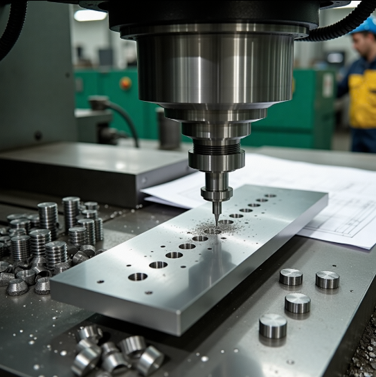
The transformation process begins with your CAD model—a digital blueprint defining every dimension, geometry, and functional requirement of your part. When you submit this file to a CNC prototype service, specialized software converts your design into machine-readable instructions that guide cutting tools with exceptional accuracy.
Here's what happens next: precision cnc machining equipment removes material from a solid block of metal or plastic, carving out your exact design layer by layer. The result? A cnc prototype that matches your digital specifications down to thousandths of an inch. Whether you're searching for cnc machine shops near me or evaluating online services, this fundamental process remains consistent across quality providers.
This bridge between digital design and physical reality is what makes cnc prototyping invaluable for product development teams. You're not approximating your design—you're manufacturing it.
Why Prototypes Demand Precision Manufacturing
There's a critical distinction between visual mockups and functional prototypes that many first-time developers miss. A mockup shows you what a product looks like. A prototype shows you how it works and feels.
Visual mockups are static representations—perfect for stakeholder presentations and aesthetic reviews. But when you need to test whether parts fit together, withstand stress, or perform under real operating conditions, you need functional machined parts made from actual production materials.
The quality of your prototype directly determines the accuracy of your design validation. Test with inferior materials or loose tolerances, and you'll make decisions based on flawed data—potentially approving designs that fail in production or rejecting concepts that would have succeeded.
This is precisely why engineers and product designers turn to precision manufacturing for prototypes. When a machinist near me or an online service delivers a cnc prototype, they're providing a test specimen that behaves exactly like your production part will. Aluminum prototypes flex and conduct heat like aluminum production parts. Steel prototypes handle loads like steel production parts.
For anyone researching whether CNC prototyping fits their project needs, consider this: if your prototype must demonstrate mechanical performance, thermal behavior, or assembly fit with other components, precision cnc machining isn't optional—it's essential. The data you gather from testing directly informs your go/no-go decision on production investment.
The Complete Prototype Journey from Design to Delivery
So you have a CAD file and you're ready to turn it into a physical prototype. What happens next? Understanding the complete workflow helps you prepare properly, make informed decisions at each checkpoint, and avoid delays that could push back your testing timeline.
Whether you're working with machining shops near me or partnering with an online service, the journey from digital file to finished cnc machining parts follows a predictable sequence. Let's walk through each stage so you know exactly what to expect.
- CAD file preparation and upload – Format your design files correctly and submit them through the service portal
- Design for manufacturability (DFM) review – Engineers analyze your design and provide feedback on potential issues
- Material and finish selection – Choose the right material and surface treatments for your prototype purpose
- Machining execution – Your part is manufactured on CNC equipment according to specifications
- Quality inspection – Finished parts undergo dimensional verification and quality checks
- Delivery – Packaging and shipping to your location
Each checkpoint requires specific decisions from you. Understanding these decision points upfront streamlines the process and helps you get accurate online machining quotes faster.
Preparing Your CAD Files for Submission
Your CAD file is the blueprint that guides every cut, drill, and contour on the finished part. Getting this right from the start prevents back-and-forth revisions that eat into your timeline.
Most CNC prototype services accept files in STEP (.stp) or IGES (.iges) formats. These universal file types translate accurately across different CAM software systems, ensuring the machining instructions match your design intent. Native CAD formats like SolidWorks or Fusion 360 files can work too, but converting to STEP typically provides the most reliable results.
Before uploading, run through this quick optimization checklist:
- Verify dimensions and units – Confirm your model uses the correct unit system (inches or millimeters)
- Check for surface errors – Repair any gaps, overlaps, or non-manifold geometry in your model
- Define critical tolerances – Mark which dimensions require tighter precision versus standard tolerances
- Include thread specifications – Specify thread types, sizes, and depths for any tapped holes
- Note surface finish requirements – Indicate areas needing specific roughness values or treatments
When you request a cnc quote online, complete and accurate files generate faster, more accurate pricing. Missing information triggers questions that delay your quote—and ultimately your parts.
The DFM Review That Saves Time and Money
Here's where experienced eyes catch problems before they become expensive mistakes. Design for manufacturability review is the checkpoint that separates smooth prototype projects from frustrating ones.
During DFM review, manufacturing engineers analyze your design against the practical realities of CNC machining. They're looking for features that might cause problems: internal corners that are too sharp for standard tooling, walls that are too thin to machine without distortion, or geometries that require special fixturing.
According to manufacturing experts at Cortex Design, "DFM is most valuable when it starts early in the design process. Incorporating good basic Design for Manufacturing principles into the design of your prototype parts before production helps prevent costly mistakes, reduces redesigns, and improves the chances of a smooth transition to large-scale manufacturing."
Common DFM feedback includes:
- Adding fillet radii to internal corners so standard end mills can reach them
- Increasing wall thickness to prevent deflection during cutting
- Adjusting hole depths to match standard drill lengths
- Modifying undercuts that would require special tooling
- Recommending material alternatives that machine more efficiently
Smart designers treat DFM feedback as collaborative input, not criticism. Local machine shops and online services alike want your project to succeed—their suggestions come from real manufacturing experience with thousands of custom machined parts.
From Machine to Your Door
Once machining is complete, your parts aren't quite ready to ship. Post-processing and quality verification ensure what arrives matches what you ordered.
Post-processing typically includes deburring—removing the sharp edges and burrs left by cutting tools. Depending on your requirements, additional treatments might include bead blasting for uniform matte surfaces, anodizing for aluminum parts, or various plating options for corrosion resistance.
Quality inspection verifies that your custom machined parts meet specifications. Using instruments like calipers, micrometers, and Coordinate Measuring Machines (CMMs), technicians check critical dimensions against your drawing. For precision machining parts, this step confirms that tight tolerances were achieved before the part leaves the facility.
Shipping considerations depend on your timeline and part requirements. Standard ground shipping works for most prototype projects, while expedited options are available when testing schedules are tight. Fragile or precision parts may require special packaging to prevent damage in transit.
The entire journey—from file upload to parts in hand—typically takes two to seven days depending on complexity and material availability. Understanding what happens at each stage helps you plan realistic timelines and communicate effectively with your manufacturing partner, whether that's a local shop or an online service specializing in rapid prototype delivery.
Choosing Materials That Validate Your Design
You've prepared your CAD file and understand the prototype journey. Now comes a decision that directly impacts whether your testing produces meaningful results: which material should you use?
Material selection for CNC prototypes goes far beyond picking something that "looks right." The material you choose determines how accurately your prototype represents final product performance. Test with the wrong material, and you'll gather data that misleads your design decisions. Test with the right one, and you'll validate exactly how your production parts will behave.
According to manufacturing experts at Timay CNC, "Selecting the appropriate material is essential for obtaining necessary attributes such as robustness, longevity, and accuracy in CNC prototypes. Testing with the exact material or a close substitute ensures accurate results."
Let's break down your options across metals and engineering plastics, then build a framework for making the right choice.
Metals That Match Production Intent
When your final product will be metal, prototyping with the same material family gives you the most reliable test data. But which metal fits your specific application?
Aluminum alloys dominate CNC prototype work for good reason. They're lightweight, highly machinable, and corrosion-resistant—making them ideal for aerospace components, automotive parts, and consumer electronics housings. Aluminum 6061 stands out as the workhorse alloy, offering excellent machinability and a great strength-to-weight ratio at moderate cost. For prototypes requiring anodizing or those headed toward production in aluminum, this is often your best starting point.
Stainless steel steps in when you need superior strength, wear resistance, or corrosion protection that aluminum can't deliver. Medical device prototypes, food processing equipment, and outdoor hardware often require stainless steel testing to validate performance in demanding environments. Expect longer machining times and higher costs, but the durability data you gather justifies the investment when your application demands it.
Brass offers a unique combination of easy machinability and aesthetic appeal. It's frequently chosen for decorative components, electrical connectors, and plumbing fixtures. If your prototype needs both functional testing and a polished visual appearance, brass delivers on both fronts without excessive machining costs.
Bronze CNC machining serves specialized applications where you need excellent wear resistance and low-friction properties. Bearings, bushings, and marine components often prototype in bronze to validate performance in sliding or rotating contact scenarios. While machining bronze requires attention to proper tooling and speeds, the material properties are difficult to replicate with substitutes.
For businesses targeting fast lead times, aluminum and brass are the go-to materials. As noted by industry specialists at JLCCNC, "For small-batch production or prototyping, materials like aluminum and brass reduce risk and cost due to shorter machine times and easier setups."
Engineering Plastics for Functional Testing
When your production parts will be plastic—or when you need lightweight, cost-effective prototypes for mechanical testing—engineering plastics offer compelling advantages.
Delrin (POM/Acetal) is the go-to choice for low-friction components. This delrin material excels in gears, bearings, and sliding mechanisms where smooth motion and dimensional stability are crucial. Delrin plastic machines beautifully, holding tight tolerances while delivering the stiffness needed for functional mechanical testing. If your prototype involves moving parts that contact other surfaces, delrin should be on your shortlist.
Acetal plastic—essentially another name for POM—shares these same properties. Whether your supplier calls it delrin, acetal, or POM, you're getting a material that combines excellent machinability with outstanding performance in wear applications.
Nylon for machining offers high strength, toughness, and thermal stability. It's commonly used for structural components, gears, and parts that must withstand repeated stress cycles. However, nylon absorbs moisture, which can cause dimensional changes over time. For applications exposed to humidity, this property matters—either plan for it or consider moisture-resistant alternatives.
Polycarbonate (PC) brings shatter resistance and heat resistance together with excellent optical clarity. Polycarbonate PC prototypes work well for protective covers, display windows, and components that must survive impact without breaking. In automotive and medical device applications, polycarbonate's toughness makes it invaluable for functional testing.
According to machining specialists at Hubs, "CNC machining plastics offers many advantages over metals. It is the preferred choice when a project requires lighter weight, lower cost, faster machining times, and less tool wear."
Matching Material to Prototype Purpose
Choosing between these options requires understanding what you're actually testing. Ask yourself three questions:
- What mechanical loads will the part experience? High-stress applications need materials with matching strength characteristics.
- What thermal environment will it operate in? Heat-sensitive applications require materials that maintain stability at operating temperatures.
- What's your budget constraint? Affordable options like ABS or aluminum often meet needs without premium material costs.
The following comparison table summarizes common prototype materials to help guide your decision:
| Material Type | Key Properties | Typical Applications | Relative Cost |
|---|---|---|---|
| Aluminum 6061 | Lightweight, excellent machinability, corrosion-resistant | Aerospace parts, automotive components, enclosures | Low-Medium |
| Stainless Steel | High strength, wear and corrosion resistance | Medical devices, food equipment, outdoor hardware | Medium-High |
| Brass | Easy machinability, aesthetic finish, corrosion-resistant | Electrical connectors, decorative parts, fittings | Medium |
| Bronze | Wear resistance, low friction, marine-grade durability | Bearings, bushings, marine components | Medium-High |
| Delrin (POM/Acetal) | Low friction, dimensional stability, stiffness | Gears, bearings, sliding mechanisms | Low-Medium |
| Nylon | High strength, toughness, thermal stability | Structural parts, gears, bushings | Low |
| Polycarbonate (PC) | Shatter-resistant, heat-resistant, optical clarity | Protective covers, display windows, automotive parts | Low-Medium |
When your prototype must match production material exactly, the choice is straightforward—use the same material. But when you're testing form and fit rather than material-specific performance, cost-effective substitutes can deliver valid results at lower expense.
The bottom line? Match your material selection to your testing objectives. A prototype meant to validate assembly fit can use affordable aluminum even if production will be stainless steel. But a prototype meant to validate corrosion resistance or thermal performance must use the actual production material to generate meaningful data.
With material selection clarified, the next critical decision involves understanding which machining process your part geometry actually requires—and how that choice affects both cost and capability.
Matching Machining Processes to Part Complexity
You've selected your material. Now comes a question that directly impacts both cost and capability: which machining process does your prototype actually need?
Here's the reality—many first-time prototypers request advanced 5 axis cnc machining services when simpler processes would deliver identical results at lower cost. Others underestimate their part's complexity and face surprise quotes or manufacturability issues. Understanding the right match between your geometry and the machining method helps you avoid both pitfalls.
Let's break down the three primary CNC process categories and when each makes sense for prototype work.
When 3-Axis Milling Gets the Job Done
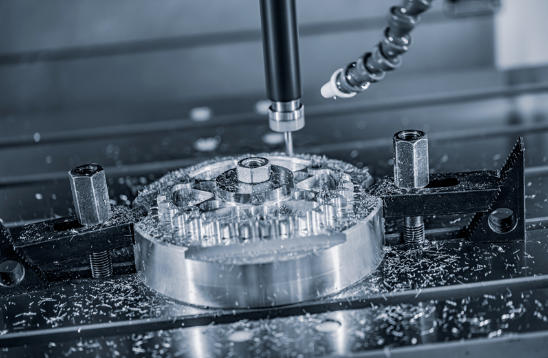
For most prototype parts, 3-axis cnc machining milling provides everything you need. The cutting tool moves along three linear directions—side to side, front to back, and up and down—relative to a fixed workpiece. This straightforward motion handles the vast majority of cnc milled components without added complexity or expense.
Think about it: if your part has features that can all be accessed from a single direction (or with simple repositioning), 3-axis milling delivers excellent precision at the most competitive price point.
Part characteristics suited for 3-axis milling:
- Flat surfaces and 2D profiles that can be cut from one orientation
- Pockets, slots, and holes perpendicular to the top surface
- Parts where multiple setups (repositioning the workpiece) are acceptable
- Components with features on the same plane or parallel planes
- Enclosures, panels, brackets, and mounting plates
The limitation? If your design includes angled features or undercuts that can't be reached from above, you'll either need multiple setups (adding time and potential alignment errors) or a more advanced process. But for sheet-style parts, housings, and components with accessible top-side geometry, 3-axis cnc cutting remains the most cost-effective choice.
CNC Turning for Rotational Components
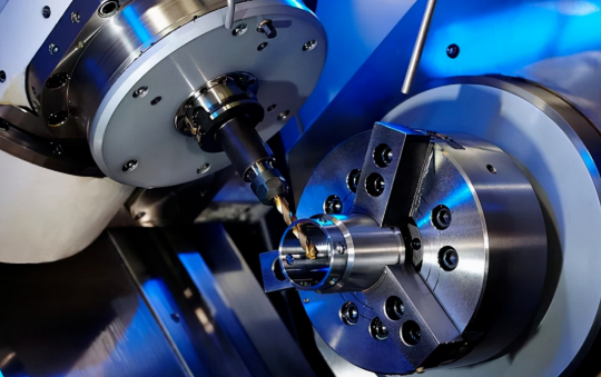
When your prototype is cylindrical, conical, or features rotational symmetry, cnc turning becomes your go-to process. Unlike milling where the tool rotates, turning spins the workpiece itself while a stationary cutting tool shapes the material.
This fundamental difference makes turning exceptionally efficient for shafts, pins, bushings, and threaded components. As noted by machining specialists at 3ERP, "CNC turning is especially effective when you're producing components with rotational symmetry—like rods, discs, shafts, or bushings. It provides excellent concentricity, roundness, and dimensional accuracy."
Part characteristics suited for cnc turning:
- Round or cylindrical shapes with symmetry around a central axis
- Components requiring external diameters, internal bores, or both
- Threaded features (external or internal threads)
- Grooves, chamfers, and tapers along the rotational axis
- Parts starting from bar stock (rods, tubes)
Modern cnc turning service providers often equip their machines with live tooling—rotating cutters that can add milled features like flats, holes, or keyways without moving the part to a separate machine. This capability makes cnc turned parts more versatile than traditional lathework, often eliminating secondary operations entirely.
The cost advantage of turning for appropriate geometries is significant. Because the process is streamlined for rotational forms, cycle times drop and per-part pricing follows.
Multi-Axis Machining for Complex Geometries
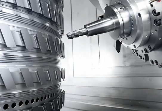
When your prototype includes compound angles, organic contours, or features that simply can't be reached with 3-axis motion, multi-axis machining enters the picture. Adding a fourth or fifth axis allows either the workpiece or the cutting tool to rotate during machining, reaching otherwise inaccessible areas in a single setup.
According to machining experts at DATRON, "More complex geometries, like arcs and helixes, can be achieved more efficiently with 4th and 5th axis machining. You're also able to cut angled features more easily."
Part characteristics requiring 4-axis or 5-axis machining:
- Features on multiple non-parallel faces that must maintain tight positional tolerances
- Undercuts, compound angles, or sculptured surfaces
- Aerospace components like turbine blades or impellers
- Medical implants with organic contoured shapes
- Parts where eliminating multiple setups improves accuracy
Here's the cost reality: 5 axis cnc machining services carry premium pricing. Machine hourly rates are higher, programming is more complex, and setup requires greater expertise. But for parts that truly need multi-axis capability, the alternative—multiple repositioning operations with alignment errors compounding at each step—often costs more in the end while delivering inferior results.
The smart approach? Start by evaluating whether your geometry genuinely requires advanced capability. Many parts designed with dramatic angles or complex contours can be simplified during DFM review to enable 3-axis machining without sacrificing function. When complexity is essential to your design, multi-axis machining delivers precision that simpler processes simply cannot match.
Understanding which process your prototype requires prevents both over-engineering (paying for capability you don't need) and under-specifying (discovering mid-project that your geometry demands more). With process selection clarified, the next consideration—tolerance specification—determines how precise your prototype needs to be and what that precision actually costs.
Tolerance Decisions That Balance Precision and Budget
You've selected your material and machining process. Now comes a specification decision that trips up more first-time prototypers than almost any other: how tight should your tolerances be?
Here's what manufacturing engineers consistently observe: many prototype drawings arrive with unnecessarily strict tolerances applied uniformly across every dimension. The assumption? Tighter must mean better. The reality? Over-tolerancing inflates costs dramatically without improving functionality—sometimes doubling or tripling your prototype budget for precision you don't actually need.
Understanding when tight tolerances matter versus when standard tolerances suffice helps you invest your precision budget where it delivers real value. Let's break down the practical guidance that keeps your cnc machine parts functional and affordable.
Standard Tolerances That Work for Most Prototypes
Most precision machining services offer standard tolerances that handle the vast majority of prototype requirements without special callouts. According to Protolabs' tolerancing guidelines, typical CNC machining achieves ±0.005 in. (±0.127 mm) on standard features—precision that exceeds what most prototype applications demand.
What does this mean practically? For general dimensions—overall lengths, pocket depths, non-critical hole locations—standard tolerances deliver reliable, repeatable results. Your parts will match your CAD model closely enough for assembly testing, fit checks, and most functional validation.
Surface roughness follows similar principles. Standard CNC finishing typically achieves 63 µin. for flat surfaces and 125 µin. for curved surfaces. Unless your prototype requires specific sealing surfaces or cosmetic finishes, these standard values work without additional specification or cost.
Precision machining parts don't require tight tolerances everywhere—they require tight tolerances where they matter. Identifying those critical dimensions separates cost-effective prototyping from budget-busting over-specification.
When Tight Tolerances Actually Matter
So when should you specify tighter precision? Focus on functional interfaces—the dimensions that directly affect whether your prototype performs its intended purpose.
Mating surfaces and assembly fits often require controlled tolerances. When two parts must slide together, press-fit, or align precisely, the interface dimensions need specification beyond standard values. Consider what is the tolerance for thread holes in your assembly—if you're designing a through hole for a 4 m bolt, the clearance must accommodate fastener insertion while maintaining positional accuracy.
Threaded features demand attention to established standards. When specifying connections like 3/8 npt thread dimensions or calculating 1 4 npt hole size requirements, the precision machining services you work with need clear callouts to ensure proper sealing and engagement. Thread tolerances follow industry standards that your machining partner understands—but you must specify which standard applies.
Critical moving interfaces benefit from tighter control. Bearing bores, shaft diameters, and sliding mechanisms typically require tolerances in the ±0.001 in. to ±0.002 in. range to ensure smooth operation and proper clearance.
According to manufacturing experts at RPWORLD, "Tight part tolerances only indicate a high production quality for individual parts, and do not directly equate to higher product quality. Product quality is ultimately presented through the assembly of parts."
The takeaway? Apply tight tolerances selectively to dimensions that genuinely affect function. Everything else can use standard values without compromising your prototype's validity.
The Hidden Cost of Over-Tolerancing
Why does unnecessary precision specification hurt your budget so significantly? The answer lies in manufacturing economics.
Tight tolerances require slower cutting speeds, more frequent tool changes, additional inspection steps, and sometimes secondary operations like grinding. Each requirement adds time—and time drives cost. As noted by tolerance specialists at Modus Advanced, CNC machining typically achieves ±0.001 in. to ±0.005 in. (±0.025 to ±0.127 mm), but pushing toward the tighter end of that range dramatically increases manufacturing complexity.
Consider this comparison of tolerance ranges and their practical implications:
| Tolerance Range | Typical Applications | Cost Impact | Lead Time Impact |
|---|---|---|---|
| ±0.010 in. (±0.254 mm) | Non-critical dimensions, general features | Baseline (1x) | Standard |
| ±0.005 in. (±0.127 mm) | Standard machining, most prototype features | 1.2x–1.5x | Standard |
| ±0.002 in. (±0.051 mm) | Functional interfaces, mating parts | 1.5x–2x | +1–2 days |
| ±0.001 in. (±0.025 mm) | Precision bearings, critical alignments | 2x–3x | +2–3 days |
| ±0.0005 in. (±0.013 mm) | Aerospace/medical critical features | 3x–5x+ | +3–5 days, may require grinding |
The relationship is non-linear. Moving from ±0.005 in. to ±0.002 in. might add 50% to your cost. Pushing to ±0.001 in. could double it. And demanding ±0.0005 in. on multiple features might triple your budget while adding days to your timeline.
Smart tolerance specification follows a simple principle: identify the critical dimensions that affect function, apply appropriate precision to those features, and let everything else default to standard values. Your precision machining parts will perform exactly as needed—without paying for precision that adds no value.
With tolerance strategy clarified, you're ready to consider something many prototypers overlook until it's too late: how your prototype design decisions today affect your ability to scale into production tomorrow.
Planning Your Path from Prototype to Production
Here's a scenario that catches many product developers off guard: your prototype passes every test with flying colors, stakeholders approve moving forward, and then you discover that scaling to production requires costly redesigns. The part that worked perfectly as a one-off becomes problematic at volume.
This transition gap—from validated prototype to scalable production—represents one of the most underestimated challenges in product development. Yet it's entirely avoidable when you plan for production from the very first prototype iteration.
According to manufacturing experts at Fictiv, "There can be big differences between engineering a product for prototype and engineering the product for manufacturing, and good manufacturing partners should bring this level of acumen to the table, including design for manufacturability (DFM) and design for supply chain (DfSC) expertise."
Let's explore how to bridge this gap effectively—starting with decisions you can make today that pay dividends when production volumes arrive.
Designing Prototypes with Production in Mind
The smartest cnc machining prototyping approach treats every prototype as a stepping stone toward production, not just a validation checkpoint. This mindset shift influences material selection, feature design, and tolerance specification from day one.
What does production-minded prototype design actually look like?
Material alignment matters. When possible, prototype with materials that closely match your intended production materials. Testing aluminum 6061 when you plan to produce in aluminum 6061 gives you data that translates directly. Substituting materials for cost savings during prototyping can work—but only when you understand how material differences might affect your validation conclusions.
Simplify where function allows. Every feature that complicates machining at prototype scale becomes exponentially more challenging at volume. Ask yourself: does this geometric complexity serve a functional purpose, or did it creep into the design for aesthetic or historical reasons? Reducing part count and eliminating unnecessary features now prevents manufacturing headaches later.
Standardize components strategically. Using readily available, standard fasteners, bearings, and hardware components ensures your production supply chain won't hit sourcing bottlenecks. Custom components might seem ideal during prototyping, but they create dependencies that slow scaling.
As noted by manufacturing specialists at H&H Molds, "Implementing DFM principles early can drastically reduce production issues later. This means simplifying designs by reducing part count and complexity whenever possible."
The goal isn't constraining creativity—it's channeling innovation toward solutions that work at any volume.
What Changes Between Prototype and Production Runs
Even with careful planning, the transition from prototype machining to production manufacturing typically involves modifications. Understanding these common changes helps you anticipate and budget for them.
Tooling investments scale up. Prototype runs often use general-purpose tooling and fixtures. Production runs justify custom fixtures, optimized tool paths, and dedicated setups that reduce cycle times. This upfront investment pays back through lower per-part costs at volume.
Quality systems formalize. During prototyping, inspection might be thorough but informal—an engineer checking critical dimensions manually. Production demands documented quality control procedures, statistical sampling plans, and consistent inspection protocols. As Fictiv's manufacturing team notes, "Quality control systems need implementation to maintain consistency, and supply chain management becomes crucial for establishing reliable sourcing of components and materials."
Assembly processes evolve. Hand-assembling prototypes works fine for small quantities. But scaling to production often means transitioning from manual assembly to automated or semi-automated processes. Features that were easy to assemble by hand might require redesign to accommodate robotic assembly or faster manual workflows.
Tolerance refinement occurs. Production experience often reveals which tolerances are genuinely critical and which can be relaxed. Some features tightened during prototyping prove unnecessary at scale; others that seemed acceptable cause assembly issues at volume. Expect tolerance specifications to evolve based on production data.
According to cnc fabrication experts at H&H Molds, "The transition involves a series of steps to ensure the design is optimized, the manufacturing process is established, and the product can be produced at scale while maintaining quality and reliability."
These changes aren't failures of prototype planning—they're natural evolution as manufacturing knowledge deepens through production experience.
Finding Partners Who Support the Full Journey
Here's where partner selection becomes strategic rather than transactional. Working with a manufacturing partner capable of both cnc prototype machining and production volumes creates continuity that standalone prototype shops cannot provide.
Why does this continuity matter?
- Knowledge transfer happens automatically. The engineers who machined your prototypes understand your design intent intimately. That institutional knowledge carries forward into production without documentation gaps or interpretation errors.
- Quality standards remain consistent. When the same facility handles prototypes and production, quality expectations don't shift between phases. What passed inspection during prototyping will pass during production—no surprises.
- Scaling becomes predictable. Partners experienced in both phases can forecast production challenges during prototyping, providing DFM feedback that anticipates scaling issues before they occur.
For automotive applications specifically, this partner selection carries additional weight. IATF 16949 certification—the automotive industry's quality management standard—signals a facility's capability to maintain rigorous quality control from prototype through high-volume production.
Facilities like Shaoyi Metal Technology demonstrate this integrated capability, offering custom cnc machining services that scale seamlessly from rapid prototyping to mass production. Their IATF 16949 certification and Statistical Process Control (SPC) implementation ensure consistent quality as volumes increase—critical for automotive supply chains where tolerance drift can cascade into assembly line disruptions.
When evaluating potential partners, consider these indicators of production-ready capability:
- Certifications appropriate to your industry (IATF 16949 for automotive, AS9100 for aerospace, ISO 13485 for medical)
- Demonstrated experience scaling from prototype quantities to production volumes
- Established quality management systems with documented process controls
- Capacity to handle your projected production volumes without outsourcing
- Engineering support that extends beyond quoting into DFM collaboration
According to manufacturing partnership experts at Fabrication Concepts, "Working with an experienced manufacturing partner from the outset offers a streamlined path for parts procurement through the product development process and helps mitigate risk down the road."
The bottom line? Your prototype partner choice today shapes your production options tomorrow. Selecting a partner with proven scaling capability—and the certifications to prove it—transforms the prototype-to-production transition from a risk-laden gap into a managed progression.
With production planning addressed, the next consideration turns practical: understanding what drives prototype costs and how to optimize your budget without compromising the validation data you need.
Understanding Prototype Pricing and Cost Optimization
You've made your design decisions, selected materials, and specified tolerances. Now comes the question every product developer asks: what will this actually cost?
Here's the honest truth—cnc machining price varies dramatically based on factors you can control. A simple aluminum bracket might run $100-$200, while a complex multi-feature component in specialty steel could exceed $1,000. Understanding what drives these differences helps you set realistic budgets and identify opportunities to optimize costs without sacrificing prototype quality.
According to manufacturing cost analysts at Hotean, "The average cost of CNC prototyping ranges from $100-$1,000 per part depending on complexity, material choice, and required tolerances. Design complexity alone can increase machining time by 30-50%, directly impacting your final bill."
Let's break down exactly where your money goes—and how to spend it wisely.
What Actually Drives Prototype Costs
Five primary factors determine what you'll pay for cnc parts. Understanding each helps you make informed tradeoffs during the design phase.
Material costs set your baseline. Raw material prices vary significantly across options. Aluminum typically costs 30-50% less to machine than stainless steel, while engineering plastics like ABS offer even greater savings for non-structural applications. But material cost isn't just about raw price—machinability matters too. Harder materials like titanium require slower cutting speeds, more tool changes, and increased wear on cutting tools. All of that adds machining parts expense beyond the material invoice.
Complexity multiplies machine time. Every additional feature, contour, and pocket requires programming, tool changes, and cutting operations. According to Dadesin's cost analysis, "The more complex a prototype, the longer it takes to machine—leading to higher costs." Intricate geometries with tight internal corners, deep pockets, or multi-axis features can push machining time 30-50% beyond simpler designs with equivalent dimensions.
Tolerances add precision costs. As covered earlier, tight tolerances require slower speeds, additional passes, and more rigorous inspection. Specifying ±0.0005" where ±0.005" would suffice can increase costs by 30-50%. The inspection equipment itself becomes more sophisticated—and expensive—as precision requirements tighten.
Setup charges apply regardless of quantity. Programming the machine, creating fixtures, and preparing tool paths represent fixed costs that apply whether you're ordering one part or ten. For small cnc machining orders, these setup costs dominate the per-unit price. As UIDEARP's cost guide explains, "Each extra setup orientation significantly raises the cost" since parts requiring repositioning multiply these fixed expenses.
Post-processing adds finishing expenses. Basic deburring adds minimal cost, but premium finishes escalate quickly. Bead blasting adds $10-$20 per part, anodizing runs $25-$50, and specialized coatings like powder coating add $30-$70 depending on part size. For aesthetic prototypes, these treatments can approach or exceed the base machining cost.
Quantity Economics in Prototype Runs
Here's where understanding cnc service economics really pays off: ordering smart quantities can dramatically reduce your per-unit investment.
Why do costs drop so significantly with quantity? Those fixed costs—programming, setup, fixture creation—spread across more units. A single prototype absorbs the entire setup charge. Order five units, and each part carries only one-fifth of that burden.
According to cost analysis from Hotean, "A single prototype might cost $500, while ordering 10 units drops the per-piece price to approximately $300 each. For larger runs of 50+ units, costs can decrease by up to 60%, bringing per-unit prices down to around $120 while maintaining identical quality and specifications."
Consider this practical application: if you need prototypes for testing, stakeholder review, and a spare for destructive testing, ordering three to five units initially costs significantly less per part than ordering them separately. You gain redundancy for testing while substantially reducing per-unit investment.
Material purchasing also benefits from volume. Suppliers offer bulk discounts of 10-25% at higher quantities, and efficient material utilization reduces waste. What looks like a modest quantity increase can deliver outsized cost benefits.
Speed Versus Budget Tradeoffs
Tight timelines come with price tags. Rapid cnc prototyping services offering expedited turnaround typically charge premiums of 25-100% above standard pricing.
Why the premium? Rush orders disrupt scheduled production, require overtime labor, and may demand priority material sourcing. As UIDEARP notes, "Rush orders that need to be produced more quickly usually come with premium fees that are 25-100% more than normal prices."
Standard lead times—typically 7-10 days—allow manufacturers to optimize scheduling, batch similar operations, and maintain efficient workflows. Compressing that timeline to 1-3 days forces inefficiencies that translate directly to higher costs.
The smart approach? Plan ahead whenever possible. Build prototype lead times into your project schedule, and reserve expedited options for genuine emergencies rather than routine orders.
For those seeking to maximize budget efficiency without compromising prototype quality, consider these proven cost reduction strategies:
- Simplify non-critical features – Reduce complexity in areas that don't affect functional testing
- Specify tolerances strategically – Apply tight tolerances only where function demands them
- Choose cost-effective materials – Use aluminum instead of steel when material properties aren't critical to testing
- Order in small batches – Even 3-5 units dramatically reduces per-part costs versus single prototypes
- Allow standard lead times – Avoid rush premiums by planning prototype phases into your schedule
- Minimize setup orientations – Design parts accessible from fewer directions to reduce repositioning
- Match finishes to purpose – Use as-machined surfaces for functional testing; reserve premium finishes for presentation prototypes
The bottom line? CNC prototype costs aren't fixed—they respond directly to decisions you control. By understanding what drives pricing and making intentional choices about complexity, tolerance, quantity, and timing, you can stretch your prototype budget significantly further without compromising the validation data you need.
Of course, even the best-planned prototype projects can stumble over avoidable mistakes. Let's look at the common pitfalls first-time prototypers encounter—and how to sidestep them entirely.
Avoiding First-Time Prototyping Pitfalls
You've done your research on materials, tolerances, and costs. You're ready to submit your first CNC prototype order. But here's what experienced engineers know that first-timers often learn the hard way: preventable mistakes derail more prototype projects than technical complexity ever does.
Think of this section as mentorship from someone who's seen hundreds of prototype projects succeed—and watched others stumble over avoidable errors. Whether you're searching for a cnc machine shop near me or working with an online service, these pitfalls apply universally. Understanding them upfront saves you time, money, and frustration.
According to manufacturing specialists at Zenith Manufacturing, the hidden costs of file errors are catastrophic for projects: "That '30-minute fix' just caused a two-week delay as you wait for the next available machine slot." Let's make sure that doesn't happen to you.
Design Mistakes That Delay Your Timeline
CAD software lets you design anything—but CNC machines can't manufacture everything. This disconnect between digital freedom and physical reality causes the most common first-time errors.
Sharp internal corners top the list. Your CAD model shows perfect 90-degree internal corners because that's what you drew. But rotating cutting tools are round—they physically cannot create zero-radius internal corners. As Uptive Manufacturing explains, "Sharp corners create localized stress points that can result in premature failure and negatively impact the overall performance of the machined part."
The fix? Add fillet radii to internal corners that match or exceed your machining partner's standard tool sizes. Radii of R=1, 2, 3, 4, or 5mm align with standard end mills and eliminate this issue entirely.
Thin walls create machining nightmares. Walls that look fine on screen may vibrate, flex, or even break during cutting. CNC plastic machining is particularly vulnerable—plastic walls need more thickness than metal to resist tool pressure. As a general rule, keep walls at least 0.8mm thick for metals and 1.5mm for plastics.
Unnecessarily complex geometries inflate costs. Every compound curve, deep pocket, and angled feature adds programming time, tool changes, and machining passes. According to Uptive's design guide, "Overly complex designs may not contribute any functional value to the part, leading to inefficiencies and potential manufacturing challenges." Before submitting, ask yourself: does each feature serve a functional purpose?
File format and unit errors waste everyone's time. Submitting files in the wrong units (inches interpreted as millimeters or vice versa) is embarrassingly common—and completely preventable. As Zenith Manufacturing notes, this creates pure waste: "Your vendor's engineer opens your file, ready to quote your 2-foot-wide enclosure. Instead, they see a model that is the size of a fingernail."
Always verify your export settings before submission. Use STEP format for maximum compatibility, and double-check that your units match your drawing specifications.
Material Selection Errors That Compromise Testing
Choosing the wrong material doesn't just waste money—it generates misleading test data that can derail your entire product development.
Testing with substitute materials when properties matter. Prototyping a stainless steel component in aluminum because it's cheaper works fine for form and fit checks. But if you're testing corrosion resistance, thermal behavior, or wear characteristics, that aluminum prototype tells you nothing useful about production performance. Match your cnc machining materials to your testing objectives.
Ignoring machinability in material selection. Some materials machine beautifully; others fight every cut. According to Uptive Manufacturing, "Neglecting to assess machinability can result in difficulties such as increased tool wear, extended production times, and overall inefficiencies in the CNC machining process." If you're unfamiliar with how a material machines, ask your manufacturing partner before finalizing your order.
Overlooking material-specific design requirements. Different materials demand different design approaches. Thin features that work in aluminum may fail in brittle materials. Cnc milling parts from plastics require attention to heat buildup that metals handle easily. A custom machine shop experienced with your chosen material can flag these issues during DFM review—but only if you select materials before finalizing your design.
Communication Gaps That Lead to Surprises
Even perfect CAD files can produce disappointing results when communication breaks down between you and your manufacturing partner.
Sending only 3D models without drawings. Your STEP file defines geometry perfectly—but it doesn't communicate intent. Which surfaces are critical? What tolerances matter? Where should inspection focus? As Zenith Manufacturing emphasizes, "The 3D model defines the geometry, but it fails to define the intent." Always include a 2D drawing that calls out critical dimensions, tolerances, and finish requirements.
Failing to ask for DFM feedback. Many first-timers treat machinist shops near me as order-takers rather than engineering partners. That's a missed opportunity. A simple question—"What modifications would you recommend to reduce cost and improve manufacturability?"—invites expertise that can save significant time and money.
Assuming quotes equal manufacturability approval. An instant online quote confirms price, not manufacturability. The real analysis often happens after you place the order, when a human engineer reviews your files. Surprises at this stage trigger delays or price adjustments. As Zenith warns, "Never equate an 'instant quote' with a 'manufacturability analysis.' A good partner will proactively point out problems with their quote."
Before submitting your next prototype order, run through this pre-submission checklist to catch common issues before they cause delays:
- File format verified – Export as STEP (.stp) for maximum compatibility
- Units confirmed – Double-check inches vs. millimeters in export settings
- Geometry validated – Run your CAD software's repair tool to fix non-manifold errors
- Internal radii added – Ensure all internal corners have radii matching standard tool sizes (R=1, 2, 3mm, etc.)
- Wall thickness checked – Confirm minimum 0.8mm for metals, 1.5mm for plastics
- 2D drawing included – Specify critical dimensions, tolerances, and surface finish requirements
- Material specified clearly – Include grade and any heat treatment or certification requirements
- Thread callouts complete – Specify thread type, size, pitch, and depth for all tapped holes
- Tolerances reviewed – Apply tight tolerances only where function requires them
- DFM feedback requested – Ask your partner for manufacturability recommendations
Following this checklist won't guarantee perfect prototypes—but it eliminates the most common causes of delays, rework, and budget overruns. With these fundamentals covered, you're ready to evaluate potential manufacturing partners and select the right one for your specific prototype needs.
Selecting Your CNC Prototype Partner
You've mastered the fundamentals—materials, tolerances, processes, and cost optimization. Now comes the decision that pulls everything together: choosing the right manufacturing partner to bring your prototype to life.
This choice matters more than most first-time prototypers realize. The best CAD file in the world means nothing if your manufacturing partner lacks the capability, communication skills, or quality systems to execute it properly. Conversely, the right partner transforms even challenging projects into smooth, successful prototype runs.
Let's examine what separates exceptional cnc machined parts providers from average ones—and help you make a confident selection.
Evaluating Service Provider Capabilities
Not all precision cnc machining services deliver equal results. Beyond basic pricing, several factors distinguish partners who consistently deliver from those who create headaches.
Certifications signal commitment to quality. For aerospace cnc machining applications, look for AS9100 certification—the aerospace industry's quality management standard. Medical machining demands ISO 13485 compliance, ensuring parts meet stringent healthcare requirements. According to NSF's certification overview, IATF 16949 certification is particularly critical for automotive applications, representing "the international standard for automotive quality management systems" with emphasis on "prevention of defects and the reduction of variation and waste."
These certifications aren't just badges—they represent documented quality management systems, regular third-party audits, and organizational commitment to continuous improvement. As noted by manufacturing experts at 3ERP, "Quality assurance is a non-negotiable aspect when choosing a CNC machining service. Look for companies with recognized certifications, such as ISO 9001, which is a standard for quality management systems."
Equipment capabilities match project requirements. Does the facility have the machine types your parts require? Cnc turning services need lathes with appropriate capacity. Complex geometries demand multi-axis machining centers. According to 3ERP's selection guide, "A CNC machining service is only as effective as the tools at its disposal. Whether it's lathes, mills, or routers, the variety and quality of machinery can make or break your project."
Communication quality predicts project success. How responsive are they during the quoting process? Do they ask clarifying questions that demonstrate understanding of your project? A partner who communicates poorly before receiving your order will likely communicate worse after. As the same source notes, "Communication is the backbone of any successful partnership. An effective communication process means the service provider can promptly address your queries, update you on progress, and quickly rectify any issues."
Experience in your industry matters. A facility experienced in aerospace machining understands aerospace tolerances and documentation requirements. A partner with medical device experience knows FDA compliance expectations. Industry-specific experience translates to fewer learning-curve issues on your project.
When CNC Prototyping Is Not Your Best Option
Here's something most CNC providers won't tell you: sometimes CNC prototyping isn't your best choice. Honest assessment of alternatives builds trust—and helps you make better decisions.
3D printing excels where CNC struggles. According to analysis from JLC3DP, "3D printing allows for the creation of complex geometries, intricate details, and internal structures that may be challenging or impossible to achieve with CNC." If your prototype features internal lattices, organic shapes, or geometries that would require extensive multi-axis work, additive manufacturing may deliver faster results at lower cost.
Consider the precision tradeoff. CNC machining typically achieves tolerances of ±0.05mm or tighter, while 3D printing generally ranges from ±0.2mm to ±0.3mm. For prototype machining services where tight tolerances matter—functional interfaces, mating surfaces, precision fits—CNC remains the clear choice. But for visual prototypes, early concept models, or parts where precision isn't critical, 3D printing offers compelling advantages.
Material requirements often decide the question. If your prototype must use production-grade metals or specific engineering plastics to validate real-world performance, CNC machining is likely your path. As JLC3DP notes, "CNC machines can work with a vast array of materials, including metals, plastics, composites, wood, and more," while 3D printing remains "limited by the materials that are compatible with the specific 3D printing technology being used."
Volume economics favor different approaches. For single prototypes of simple geometries, 3D printing may be more economical. For batches of 5-50 precision parts, CNC machining typically wins on per-unit cost and quality consistency. Understanding where your project falls on this spectrum guides the right choice.
Taking Your First Step Forward
Ready to move from research to action? Here's how to proceed with confidence.
Start with your requirements, not your solution. Before contacting providers, document what you actually need: material type, approximate tolerances, quantity, timeline, and intended use. This clarity enables accurate quotes and meaningful DFM feedback.
Request quotes from multiple providers. Comparing responses reveals not just pricing differences but communication quality, technical understanding, and attention to detail. The provider asking smart questions about your project often delivers better results than the one offering the lowest price with no questions asked.
Evaluate scalability if production is your goal. For automotive applications specifically, partners with IATF 16949 certification offer seamless scaling from prototype to mass production. Facilities like Shaoyi Metal Technology demonstrate this capability, delivering high-tolerance components with lead times as fast as one working day while maintaining the quality systems required for automotive supply chains. Their Statistical Process Control implementation ensures consistency from first prototype through production volumes.
When evaluating potential partners, prioritize these key selection criteria:
- Relevant certifications – IATF 16949 for automotive, AS9100 for aerospace, ISO 13485 for medical devices
- Appropriate equipment – Machine capabilities matching your part geometry and material requirements
- Demonstrated experience – Portfolio or case studies showing work similar to your project
- Communication responsiveness – Quick, thoughtful responses during the quoting process
- DFM collaboration willingness – Partners who offer manufacturability feedback, not just order processing
- Scalability capability – Ability to grow with your project from prototype through production
- Quality documentation – Inspection reports, material certifications, and traceability as needed
- Realistic lead times – Timelines that match your schedule with expedite options when needed
The journey from CAD file to finished prototype doesn't have to be complicated. With the knowledge you've gained—understanding materials, processes, tolerances, costs, and common pitfalls—you're equipped to navigate the process confidently. The right manufacturing partner transforms that knowledge into physical parts that validate your design and accelerate your product development.
Your next step? Take that prepared CAD file, apply the DFM principles you've learned, and reach out to a qualified provider. The prototype that proves your concept is closer than you think.
CNC Machining Prototype Service FAQs
1. How much does a CNC prototype cost?
CNC prototype costs typically range from $100 to $1,000+ per part, depending on complexity, material choice, tolerances, and quantity. Simple aluminum parts start around $100-$200, while complex multi-feature components in specialty metals with tight tolerances can exceed $1,000. Key cost drivers include machining time, material prices, setup charges, and post-processing requirements. Ordering small batches of 3-5 units significantly reduces per-part costs since fixed setup expenses spread across more units.
2. How much does CNC machining service cost per hour?
CNC machining service rates typically range from $30 to $200 per hour depending on machine type and complexity. Standard 3-axis milling generally costs $30-$75 per hour, while advanced 5-axis CNC machining commands rates of $100-$200 per hour due to higher equipment costs and specialized programming requirements. Operator labor, material costs, and setup time are factored into final quotes rather than billed separately in most prototype services.
3. What file formats are accepted for CNC prototype orders?
Most CNC prototype services accept STEP (.stp) and IGES (.iges) files as universal formats that translate accurately across different CAM software systems. Native CAD formats from SolidWorks, Fusion 360, or Inventor can also work, but STEP typically provides the most reliable results. Always include a 2D drawing specifying critical dimensions, tolerances, thread specifications, and surface finish requirements since 3D files define geometry but not manufacturing intent.
4. How long does CNC prototype manufacturing take?
Standard CNC prototype lead times range from 3-10 business days depending on part complexity, material availability, and service provider capacity. Expedited services can deliver parts in as fast as 1-3 days, though rush orders typically carry 25-100% premium charges. Complex multi-axis parts, tight tolerances requiring additional inspection, or specialty materials may extend timelines. Planning ahead and allowing standard lead times helps avoid premium expedite fees.
5. What is the difference between CNC machining and 3D printing for prototypes?
CNC machining removes material from solid blocks to create parts with tighter tolerances (±0.05mm vs ±0.2-0.3mm for 3D printing), superior surface finishes, and production-grade material properties. 3D printing excels at complex internal geometries and organic shapes that would be difficult or impossible to machine. CNC prototypes are ideal when you need functional testing with actual production materials, precise mating surfaces, or validation of mechanical performance characteristics.