 Small batches, high standards. Our rapid prototyping service makes validation faster and easier —

CNC Machines Parts Decoded: What Keeps Your Spindle Spinning
Understanding CNC Machine Parts and Their Critical Roles
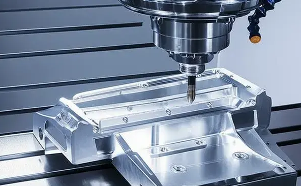
Imagine a machine capable of carving intricate aerospace components with tolerances tighter than a human hair—all while running unattended through the night. This remarkable precision doesn't happen by accident. Behind every flawless cut lies a symphony of carefully engineered CNC machines parts working in perfect harmony.
Whether you're an operator seeking to troubleshoot issues faster, a buyer evaluating your next equipment investment, or maintenance personnel aiming to extend machine life, understanding these components transforms how you interact with this technology. When you recognize how parts of a machine interconnect, you move from simply operating equipment to truly mastering it.
Why Every Component Matters in CNC Performance
Here's something many beginners overlook: a CNC machine is only as strong as its weakest component. A worn ball screw can introduce positioning errors that ripple through every part you produce. A failing spindle bearing might seem minor until surface finish quality plummets. Even auxiliary systems like coolant filtration directly impact tool life and dimensional accuracy.
This interconnected reality means that understanding CNC machine parts isn't optional—it's essential. According to industry experience, operators who grasp component functions can often identify problems before they escalate, potentially saving thousands in emergency repairs and scrapped parts.
The Five Functional Categories of CNC Parts
Rather than memorizing a random list of components, think of CNC components through a functional lens. This approach helps you understand not just what each part does, but how it contributes to the machine's overall mission of transforming raw material into finished products.
- Structural Components: The machine bed, frame, and column form the rigid foundation that absorbs vibrations and maintains geometric accuracy. Without this stable platform, precision machining becomes impossible.
- Motion Control Systems: Ball screws, linear guides, servo motors, and drives work together to translate digital commands into precise physical movements along multiple axes.
- Control Electronics: The controller (often called the machine's brain), feedback devices, and safety systems interpret G-code and coordinate every machine action in real-time.
- Tool Management: Spindles, tool holders, chucks, and automatic tool changers handle the cutting tools that actually remove material from your workpiece.
- Auxiliary Systems: Coolant delivery, chip conveyors, lubrication circuits, and hydraulic systems support continuous, unattended operation while protecting critical components.
This framework applies whether you're working with mills, lathes, routers, or multi-axis machining centers. The specific parts of machinery may differ, but these five categories remain consistent across CNC technology.
From Raw Material to Finished Product - The Parts That Make It Happen
Picture the journey of a metal blank becoming a precision component. The structural frame holds everything rigid while motion systems position the workpiece with micrometer accuracy. The spindle rotates the cutting tool at thousands of RPM as control electronics orchestrate movements across multiple axes simultaneously. Meanwhile, coolant washes away chips and heat while lubrication systems keep everything running smoothly.
When parts of machines function together seamlessly, CNC equipment delivers what manual machining simply cannot: repeatability measured in ten-thousandths of an inch, production runs of identical parts, and complex geometries that would challenge even the most skilled manual machinist.
In the sections ahead, you'll explore each category in detail—learning not just what these components do, but how to evaluate their quality, recognize wear symptoms, and maintain peak performance. This knowledge forms the foundation for getting maximum value from your CNC investment.
Structural Components That Define Machine Rigidity
Ever wonder why two CNC machines with identical specifications can produce dramatically different results? The answer often lies beneath the surface—literally. The structural foundation of a CNC machine determines everything from achievable tolerances to surface finish quality. Without a rigid, stable platform, even the most advanced control systems and precision motion components cannot deliver accurate results.
Think of the machine bed as the unsung hero of precision machining. This critical machine part serves as the backbone supporting all other components, including the spindle, worktable, and tool changer. A robust machine bed ensures stability, reduces vibrations, and contributes to the overall accuracy and longevity of your equipment.
Cast Iron vs. Welded Steel Frames
When evaluating CNC machined components for structural integrity, material selection becomes your first quality indicator. The two dominant approaches—cast iron and welded steel—each bring distinct advantages to the table.
Cast iron beds remain the gold standard for precision applications. Their high rigidity and excellent vibration damping properties make them ideal for achieving tight tolerances. The material's internal grain structure naturally absorbs the high-frequency vibrations that cause chatter marks and poor surface finishes. However, cast iron beds are heavy and can be susceptible to thermal expansion during extended operations.
Welded steel frames offer a lighter, more cost-effective alternative. They provide good rigidity and are easier to manufacture in custom configurations. The tradeoff? Less vibration damping capability and a requirement for stress-relieving processes to prevent warping over time. Many manufacturers use welded steel for router-style machines where weight matters more than ultimate precision.
A third option gaining traction is polymer concrete (mineral casting). This material delivers superior vibration damping and excellent thermal stability, though at higher initial cost and with limited load-bearing capacity compared to metal beds.
How Machine Rigidity Affects Part Quality
Here's a reality that separates experienced machinists from beginners: structural flex directly translates into dimensional deviation. When cutting forces push against a machine and parts flex even slightly, you'll see the results in your finished workpiece.
Insufficient rigidity causes:
- Dimensional inaccuracies: The tool path deviates from programmed positions under load
- Surface waviness: Vibrations create visible patterns on machined surfaces
- Tool chatter: Resonance between the tool and workpiece produces characteristic marks
- Inconsistent tolerances: Parts vary from one to the next as cutting conditions change
Premium CNC machine components address these challenges through finite element-optimized rib structures and symmetrical machine designs that ensure uniform stress distribution. The result? Consistent dimensional accuracy even when machining oversized or challenging components.
Evaluating Structural Integrity When Assessing CNC Machines
So how do you separate premium structural components from inferior ones? Focus on these quality indicators:
- Material composition: Verify the specific grade of cast iron or steel used—not all materials are equal
- Stress relief treatment: Quality manufacturers subject frames to aging or heat treatment processes that prevent long-term warping
- Geometric precision: Precision-ground mounting surfaces ensure proper alignment of linear guides and ball screws
- Thermal management: Look for cooling channels or symmetrical designs that minimize thermal distortion
- Internal ribbing design: Properly engineered ribs enhance rigidity without excessive weight
Different machine types require distinct structural configurations optimized for their specific operations. The following comparison helps you understand what to expect:
| Characteristic | CNC Mill | CNC Lathe | CNC Router |
|---|---|---|---|
| Typical Frame Material | Cast iron (preferred) | Cast iron | Welded steel or aluminum |
| Weight Considerations | Heavy for stability | Moderate to heavy | Lighter for larger work envelopes |
| Rigidity Priority | Very high (side-loading forces) | High (radial cutting forces) | Moderate (lighter cutting loads) |
| Vibration Damping | Critical for surface finish | Important for roundness | Less critical for wood/plastics |
| Thermal Stability | High priority | Very high priority | Moderate priority |
When assessing any machine and parts package, remember that structural quality represents a long-term investment. A premium cast iron bed might add thousands to the purchase price, but it maintains accuracy for decades. Cheaper alternatives often develop geometric errors within years—errors that no amount of calibration can fully correct.
Understanding structural fundamentals prepares you for the next critical system: the motion control components that translate digital commands into precise physical movements across every axis.
Motion Control Systems That Enable Precision Movement
What allows a CNC machine to position a cutting tool within thousandths of an inch—repeatedly, across thousands of parts? The answer lies in the motion control system, a sophisticated network of components that transforms digital commands into physical reality. Without these precision elements working in concert, your machine would be nothing more than an expensive paperweight.
The motion control system represents the muscles and nervous system of your CNC equipment. Ball screws convert rotational energy into linear travel. Linear guides ensure that movement stays perfectly aligned. Servo motors provide the power, while servo amplifiers translate control signals into precisely metered electrical pulses. Understanding how these components interact helps you diagnose problems faster and maintain peak performance longer.
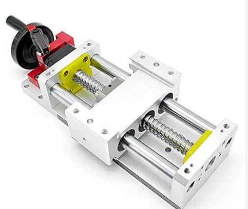
Ball Screws and Linear Guides Working in Harmony
Imagine trying to slide a heavy table across a room with perfect precision. Now imagine doing it thousands of times per day without deviation. That's the challenge ball screws and linear guides solve together.
Ball screws are the workhorses of linear motion. According to precision motion experts, a ball screw consists of a screw shaft, nut, steel balls, preload mechanism, reverser, and dustproof device. Its primary function is converting rotary motion into linear motion—or torque into axial force—with remarkable efficiency. The recirculating steel balls roll between the screw threads and nut, virtually eliminating the sliding friction that would cause rapid wear and positioning errors.
The ball screw bearing assembly at each end supports the rotating shaft while maintaining precise alignment. High-quality ball screw bearings use angular contact configurations that handle both radial and axial loads. When these bearings wear, you'll notice backlash increase and positioning accuracy degrade.
Linear guides (also called linear rails or slide rails) keep your axis moving along a perfectly straight path. Two main types dominate CNC applications:
- Profiled rail guides: These feature precision-ground raceways and recirculating ball or roller elements. They handle loads from multiple directions simultaneously—up, down, left, and right. Their low friction coefficients (roughly 1/50th that of sliding guides) enable smooth, precise movement.
- Round rail guides: Simpler and more economical, these work well for lighter loads and less demanding applications. However, they offer less rigidity and load capacity than profiled alternatives.
The interaction between these components creates what engineers call a closed-loop positioning system. The servo motor rotates, driving the ball screw. The screw converts that rotation into linear travel. The linear guides constrain that travel to a single axis with minimal deviation. Position encoders confirm the movement, closing the feedback loop.
In some machine configurations, a secondary gear or secondary gearbox sits between the servo motor and ball screw, providing speed reduction and torque multiplication. This arrangement helps smaller motors move heavier loads with greater precision.
Servo Systems - The Muscles Behind CNC Movement
Sounds complex? Think of servo systems as incredibly responsive muscles that follow orders with split-second precision. Every time your CNC controller sends a movement command, the servo system makes it happen.
The servo amplifier (often called a servo amp or servo drive) sits at the heart of this system. It receives low-power control signals from the CNC controller and amplifies them into the high-current pulses that drive the motor. Modern servo amplifiers incorporate sophisticated algorithms that optimize acceleration, deceleration, and positioning accuracy.
When a servo alarm triggers, it typically indicates overcurrent or overvoltage conditions. Most manufacturers print diagnostic LED codes directly on the servo amplifier housing, making initial troubleshooting straightforward. Common causes include jammed axes, shorted motor cables, or failed regenerative resistors.
The servo motor itself converts electrical energy into rotational force with extreme precision. Unlike standard motors that simply spin at full speed, servo motors can:
- Accelerate and decelerate with precise control
- Hold position against external forces
- Respond to position corrections within milliseconds
- Provide feedback on actual position versus commanded position
Encoders attached to servo motors send position data back to the controller, creating the closed-loop system that enables true precision machining. Route motor power cables separately from encoder cables to prevent electrical interference—loose shield grounds can cause phantom errors that frustrate even experienced technicians.
Proper thermal management keeps servo systems healthy. Many machines include a drive fan or dedicated cooling system to prevent amplifier overheating. When drives run hot, capacitor life decreases dramatically, leading to premature failure.
Signs of Motion System Wear and When to Act
Motion components don't fail without warning. Learning to recognize early symptoms lets you schedule repairs before catastrophic failure ruins a production run—or damages other expensive components.
Ball screw wear symptoms:
- Increasing backlash (play between clockwise and counterclockwise motion)
- Position drift that worsens throughout the workday as temperature rises
- Audible grinding or rough feel during slow axis movements
- Dimensional accuracy that degrades progressively over weeks or months
- Visible wear patterns or discoloration on screw threads
Ball screws require consistent lubrication. Clogged lube lines cause the screw to run dry, accelerating wear dramatically. Remove lines periodically, flush with clean solvent, and purge with fresh oil. Replace wipers every six months to keep chips out of the ball return circuit.
Linear guide failure symptoms:
- Lost preload causing excessive play in the carriage
- Rough or sticky movement, especially at slow feed rates
- Visible pitting or rust on rail surfaces
- Squealing sounds indicating inadequate lubrication
- Carriage rocking or tilting under load
Linear rails lose preload when ball recirculation channels wear or contamination enters the system. Unlike ball screws where you might adjust preload, worn linear guide blocks typically require complete replacement.
Servo system malfunction symptoms:
- Following errors (axis lags behind commanded position)
- Axis hunting or oscillation when holding position
- Sudden stops accompanied by alarm codes
- Excessive motor heating during normal operations
- Intermittent faults that correlate with specific axis positions
Following errors often indicate mechanical problems rather than electrical issues. When the axis lags beyond the controller's error limit, the drive faults to protect the machine. Check for dry ways, worn couplings, or insufficient servo gain before replacing expensive electronics.
After a motor or servo amplifier replacement, always run a step test and tune the drive parameters. A properly tuned system reaches commanded positions quickly, stops without oscillation, and holds position rock-steady.
Proactive maintenance beats reactive repairs every time. Track vibration data, monitor motor temperatures, and address small issues before they cascade into major failures. The motion control system demands attention, but rewards that attention with years of reliable, precise operation.
With motion systems translating commands into movement, the next critical question becomes: what actually removes material from your workpiece? That responsibility falls to the spindle—the true heart of any CNC machine's cutting capability.
Spindle Systems and Tool Interface Components
If motion control systems are the muscles of a CNC machine, the spindle is undoubtedly its beating heart. This rotating assembly holds your cutting tool and spins it at speeds ranging from a few hundred to tens of thousands of RPM. Every chip that flies, every surface that gleams, every dimension that hits tolerance—all depend on spindle performance.
Understanding spindle parts and configurations helps you match equipment to applications, troubleshoot performance issues, and protect what is often the most expensive single component in your machine. Whether you're machining aluminum at blistering speeds or grinding through hardened steel, spindle selection dramatically impacts your results.
Spindle Types and Their Ideal Applications
Not all spindles are created equal. Three primary drive configurations dominate CNC machining, each bringing distinct advantages to specific applications. Choosing wisely means understanding these tradeoffs.
Belt-driven spindles use a spindle pulley and belt system to transfer motor power to the spindle shaft. According to spindle specialists, this configuration offers several benefits: cost-effectiveness, reduced heat transfer from the separate motor, and high torque at low RPM—ideal for heavy cutting operations. The machining pulley arrangement also allows for speed ratio adjustments without replacing the entire drive system.
However, belt systems introduce vibration and noise that can affect surface finish quality. They're typically limited to lower maximum RPMs compared to other configurations, and belts wear over time requiring periodic replacement. You'll find belt-driven spindles excelling in general metalworking, woodworking applications handling large cutters, and prototyping environments where versatility matters more than ultimate precision.
Direct-drive spindles eliminate the gearbox pulley and belt entirely, connecting the motor shaft directly to the spindle shaft. This simplicity delivers significant advantages: reduced vibration for better accuracy, higher achievable speeds for smaller tools, and quick speed changes ideal for frequent tool changes.
The tradeoff? Lower torque at low RPM makes heavy cutting more challenging. Motor heat transfers directly to the spindle, often requiring liquid cooling systems. And the initial investment runs considerably higher than belt-driven alternatives. Direct-drive configurations shine in die and mold making, aerospace machining of aluminum and composites, and precision work for medical and electronics industries.
Motorized spindles (also called integral or built-in spindles) integrate the motor directly into the spindle housing. This compact design delivers superior performance: extremely high RPM capability, minimal vibration, and excellent precision. Space savings make them perfect for multi-axis machines where every inch matters.
These advantages come at a price—literally. Motorized spindles represent the most expensive option, and repairs often require replacing the entire unit rather than individual components. Advanced cooling systems become mandatory to maintain precision. You'll encounter motorized spindles in high-speed machining centers, precision grinding applications, and medical manufacturing creating intricate implants.
| Spindle Type | Typical RPM Range | Best Applications | Key Maintenance Considerations |
|---|---|---|---|
| Belt-Driven | 500 - 8,000 RPM | General metalworking, woodworking, prototyping | Belt tension checks, pulley alignment, belt replacement every 2,000-4,000 hours |
| Direct-Drive | 1,000 - 15,000 RPM | Die/mold making, aerospace aluminum, precision machining | Coolant system maintenance, coupling inspection, thermal monitoring |
| Motorized | 5,000 - 60,000+ RPM | High-speed machining, grinding, medical components | Advanced cooling system upkeep, vibration analysis, complete unit replacement when failed |
Understanding Spindle Specifications for Your Materials
Ever wonder why that new milling spindle seems perfect for aluminum but struggles with steel? The answer lies in understanding the relationship between RPM, power, and torque—and how different materials demand different spindle characteristics.
RPM range determines what cutting tools you can run effectively. Small diameter end mills require high spindle speeds to achieve optimal surface feet per minute. A 1/8" end mill cutting aluminum might need 20,000 RPM to reach proper cutting speed, while a 1" face mill in the same material runs efficiently at just 3,000 RPM.
Power rating (measured in horsepower or kilowatts) indicates how much material removal the spindle can sustain. High-speed spindles for aluminum might deliver 15-30 HP, while heavy-duty steel machining spindles often exceed 40 HP despite running at lower speeds.
Torque curves reveal the spindle's true character. Belt-driven and gear-driven spindles maintain high torque across a wide RPM range. Direct-drive spindles typically peak at higher speeds, making them less effective for heavy cuts at low RPM. Match your torque requirements to your typical cutting conditions.
A milling machine spindle faces unique challenges compared to lathe spindles. Milling operations impose significant side-loading forces as the cutter engages material tangentially. This demands bearings capable of handling radial loads without deflection—typically angular contact bearings in duplex or triplex configurations.
Key spindle parts that determine performance include:
- Bearings: Angular contact ceramic hybrid bearings offer the best combination of speed capability, load capacity, and longevity. Standard steel bearings work for moderate applications but limit maximum RPM.
- Drawbar mechanism: This spring-loaded or hydraulic system grips the tool holder securely. Drawbar force directly affects tool retention—insufficient force causes tool pullout during heavy cuts.
- Tool interface: Standards like BT (common in Japan and Asia), CAT (dominant in North America), and HSK (European origin, increasingly popular for high-speed work) determine tool holder compatibility. HSK tapers offer dual-contact design for superior rigidity at high speeds.
When selecting a spindle for your application, match material hardness to torque availability. Hard metals like steel and titanium need high torque at moderate speeds. Soft materials like aluminum and composites favor high-speed spindles that can achieve optimal surface footage with smaller tools.
Spindle Maintenance - Protecting Your Most Critical Component
Your spindle represents a significant investment—often $10,000 to $50,000 or more for precision units. Protecting that investment requires proactive monitoring and disciplined maintenance practices.
Temperature monitoring provides the earliest warning of bearing problems. Healthy spindles run at consistent temperatures during operation. A sudden increase—especially more than 10°F above normal operating temperature—signals bearing wear, inadequate lubrication, or cooling system problems. Many modern machines include built-in temperature sensors; use them.
Vibration analysis catches bearing defects before catastrophic failure. Characteristic vibration frequencies correspond to specific bearing components. A sudden spike at the ball pass frequency indicates developing bearing damage. Monthly vibration checks with a handheld analyzer can identify problems weeks before failure.
Bearing life expectations vary dramatically based on operating conditions. Manufacturers rate bearings in L10 life—the number of hours at which 10% of bearings will have failed. For high-speed spindles, expect 10,000-20,000 hours under ideal conditions. Contamination, overloading, or thermal abuse can reduce this dramatically.
Practical maintenance actions that extend spindle life:
- Warm up spindles gradually—especially in cold environments—before running at full speed
- Avoid side-loading tools during insertion or removal
- Keep tool holder tapers and spindle tapers meticulously clean
- Maintain proper coolant concentration to prevent rust on internal components
- Monitor and maintain air purge pressure that keeps contaminants out of the spindle housing
- Track run hours and schedule bearing replacement before predicted failure
A spindle running hot is a spindle crying for help. Never ignore temperature warnings—the cost of investigation is nothing compared to the cost of spindle replacement.
Understanding your spindle's capabilities and limitations positions you to get maximum value from this critical component. But even the best spindle needs direction—and that guidance comes from the control electronics and feedback systems that orchestrate every machine movement.
Control Electronics and Feedback Systems
You've got powerful spindles and precise motion systems—but what tells them exactly what to do and when? The answer lies in the control electronics: the sophisticated network of processors, interfaces, and sensors that transforms lines of G-code into perfectly machined parts. Without these components, your CNC machine would be like a race car without a driver.
Think of control electronics as the command center where digital instructions become physical reality. The controller interprets your program, the cnc machine panel lets you interact with the system, and feedback devices constantly verify that commanded movements match actual positions. Understanding these interconnected systems helps you troubleshoot faster, communicate with technicians more effectively, and recognize when something needs attention.
The CNC Controller - Your Machine's Brain
Every CNC machine revolves around its controller—a specialized computer designed specifically for coordinating multi-axis motion in real-time. Unlike your desktop PC that can pause to think, a CNC controller must process thousands of position calculations per second without hesitation. Even a momentary delay creates visible marks on your finished part.
How does this brain work? The controller reads your G-code program line by line, interpreting each command into specific instructions for motors, spindles, and auxiliary functions. It calculates the precise timing and velocity for each axis, ensuring smooth coordinated motion even when multiple axes move simultaneously along complex tool paths.
Major controller manufacturers like FANUC, Mitsubishi, and Siemens dominate the industry, each with distinct programming conventions and interface styles. According to precision equipment manufacturers, these controllers work seamlessly with high-performance feedback systems, accepting signals from various encoder protocols to maintain positioning accuracy.
Key controller functions include:
- Path interpolation: Calculating intermediate points between programmed positions for smooth continuous motion
- Velocity control: Managing acceleration and deceleration to prevent jerky movements
- Axis coordination: Synchronizing multiple motors to execute complex simultaneous movements
- Error monitoring: Continuously comparing commanded versus actual positions and triggering alarms when discrepancies exceed limits
- Compensation: Applying stored correction values for backlash, thermal expansion, and geometric errors
The control panel cnc operators interact with provides the human interface to this computational power. Modern panels typically include high-resolution displays showing program status, axis positions, spindle speed, and alarm conditions. Membrane keyboards or touchscreens allow program entry and parameter adjustment. Manual pulse generators (handwheels) let operators jog axes with tactile feedback—essential for setup operations and first-article verification.
When evaluating control systems, consider processing power, memory capacity, and connectivity options. Older controllers may struggle with complex programs containing thousands of short line segments. Modern systems handle these effortlessly while adding features like 3D toolpath visualization and network connectivity for program transfers.
Feedback Devices That Ensure Accuracy
Here's a critical concept that separates precision CNC machines from glorified power tools: closed-loop control. Without feedback, the controller assumes motors did exactly what they were told. With feedback, it knows exactly where axes actually moved—and corrects any discrepancies instantly.
A dc motor encoder or servo motor encoder mounts directly to the motor shaft, counting rotations with extreme precision. Rotary encoders typically generate thousands of pulses per revolution, allowing the controller to track position within fractions of a degree. When the motor rotates, pulse counts accumulate. The controller compares expected counts against actual counts, adjusting motor current to eliminate any following error.
For applications demanding the highest accuracy, linear encoders mount directly to machine axes, measuring actual slide position rather than inferring it from motor rotation. This eliminates errors from ball screw thermal expansion, coupling flexibility, and mechanical backlash. Premium machine tools like those produced by HEAKE incorporate Renishaw FORTiS enclosed linear encoders that provide direct position feedback with accuracies of 3-5 micrometers per meter.
A vector drive takes feedback integration even further, using encoder signals to precisely control motor torque and magnetic field orientation. This enables smooth motion at very low speeds and consistent torque regardless of motor velocity—essential for operations like thread cutting and rigid tapping.
Beyond position feedback, modern CNC machines incorporate sophisticated measurement devices:
A renishaw probe mounts in the spindle like a cutting tool, allowing automatic workpiece measurement during machining cycles. Touch the probe to a surface, and the controller records the exact position. This enables automatic work offset setting, in-process inspection, and adaptive machining that adjusts for actual part dimensions.
A renishaw tool setter performs similar magic for cutting tools. When a new tool loads into the spindle, it touches off against the setter, automatically determining exact tool length. This eliminates manual tool measurement and compensates for tool wear between operations. The combination of workpiece probing and tool setting enables truly unattended machining with consistent accuracy.
The synergy of using both FORTiS encoders and Renishaw's calibration products exceeds expectations—maximizing overall machine performance while significantly improving production efficiency.
Safety Components Every Operator Should Understand
CNC machines pack serious power into compact spaces. Spindles spinning at thousands of RPM, axes accelerating at multiple G's, and cutting forces that can shatter tools in milliseconds—all create genuine hazards. Safety components prevent accidents by monitoring machine status and forcing safe conditions when problems occur.
Every operator should understand these essential safety components:
- Emergency stop buttons: Large red mushroom-head switches positioned within easy reach that immediately halt all machine motion and spindle rotation when pressed. E-stops use normally-closed contacts, so a wiring failure defaults to the safe stopped condition.
- Limit switches: Positioned at the ends of each axis travel, these sensors prevent overtravel that could damage the machine. Hard limits trigger immediate stops; soft limits in the controller prevent programming errors from commanding impossible positions.
- Homing sensors: These establish machine zero position during startup. The controller moves each axis until it triggers the home switch, establishing a known reference point for all subsequent positioning.
- Door interlocks: Switches that detect when enclosure doors open, typically pausing or preventing spindle operation to protect operators from flying chips and rotating tools.
- Spindle orientation sensors: Confirm the spindle has stopped and oriented correctly before allowing tool changes—preventing tool changer crashes.
- Hydraulic and pneumatic pressure switches: Monitor clamping pressure on chucks, fixtures, and tool holders. Low pressure triggers alarms before workpieces or tools can fly loose.
- Thermal sensors: Monitor spindle, motor, and drive temperatures, forcing shutdowns before overheating causes permanent damage.
When diagnosing control system problems, start with the basics. Check for alarm codes on the display—modern controllers provide specific error messages pointing toward the cause. Verify all safety circuits are satisfied: doors closed, E-stops released, pressure switches showing adequate levels. Many frustrating "control problems" trace back to a limit switch knocked out of alignment or a door interlock needing adjustment.
For intermittent issues, examine cable connections carefully. Control cables carry low-voltage signals susceptible to interference from motor power cables routed too closely. Shield connections at both ends of encoder cables prevent phantom position errors. Corrosion on connector pins—especially in high-humidity environments—causes mysterious faults that come and go.
The control system ties everything together: interpreting your intent, commanding motion, verifying results, and protecting people and equipment. With this command infrastructure understood, the next logical question becomes: how do you hold the tools and workpieces that actually create your parts?
Tool Holding and Workholding Essentials
You've got a precision spindle spinning at thousands of RPM and motion systems accurate to thousandths of an inch. But here's the thing—none of that matters if your cutting tool wobbles in its holder or your workpiece shifts mid-cut. Tool holding and workholding systems form the critical interface between machine capability and actual machining results.
Think about it this way: even a perfectly programmed tool path produces scrap if the workpiece moves during cutting. And a premium carbide end mill delivers disappointing performance when excessive runout causes uneven chip loads. These clamping systems might seem unglamorous compared to servo drives and controllers, but they directly determine whether your parts hit tolerance or miss entirely.
Chucks, Collets, and Tool Holders Explained
When we define chucks in CNC applications, we're talking about workholding devices that grip cylindrical or irregular-shaped parts during turning operations. Chucks come in several configurations, each suited to specific needs.
3-jaw chucks offer self-centering convenience—all three jaws move simultaneously when you tighten the chuck. This makes them ideal for round stock and hexagonal materials where quick setups matter. However, the self-centering mechanism introduces some runout, typically 0.002" to 0.005" depending on chuck quality and wear.
4-jaw independent chucks allow individual jaw adjustment, enabling precise centering of irregular shapes and off-center work. Skilled operators can dial in runout below 0.0005" with patience. The tradeoff? Setup takes considerably longer since each jaw requires separate adjustment.
Collet chucks deliver superior precision for round workpieces. According to tooling specialists, collets encircle the cutting tool shank or workpiece to evenly distribute holding power around its center bore. The tapered design enables collets to achieve concentricity far exceeding drill chucks and side-lock holders.
Three popular collet systems dominate CNC applications:
- ER collets: The most versatile option, offering 0.020" to 0.040" collapse range per collet. This flexibility means fewer collets cover a wider range of shank sizes. ER collets also accommodate coolant-through tools and quick-change modifications.
- TG collets: Deliver greater holding power than ER collets due to their 4° taper versus ER's 8° taper. However, larger collet nuts can interfere with pocket milling operations, and the narrow collapse range means one collet fits only one shank size.
- DA collets: An older design still found in many shops. Their four-slot configuration can cause two clamping faces to disengage at certain collapse ranges, potentially causing deflection under cutting loads.
Tool holders bridge the gap between spindle taper and cutting tool. Quality indicators for tooling include runout specifications (premium holders achieve under 0.0001" TIR), balance grades (G2.5 or better for high-speed applications), and material quality affecting heat treatment and wear resistance.
Remember that collets are designed as wear components—the softest element in the tool holding system. Industry recommendations suggest replacing collets every 4-6 months depending on usage. Signs of worn collets include bell-mouthing at the face, fretting marks appearing as rust-colored spots, and increased tool deflection under cutting loads.
Workholding Solutions for Different Applications
Securing your workpiece demands just as much attention as holding your cutting tools. The right workholding solution depends on part geometry, material properties, production volume, and required precision. According to CNC workholding experts, proper workholding ensures higher precision, reduced tool wear, and safer operations.
| Workholding Method | Advantages | Limitations | Typical Applications |
|---|---|---|---|
| Vise | Quick setup, high clamping force, versatile jaw options, excellent repeatability | Limited to rectangular stock, part size constrained by jaw opening, potential jaw marks | Milling and drilling on small to medium prismatic parts |
| Custom Fixture | Optimized for specific parts, superior accuracy, enables multiple operations per setup | High initial cost, long lead time to create, inflexible for design changes | Production runs of complex or unique geometries |
| Vacuum Table | No clamp interference, holds thin materials flat, quick loading/unloading | Limited to flat parts, requires sealed surfaces, cannot hold porous materials | Sheet materials, plastics, composites, thin sheet metal |
| Magnetic Chuck | Instant clamping, full top surface access, no part distortion | Ferrous materials only, limited holding force for interrupted cuts, requires flat bottom surface | Grinding operations, light milling on steel and iron parts |
Soft jaws deserve special mention for their versatility. These custom-machined aluminum or plastic jaws mount in standard vises or chucks, shaped to match specific part profiles. They prevent marring delicate surfaces while providing positive location for repeatability. Many shops machine soft jaws right on the CNC machine that will use them, ensuring perfect alignment.
For high-production environments, tombstones and angle plates maximize spindle utilization by presenting multiple parts or multiple sides simultaneously. A four-sided tombstone can hold 20 or more parts, dramatically reducing load/unload time relative to cutting time.
Gear parts and other components requiring rotational indexing often use dedicated fixtures incorporating replacement gears or a pinion gear shaft mechanism for precise angular positioning. These specialized setups enable operations like gear tooth machining or radial hole patterns without repositioning the workpiece.
Tool Changers and Magazine Systems
Modern CNC machines rarely use just one cutting tool. Automatic tool changers (ATCs) swap tools in seconds, enabling complex parts requiring multiple operations to run without operator intervention. Understanding these systems helps you maximize unattended production time.
Carousel-style magazines arrange tools in a circular pattern, rotating to bring the desired tool to the exchange position. Capacities typically range from 16 to 40 tools. The carousel rotates bidirectionally, finding the shortest path to each tool. Simple, reliable, and cost-effective—but tool capacity limits complex jobs.
Chain-type magazines store tools along a linked chain that travels in a loop. This design enables larger capacities (60 to 120+ tools) while maintaining reasonable change times. The chain moves continuously in one direction to the selected position.
Matrix or rack-style magazines store tools in grid patterns, often behind protective doors. A dedicated arm retrieves and replaces tools. These systems offer the highest capacities but typically have longer change times.
The tool management ecosystem extends beyond just storage:
- Tool presetters: Offline devices that measure tool length and diameter before installation. Operators load measured data directly to the controller, eliminating on-machine touch-offs that consume spindle time.
- Tool life management: Controller functions that track cutting time per tool, automatically swapping to backup tools when programmed limits are reached.
- Gearbox parts within tool changers require periodic lubrication and inspection. Worn drive mechanisms cause unreliable tool changes and potential crashes.
Quality evaluation for tool changing systems focuses on repeatability—how consistently does each tool seat in the spindle? Premium systems achieve tool-to-tool repeatability under 0.0002". Watch for signs of wear including inconsistent tool lengths after changes, hesitation during carousel rotation, or increased change cycle times.
A tool holding system is only as good as its weakest component. Premium spindles paired with worn collets or sloppy tool changers deliver disappointing results.
Proper workholding and tool holding form the foundation for everything else your CNC machine does. With parts secured and tools gripped correctly, the stage is set for productive machining. But even the best setups need support from auxiliary systems that keep operations running smoothly hour after hour.
Auxiliary Systems That Support Continuous Operation
Picture a CNC machine running through the night, producing part after part without human intervention. What keeps it going? While spindles and motion systems get the glory, auxiliary systems quietly handle the unglamorous work that makes unattended operation possible. Coolant washes away heat and chips. Lubricants reduce friction on precision surfaces. Hydraulic and pneumatic circuits power clamping mechanisms. Without these support systems, even the finest CNC machines parts would grind to a halt within hours.
Understanding auxiliary systems transforms how you approach machine maintenance. These components often provide the earliest warning signs of developing problems—long before expensive damage occurs to primary systems.
Coolant Systems - More Than Just Keeping Things Cool
Coolant does far more than its name suggests. Yes, it removes heat from the cutting zone—but it also lubricates the tool-workpiece interface, flushes chips away from the cut, and can even improve surface finish quality. A properly functioning cnc coolant filtration system protects your investment in cutting tools while ensuring consistent part quality.
How does coolant impact tool life? During cutting, temperatures at the tool tip can exceed 1,000°F. Without cooling, carbide tools soften and wear rapidly. High-pressure coolant delivery—increasingly common in modern machines—directs fluid precisely at the cutting zone, dramatically extending tool life in demanding materials like stainless steel and titanium.
The filtration component deserves special attention. Contaminated coolant carries fine metal particles that scratch workpiece surfaces and accelerate pump wear. Premium cnc coolant filtration systems use paper or fabric media to remove particles down to 10-20 microns. Some systems add magnetic separators for ferrous fines and coalescers that remove tramp oil contamination.
Common coolant system failures include:
- Biological contamination: Bacteria and fungus thrive in coolant sumps, producing foul odors and health hazards. Regular concentration testing and biocide treatment prevent outbreaks.
- Tramp oil accumulation: Way lube and hydraulic leaks float on coolant surfaces, reducing cooling efficiency and promoting bacterial growth. Skimmers remove this contamination continuously.
- Pump cavitation: Low coolant levels or clogged suction screens cause pumps to run dry, destroying seals and impellers. Maintain proper levels and clean intake screens weekly.
- Nozzle blockages: Chips and debris clog coolant delivery nozzles, reducing flow to cutting zones. Inspect and clear nozzles during tool changes.
Vector fans mounted in electrical cabinets work alongside coolant systems to manage machine temperatures. These vector fan units prevent drive overheating that can cause nuisance shutdowns during extended cutting cycles.
Lubrication and Its Impact on Machine Longevity
Every sliding surface, every rotating bearing, every ball screw thread depends on proper lubrication. When oil flow stops—even briefly—metal contacts metal directly. The resulting wear accelerates geometrical degradation, eventually compromising the precision your CNC machine was designed to deliver.
CNC machines typically use two distinct lubrication circuits:
Way lube systems deliver metered amounts of oil to linear guide rails and ball screws through an oil tube network. These automatic lubricators pulse small quantities at timed intervals, maintaining protective films without creating messy excess. The lubricant must resist being washed away by coolant while providing adequate boundary protection under heavy loads.
Spindle lubrication demands different properties entirely. High-speed spindle bearings require oil-air or oil-mist systems that deliver microscopic quantities precisely where needed. Too much lubricant causes churning and heat buildup; too little allows bearing surfaces to contact directly. Premium spindles include flow sensors that trigger alarms if lubrication delivery fails.
Lubrication starvation—the most common failure mode—rarely announces itself dramatically. Instead, you'll notice gradually increasing axis friction, unusual sounds during rapid movements, or slow deterioration of positioning accuracy. By the time obvious symptoms appear, significant wear has already occurred.
Preventive actions that protect against lubrication failures:
- Check oil reservoir levels daily—most systems include sight glasses or level switches
- Verify lube pump operation by observing cycle indicator lights
- Inspect each oil tube distribution point monthly for blockages
- Change filters according to manufacturer schedules, typically every 3-6 months
- Use only manufacturer-specified lubricant grades—viscosity matters
Hydraulic and Pneumatic Support Systems
Many CNC operations require clamping forces that exceed what manual or electric systems can provide. Hydraulic circuits deliver tremendous force for chuck clamping, fixture actuation, and tailstock positioning. Pneumatic systems handle lighter duties: tool changing, door actuation, and chip blow-off.
Hydraulic systems pack significant power into compact packages. A small power unit pressurizes oil to 1,000-3,000 PSI, delivering that force through precision valves to cylinders throughout the machine. When hydraulic cylinder repair parts wear—seals, wipers, and piston rings—pressure drops and clamping force diminishes. Hyd cylinder repair kits typically include all soft components needed to restore cylinder function.
Signs of hydraulic system problems include:
- Slow cylinder actuation indicating worn pump or internal leakage
- Visible oil leaks at fittings, cylinders, or valve blocks
- Excessive power unit cycling suggesting internal bypassing
- Foamy or milky oil indicating water contamination
- Elevated oil temperature from worn pump or restricted cooling
When ordering hydraulic cylinder repair parts or hyd cyl repair kits, match specifications exactly—bore diameter, rod diameter, and seal materials must match original equipment for proper function.
Pneumatic systems present different maintenance challenges. Compressed air contains moisture that condenses in lines and corrodes components. Air dryers and water separators protect downstream equipment, but require regular service. Lubricators add oil mist to protect sliding components in valves and cylinders.
Both systems share a critical vulnerability: contamination. Particles in hydraulic oil score precision valve surfaces. Water in pneumatic lines freezes in cold conditions and corrodes aluminum components. Filtration and conditioning represent your first line of defense.
Auxiliary System Maintenance Checklist
Consistent maintenance prevents most auxiliary system failures. The following schedule covers essential inspection points:
-
Daily Inspections:
- Coolant level and concentration (refractometer test)
- Way lube reservoir level
- Hydraulic oil level
- Air pressure gauge readings
- Chip conveyor operation
-
Weekly Inspections:
- Coolant sump for tramp oil and odors
- Lube pump cycling and delivery verification
- Air filter/water separator draining
- Hydraulic filter condition indicators
- Coolant nozzle condition and alignment
-
Monthly Inspections:
- Oil tube distribution point verification
- Coolant filter replacement or cleaning
- Hydraulic hose condition inspection
- Pneumatic cylinder seal inspection
- Chip conveyor belt or hinge condition
-
Quarterly Inspections:
- Complete coolant change or treatment
- Hydraulic fluid analysis
- Spindle lubrication system verification
- Pneumatic regulator calibration
- Deep clean of coolant tank and chip pans
Chip conveyors deserve mention as critical enablers of unattended operation. These mechanical systems—whether belt, screw, or hinge-type—continuously remove chips from the work zone. A jammed conveyor quickly buries the cutting area in swarf, causing tool breakage and workpiece damage. Listen for unusual sounds and watch for chip buildup that indicates developing problems.
Auxiliary systems rarely fail without warning. The question is whether you're paying attention to the early signs.
With auxiliary systems maintaining the environment for precision machining, the final piece of the puzzle becomes keeping everything running optimally over time. Proactive maintenance strategies transform occasional equipment users into true machine masters—the subject of our next discussion.
Maintenance Strategies for CNC Machine Components
Here's a truth that separates thriving machine shops from struggling ones: the best CNC machines parts in the world deliver disappointing results without consistent maintenance. That precision spindle loses accuracy when bearings run dry. Those expensive linear guides develop play when contamination invades their raceways. Your investment in quality equipment only pays off when supported by disciplined care.
Think of maintenance as insurance for your production capability. A few minutes of daily attention prevents hours of unplanned downtime. Catching wear early means scheduling cnc repair during planned windows rather than scrambling for emergency cnc machine repair services when deadlines loom. The shops that master maintenance don't just save money—they deliver consistent quality that wins repeat customers.
Daily, Weekly, and Monthly Maintenance Routines
Effective maintenance follows a structured rhythm. Daily checks catch immediate problems before they cause damage. Weekly inspections identify developing issues while solutions remain simple. Monthly services address wear items before failure occurs. This layered approach maximizes uptime while minimizing both maintenance costs and unexpected breakdowns.
The following maintenance schedule matrix organizes essential tasks by component category and frequency:
| Component Category | Daily Checks | Weekly Inspections | Monthly Services | Annual Overhaul Items |
|---|---|---|---|---|
| Structural Components | Visual inspection for damage, wipe down surfaces | Check leveling, inspect way covers for damage | Clean under way covers, inspect for rust | Precision leveling verification, geometric accuracy check |
| Motion Systems | Listen for unusual sounds during rapid moves | Verify lube delivery to ball screws/guides, check for play | Measure backlash, inspect wipers and seals | Ball screw preload adjustment, linear guide replacement evaluation |
| Spindle Assembly | Monitor temperature, listen for bearing noise | Check taper cleanliness, verify drawbar function | Vibration analysis, coolant system inspection | Bearing replacement assessment, runout verification |
| Control Electronics | Verify no active alarms, check display function | Inspect cable connections, clean cooling filters | Backup parameters, verify encoder function | Battery replacement, complete system backup, firmware review |
| Tool/Workholding | Inspect tool holders for damage, clean tapers | Check chuck jaw condition, verify clamping force | Measure collet runout, inspect soft jaws | Chuck rebuild, tool changer alignment verification |
| Auxiliary Systems | Check fluid levels, verify conveyor operation | Test coolant concentration, drain air separators | Change filters, clean coolant tank | Complete coolant system flush, hydraulic fluid replacement |
Start each day with a quick walk-around inspection. Check fluid levels in coolant sumps, way lube reservoirs, and hydraulic tanks. Listen as axes move during warm-up—healthy machines sound smooth while developing problems often announce themselves through grinding, squealing, or clicking. This five-minute investment catches problems while solutions remain simple.
Weekly inspections dig deeper. Run each axis through its full travel, feeling for rough spots or unusual resistance. Verify that automatic lubricators cycle properly by watching indicator lights and checking delivery points for fresh oil. Inspect chip conveyors and coolant nozzles for blockages that could compromise cutting performance.
Monthly services address components that accumulate wear gradually. Measure ball screw backlash with a dial indicator—increasing values signal developing wear. Clean or replace coolant filters before contamination reaches cutting zones. Document all measurements to track trends over time.
Recognizing Wear Before It Becomes Failure
Your CNC machine constantly communicates its condition—if you know how to listen. Dimensional drift, surface finish degradation, and unusual sounds each point toward specific components needing attention. Learning to interpret these signals lets you schedule repairs proactively rather than reacting to catastrophic failures.
Dimensional drift symptoms and likely causes:
- Consistent offset in one direction: Ball screw thermal expansion—check for inadequate warm-up or cooling system problems
- Increasing error throughout the day: Thermal growth in spindle or structure—verify coolant temperature and consider warm-up routines
- Random position errors: Encoder problems, loose coupling, or intermittent electrical connections
- Progressive accuracy loss over weeks: Ball screw or linear guide wear—measure backlash and inspect for visible damage
- Errors that change with axis position: Lead screw pitch error or damaged ball screw section—map error across full travel
Surface finish problems and their sources:
- Chatter marks at consistent frequency: Spindle bearing wear, insufficient rigidity, or improper cutting parameters
- Random scratches or gouges: Chip recutting, tool breakage, or contaminated coolant carrying abrasive particles
- Waviness patterns: Servo tuning issues, mechanical resonance, or worn linear guides
- Spiral marks on turned surfaces: Chuck runout, spindle bearing play, or workpiece deflection
Unusual sounds demand immediate investigation:
- High-pitched whine during spindle operation: Bearing preload loss or lubrication starvation—stop immediately to prevent catastrophic failure
- Grinding during axis movement: Contamination in linear guides or ball screw, failed wiper seals
- Clicking or popping: Loose coupling, worn ball return tube, or broken recirculating balls
- Squealing during rapid moves: Dry ways, inadequate lubrication, or binding from misalignment
When troubleshooting, isolate variables systematically. If dimensional errors appear suddenly, consider what changed recently—new tooling, different material, temperature swings, or recent maintenance. Gradual degradation points toward wear mechanisms. Document symptoms carefully; this information proves invaluable when consulting with cnc machine repair service technicians.
When to Repair vs. When to Replace Components
Every worn component presents a decision: repair cnc parts in place, rebuild them, or source cnc replacement parts entirely. The right choice balances immediate costs against long-term reliability and production requirements.
Factors favoring repair:
- Minor wear that adjustment can compensate (ball screw preload, bearing clearance)
- Localized damage that doesn't affect overall function
- Long lead times for replacement parts that would extend downtime
- Historical reliability after previous repairs
- Components nearing end of machine life where investment doesn't make sense
Factors favoring replacement:
- Wear exceeding adjustment range (backlash beyond specification)
- Repeated failures after repair attempts
- Safety-critical components (spindle bearings, brake systems)
- Obsolete parts where repairs require custom fabrication
- Total repair cost approaching replacement cost
For critical machines, consider searching for "cnc repair near me" to identify local service providers who can respond quickly to urgent needs. Established relationships with qualified technicians pay dividends when unexpected failures occur. Many manufacturers also offer factory haas service programs and similar support options that provide access to genuine parts and trained technicians.
Some components warrant proactive replacement before failure:
- Spindle bearings: Replace based on running hours rather than waiting for symptoms—typically every 15,000-25,000 hours depending on application severity
- Ball screw wipers and seals: Replace every 6-12 months regardless of apparent condition
- Way lube filters: Change on schedule, not when clogged—restricted filters starve critical surfaces
- Backup batteries: Replace annually to prevent parameter loss that could require expensive reprogramming
- Coolant: Change completely every 6-12 months even with proper maintenance—contamination accumulates over time
The cheapest repair is the one you never need. Investing in preventive maintenance costs a fraction of emergency repairs and lost production.
Document everything. Maintenance logs tracking fluid changes, measurements, and repairs create valuable history for troubleshooting future problems. This documentation also supports warranty claims and helps when evaluating equipment for resale or replacement.
Maintenance excellence doesn't happen accidentally—it requires systems, schedules, and commitment. But shops that master these disciplines enjoy higher uptime, better part quality, and lower total cost of ownership. With your maintenance strategy established, the final consideration becomes sourcing quality cnc replacement parts and finding manufacturing partners who share your commitment to precision.
Sourcing Quality CNC Parts and Manufacturing Partners
You've invested time understanding every critical component—from structural frames to auxiliary systems. But here's where that knowledge becomes truly powerful: when you're sourcing precision cnc components or evaluating manufacturing partners. Whether you need haas spare parts for maintenance, haas replacement parts for upgrades, or custom cnc machining parts for production, knowing what separates excellent suppliers from mediocre ones protects your investment and your production schedules.
Think about it this way: a manufacturing partner isn't just someone who makes parts to print. According to automotive industry specialists, the right partner collaborates from the earliest stages, supports prototypes and pre-production phases, validates designs for manufacturability, and proactively mitigates quality and delivery risks before series production even starts. That level of engagement transforms a transactional supplier relationship into a strategic advantage.
Quality Certifications That Matter in CNC Manufacturing
When evaluating potential suppliers for cnc parts, certifications provide your first objective filter. These aren't just plaques on the wall—they represent audited systems, documented processes, and accountability that directly impact the quality of components you receive.
IATF 16949 stands as the gold standard for automotive manufacturing. This certification goes beyond basic ISO 9001 requirements, demanding specific controls for production part approval, statistical process monitoring, and continuous improvement methodologies. If your cnc milling parts end up in vehicles, working with IATF 16949-certified suppliers significantly reduces quality risks.
ISO 9001 establishes fundamental quality management system requirements. While less rigorous than IATF 16949, this certification confirms that a supplier has documented processes, tracks quality metrics, and follows structured approaches to customer requirements.
AS9100D applies specifically to aerospace applications, adding requirements for configuration management, risk assessment, and supply chain controls beyond standard ISO 9001. Aerospace cnc parts demand this level of traceability.
Beyond certifications, investigate the actual quality control methods in use. Industry guidance recommends asking about inspection tools—pin gauges, micrometers, coordinate measuring machines (CMMs)—and requesting sample inspection reports. Statistical Process Control (SPC) implementation demonstrates that a supplier actively monitors process capability rather than just inspecting finished parts.
Proper QC documentation is crucial for regulated industries like aerospace or automotive. Certifications indicate structured processes and repeatable quality.
Evaluating Manufacturing Partners for Your Components
Certifications open the door, but deeper evaluation reveals whether a partner truly fits your needs. Here's what to look for when vetting potential suppliers for haas parts, precision cnc components, or production machining services:
- Certified quality management systems: IATF 16949 for automotive, AS9100D for aerospace, or ISO 9001 as a baseline—verified through current certification documents
- Statistical Process Control implementation: Active SPC monitoring demonstrates commitment to process stability, not just final inspection
- Design for Manufacturability (DfM) feedback: Partners who review your drawings and suggest improvements save you money and prevent production problems
- Technical communication capability: Can they discuss tolerances, stress points, and material performance—not just timelines and pricing?
- Integrated capabilities: Suppliers offering CNC machining, assembly, surface treatments, and metrology under one roof minimize logistics complexity
- Transparent pricing structure: Detailed cost breakdowns showing machine time, material, labor, setup, and tooling indicate honest partnerships
- Lead time reliability: Ask about typical lead times, rush order capabilities, and how they handle workflow disruptions
- Scalable capacity: Tooling flexibility, batch volume planning, and pre-series support matter for growing programs
According to manufacturing partnership experts, experienced suppliers anticipate problems before they arise. Judge their ability to understand technical drawings, provide DfM feedback, and suggest machining alternatives. Responsive, clear communication ensures you won't be left in the dark when issues arise.
When assessing equipment capabilities, look for advanced CNC lathes, milling machines, grinders, and coordinate measuring machines. The technical team should demonstrate proficiency with CAD/CAM tools and multi-axis machining. For cnc milling parts requiring complex geometries, five-axis capability often proves essential.
Scaling from Prototype to Production
Here's where many engineering projects stumble: a prototype looks perfect, but production parts don't match. The gap between making one excellent part and making ten thousand consistent parts requires different capabilities, different quality systems, and different partner mindsets.
Understanding this spectrum helps you choose partners appropriately:
Prototype stage (1-10 pieces): Speed and flexibility matter most. You need fast turnaround to validate designs, with partners willing to work from preliminary drawings. However, smart prototyping validates the production process, not just the part design. Partners who use production-representative methods during prototyping save you from costly surprises later.
Low-volume production (10-500 pieces): This transition phase industrializes the process. According to manufacturing experts, this is where you perfect the recipe to make parts 10,000 times. Fixturing becomes standardized. Inspection methods get documented. Process parameters get locked down. Partners who excel here prevent the quality fade that often appears when scaling volume.
Full production (500+ pieces): Execution becomes paramount. With engineering work complete, focus shifts to consistency, on-time delivery, and cost optimization. Partners need capacity buffers, scheduling discipline, and robust quality systems that catch variation before it ships.
The most valuable partners support this entire journey. They engage during prototyping to identify manufacturability issues early—when changes cost little. They document everything during low-volume validation, creating the foundation for consistent production. And they have the capacity and systems to scale without quality degradation.
Lead time considerations vary dramatically across this spectrum. Prototype parts might ship in days. Production runs require planning weeks or months ahead. Partners with flexible setups can accommodate last-minute design changes or volume shifts without compromising quality—a capability worth premium pricing.
Component quality directly affects your downstream manufacturing. Precision cnc components that arrive out of tolerance create assembly problems, rework costs, and delivery delays. Partners who understand your end application—not just the drawing dimensions—can flag potential issues before they cascade through your production.
Shaoyi Metal Technology exemplifies these manufacturing partner qualities for automotive applications. Their IATF 16949 certification confirms automotive-grade quality systems. Statistical Process Control implementation ensures process stability across production runs. With lead times as fast as one working day for urgent needs, they support the rapid iteration that prototype development demands while maintaining the consistency that production requires.
Their capability spanning from rapid prototyping to mass production addresses the full journey discussed above. Whether you need complex chassis assemblies requiring multi-axis machining or custom metal bushings demanding tight tolerances, integrated capabilities under one roof simplify your supply chain. For automotive cnc machining needs, explore their services at https://www.shao-yi.com/auto-machining-parts/.
Ultimately, sourcing quality cnc parts and selecting manufacturing partners requires the same attention to detail you'd apply to evaluating machine components themselves. Certifications provide baseline assurance. Technical capability determines what's achievable. Communication quality predicts partnership success. And the ability to scale from prototype through production protects your program from the costly disruptions that plague poorly-chosen supplier relationships.
The knowledge you've gained about CNC machines parts—from structural foundations to auxiliary systems—now becomes your competitive advantage. You can evaluate suppliers' technical claims, ask informed questions about quality systems, and recognize when quoted capabilities match your actual requirements. That expertise transforms you from a passive buyer into an engaged partner, driving better outcomes for your projects and your organization.
Frequently Asked Questions About CNC Machine Parts
1. What are the 7 major parts of a CNC machine?
The seven major CNC machine parts include the Machine Control Unit (MCU) that interprets G-code, input devices for program loading, the drive system with servo motors and ball screws, machine tools including the spindle assembly, the feedback system with encoders for precision, the bed and table providing structural foundation, and the cooling system that manages heat during cutting operations. Each component works together to transform digital commands into precise machined parts.
2. What are CNC machine parts?
CNC machine parts encompass all components that enable computer-controlled machining operations. These include structural elements like cast iron beds and frames, motion control systems featuring ball screws and linear guides, spindle assemblies for material removal, control electronics including controllers and encoders, tool holding devices like chucks and collets, and auxiliary systems such as coolant filtration and lubrication circuits. Understanding these parts helps operators maintain equipment and troubleshoot issues effectively.
3. How much does it cost to get a part CNC machined?
CNC machining costs typically range from $50 to $150 per hour depending on equipment complexity and precision requirements. Setup fees start at $50 and can exceed $1,000 for complex jobs. Total project costs depend on material type, part geometry, tolerances, quantity, and finishing requirements. Working with IATF 16949-certified manufacturers like Shaoyi Metal Technology can provide competitive pricing with quality assurance for automotive and precision components.
4. How often should CNC machine parts be maintained?
CNC machines require daily checks of fluid levels and unusual sounds, weekly inspections of lubrication delivery and axis movements, monthly measurements of backlash and filter replacements, and annual overhauls including geometric accuracy verification and bearing assessments. Spindle bearings typically need replacement every 15,000-25,000 hours, while ball screw wipers should be changed every 6-12 months regardless of condition to prevent costly failures.
5. What certifications should I look for in a CNC parts supplier?
For automotive applications, IATF 16949 certification is essential as it ensures automotive-grade quality systems with statistical process control. ISO 9001 provides baseline quality management verification, while AS9100D applies to aerospace components requiring enhanced traceability. Beyond certifications, evaluate suppliers for SPC implementation, CMM inspection capabilities, Design for Manufacturability feedback, and scalable capacity from prototyping through mass production.