 Small batches, high standards. Our rapid prototyping service makes validation faster and easier —

CNC Custom Parts Decoded: From Material Choice To Final Inspection
Understanding CNC Custom Parts and Their Manufacturing Foundation
When you need a component that doesn't exist in any catalog, you're entering the world of CNC custom parts. These are precision-engineered components manufactured to your exact specifications using computer numerical control technology. Unlike grabbing a standard bolt from a hardware store shelf, custom parts are built from scratch based on your unique design requirements.
CNC custom parts are components specifically designed and manufactured to meet unique application requirements, produced using computer-controlled machining processes that remove material from solid blocks to create tailored solutions matching exact customer specifications.
What Makes a Part Custom in CNC Manufacturing
So what separates custom CNC parts from their off-the-shelf counterparts? It comes down to three fundamental differences:
- Tailored geometry: Every dimension, angle, and feature is designed specifically for your application rather than conforming to standardized sizes
- Material flexibility: You choose the exact material grade that matches your performance needs, from specific aluminum alloys to specialty plastics
- Unique specifications: Tolerances, surface finishes, and functional requirements are defined by your project rather than generic manufacturing standards
Imagine you're developing a new medical device. Standard components simply won't fit the unique internal housing your design requires. That's when precision CNC machining becomes essential. The same applies across aerospace, automotive, and industrial equipment sectors where performance demands exceed what mass-produced parts can deliver.
The Role of Computer Control in Precision Fabrication
CNC fabrication relies on digital instructions to guide cutting tools with remarkable accuracy. The process starts with a CAD (Computer-Aided Design) model that contains every dimension and tolerance your part needs. This digital blueprint then translates into machine instructions through CAM (Computer-Aided Manufacturing) software.
During machining, the CNC machine follows programmed tool paths with precision often reaching ±0.001 inches or tighter. The computer controls spindle speeds, cutting depths, and movement sequences, removing human variability from the equation. This consistency means your first part matches your hundredth part with near-identical accuracy.
What makes this approach powerful for custom work? Flexibility. If testing reveals your prototype needs modification, updating the CAD model and producing a revised version takes hours rather than weeks. You're not locked into expensive tooling or rigid production setups that traditional manufacturing methods require.
Whether you need a single prototype or a small production run, CNC parts offer the precision and customization that standard components simply cannot match. Understanding this foundation prepares you to make informed decisions as you navigate material selection, tolerance specifications, and manufacturing partner evaluation in the sections ahead.
CNC Machining Processes Explained for Custom Part Production
Choosing the right machining process can make or break your custom part project. Each CNC operation offers distinct advantages depending on your part geometry, material, and precision requirements. Understanding these differences helps you communicate effectively with manufacturing partners and optimize your designs for production.
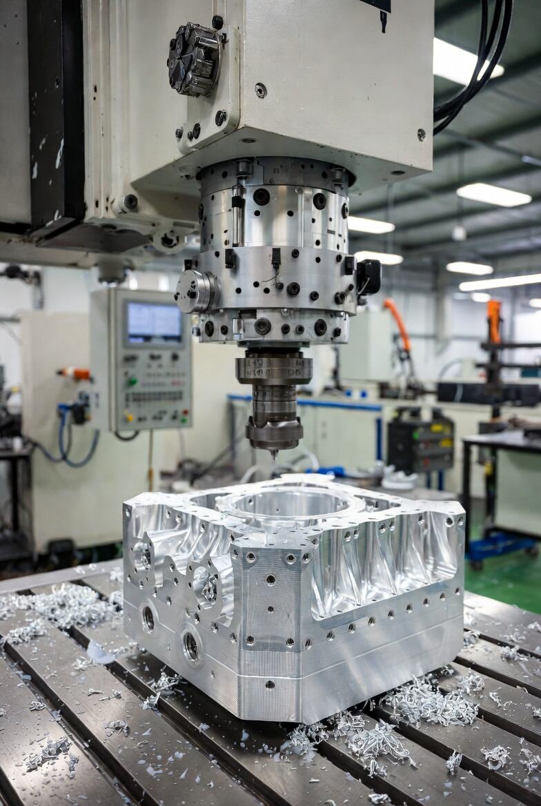
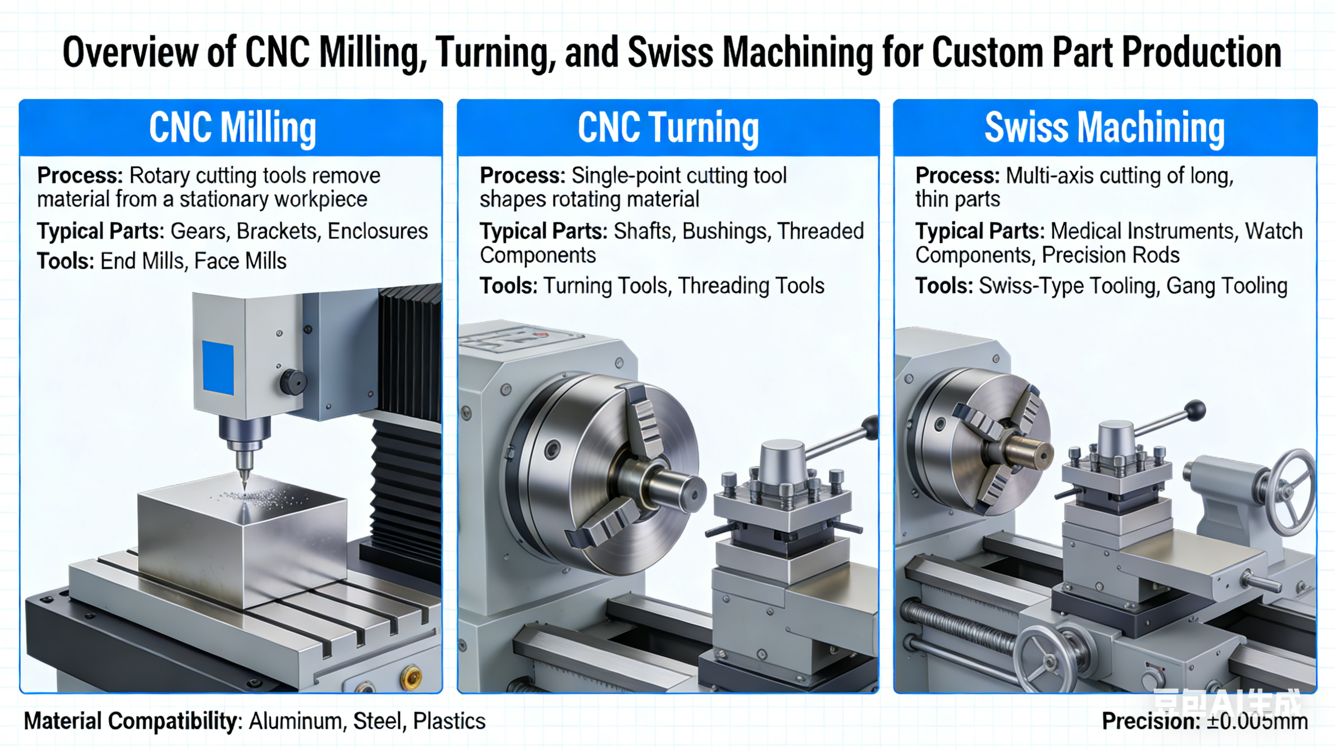
CNC Milling for Complex Geometries and Surface Features
When your part requires intricate shapes, pockets, or detailed surface features, CNC machining milling is typically your best option. In this process, a rotating cutting tool moves across a stationary workpiece, removing material layer by layer to create your desired geometry.
CNC milling parts excel in several scenarios:
- Complex 3D contours: Irregular surfaces, organic shapes, and multi-faceted geometries that would be impossible to turn
- Flat surfaces and precise pockets: Enclosures, mounting plates, and housings requiring square corners and flat bottoms
- Multi-feature components: Parts needing holes, slots, threads, and surface details machined from multiple angles
The real power of milling becomes apparent with 5 axis CNC machining services. Unlike standard 3-axis machines that move along X, Y, and Z directions only, 5-axis centers add two rotational axes. This allows the cutting tool to approach your workpiece from virtually any angle without repositioning.
Why does this matter for your custom parts? Single-setup machining eliminates cumulative tolerances that occur when you reposition a part between operations. Complex aerospace components, turbine blades, and medical implants with organic geometries benefit significantly from this capability. You'll also notice improved surface finishes since the tool can maintain optimal cutting angles throughout complex contours.
CNC Turning for Cylindrical and Rotational Components
Need shafts, bushings, pins, or any component with rotational symmetry? CNC turning is your go-to process. Here, the workpiece rotates while a stationary cutting tool shapes the material, making it ideal for cylindrical geometries.
CNC turning services excel at producing:
- Shafts and axles: Components requiring precise diameters and concentricity
- Bushings and sleeves: Parts with critical inner and outer diameter relationships
- Threaded components: External and internal threads machined with high accuracy
- Flanges and rings: Symmetrical parts with stepped diameters
CNC turning parts typically achieve excellent surface finishes on cylindrical surfaces, often eliminating secondary finishing operations. The process is also highly efficient for production volumes since cycle times for rotational components are generally shorter than milling equivalent geometries.
Modern CNC turning centers often include live tooling capabilities, meaning the machine can perform milling operations while the part is still chucked. This hybrid approach reduces handling and maintains tight tolerances between turned and CNC milled features on the same component.
Swiss Machining for High-Precision Small Components
When your project involves small-diameter parts requiring exceptional precision, Swiss machining deserves serious consideration. Originally developed for Swiss watchmaking, this specialized turning process uses a sliding headstock and guide bushing that supports the workpiece extremely close to the cutting zone.
This design difference delivers remarkable advantages:
- Tolerances as tight as ±0.0002 inches: The guide bushing minimizes deflection and vibration that plague conventional lathes on small parts
- Superior surface finishes: Reduced chatter produces smoother surfaces without secondary operations
- Complex small parts in one setup: Multi-axis movement and live tooling handle turning, milling, drilling, and threading simultaneously
Industries like medical device manufacturing, electronics, and aerospace rely heavily on Swiss machining for components like bone screws, electrical connectors, and precision pins. If your custom part has a diameter under 1.25 inches and requires tight tolerances with intricate features, Swiss-type lathes often deliver the best combination of precision and efficiency.
Process Selection Guide
Matching your part requirements to the right process prevents costly mistakes and unnecessary delays. This comparison table provides quick reference guidance:
| Process Type | Best Applications | Typical Tolerances | Ideal Part Geometries |
|---|---|---|---|
| 3-Axis CNC Milling | Flat surfaces, simple pockets, basic 3D shapes | ±0.002" to ±0.005" | Prismatic parts, plates, simple enclosures |
| 5-Axis CNC Milling | Complex contours, aerospace components, impellers | ±0.001" to ±0.003" | Organic shapes, undercuts, multi-angle features |
| CNC Turning | Shafts, bushings, threaded parts, flanges | ±0.001" to ±0.005" | Cylindrical and rotationally symmetric parts |
| Swiss Machining | Medical screws, electrical pins, watch components | ±0.0002" to ±0.001" | Small-diameter parts under 1.25" with complex features |
| Mill-Turn Centers | Parts requiring both turning and milling features | ±0.001" to ±0.003" | Hybrid geometries, reduced setup requirements |
Consider your part's dominant geometry first. Cylindrical? Start with turning. Complex prismatic with multiple angles? Milling makes sense. Small with tight tolerances? Explore Swiss machining. Many custom parts benefit from combining processes, and experienced manufacturing partners can recommend the optimal approach based on your specific requirements.
With your process options clarified, the next critical decision involves selecting the right material. Your choice directly impacts machinability, final part performance, and overall project cost.
Material Selection Guide for CNC Custom Parts
Your material choice fundamentally shapes everything about your custom part, from how it performs under stress to what it costs to manufacture. Selecting the wrong material leads to premature failures, excessive machining costs, or parts that simply don't meet application requirements. Getting it right requires understanding how different CNC machining materials behave during cutting operations and in real-world service conditions.
Aluminum Alloys for Lightweight Custom Components
Aluminum dominates CNC aluminum applications for good reason. With an excellent strength-to-weight ratio, natural corrosion resistance, and outstanding machinability, aluminum alloys often represent the most economical choice for custom parts. But not all aluminum is created equal.
The comparison between 6061 and 7075 aluminum illustrates how alloy selection impacts your project:
| Property | Aluminum 6061-T6 | Aluminum 7075-T6 | Practical Implication |
|---|---|---|---|
| Tensile Strength | 310 MPa | 570 MPa | 7075 handles nearly 84% more pulling force before failure |
| Yield Strength | 270 MPa | 490 MPa | 7075 resists permanent deformation under 81% higher loads |
| Hardness (Brinell) | 95 BHN | 150 BHN | 7075 offers 58% better scratch and wear resistance |
| Corrosion Resistance | Excellent | Moderate | 6061 performs better in harsh or marine environments |
| Machinability | Excellent | Good | 6061 machines faster with less tool wear, reducing costs |
| Relative Cost | Lower | 20-35% higher | 6061 offers better value for moderate-strength applications |
When should you choose each alloy? Consider 6061 aluminum for general structural components, transportation parts, marine applications, and consumer goods where moderate strength meets your requirements. Its superior machinability translates directly to lower production costs and faster turnaround times.
Reserve 7075 aluminum for applications demanding exceptional strength-to-weight performance. Aircraft structures, high-performance sporting equipment, and military applications justify the premium cost. Just remember that 7075's higher copper content makes it more susceptible to corrosion, so protective coatings or anodizing become important considerations.
Steel and Bronze Selection for Demanding Applications
When aluminum machining won't deliver the strength, hardness, or wear resistance your application demands, steel and bronze alloys step in.
Stainless Steel Options: For parts requiring high strength combined with corrosion resistance, stainless steel 304 serves as the workhorse alloy. It handles most environmental conditions and corrosive media while maintaining excellent mechanical properties. Need better performance in saltwater or chemical exposure? Stainless 316 delivers enhanced corrosion resistance at a modest cost increase.
Mild and Alloy Steels: General-purpose applications like jigs, fixtures, and structural components often use mild steel 1018 for its good machinability and weldability. When higher strength and wear resistance matter, alloy steel 4140 provides improved hardness and fatigue resistance suitable for demanding industrial applications.
Bronze Applications: Machining bronze becomes essential when you need exceptional wear resistance and low-friction performance. CNC bronze parts excel in bearings, bushings, gears, and valve components where metal-to-metal contact occurs.
The most common bronze cnc applications use these alloys:
- C932 Bearing Bronze: Outstanding wear resistance and anti-friction properties make it ideal for bushings, thrust washers, and gears operating under heavy loads
- C954 Aluminum Bronze: Superior strength and excellent saltwater corrosion resistance suit marine components, pump shafts, and heavy-duty bearings
- C510 Phosphor Bronze: Excellent fatigue resistance and elasticity make it perfect for springs, electrical contacts, and fasteners requiring flexibility under repeated stress
Engineering Plastics for Specialized Requirements
Metal isn't always the answer. Engineering plastics offer unique advantages including lightweight construction, electrical insulation, chemical resistance, and lower machining costs for certain applications.
Delrin material (technically POM or polyoxymethylene) stands out as the most machinable plastic available. When your design requires high precision, excellent dimensional stability, low friction, and minimal water absorption, Delrin delivers. You'll find it in precision gears, bearings, and components requiring tight tolerances that would be costly to achieve in metal.
Machining nylon makes sense when you need good impact strength, chemical resistance, and moderate wear performance at lower cost than Delrin. Nylon 6 and nylon 66 are the most common grades, appearing in bushings, wear pads, and structural components where some moisture absorption is acceptable.
Other notable plastic options include:
- Polycarbonate: Exceptional impact strength and optical clarity for protective covers and transparent components
- Acrylic: Excellent optical properties for display cases, light guides, and aesthetic applications
- PEEK: Premium performance with excellent mechanical properties and chemical resistance, often replacing metal in demanding aerospace and medical applications
Comprehensive Material Comparison
This reference table summarizes the most common CNC machining materials to help narrow your selection:
| Material | Key Properties | Common Applications | Machinability Rating |
|---|---|---|---|
| Aluminum 6061 | Good strength, excellent corrosion resistance, lightweight | Structural components, automotive parts, marine hardware | Excellent |
| Aluminum 7075 | High strength, good fatigue resistance, moderate corrosion resistance | Aerospace structures, high-performance equipment, military parts | Good |
| Stainless Steel 304 | High strength, excellent corrosion resistance, good ductility | Food processing, medical devices, architectural components | Moderate |
| Stainless Steel 316 | Superior corrosion resistance, good strength, chemical resistant | Marine hardware, chemical processing, pharmaceutical equipment | Moderate |
| Mild Steel 1018 | Good weldability, excellent toughness, cost-effective | Jigs, fixtures, general structural parts | Excellent |
| C932 Bronze | Outstanding wear resistance, anti-friction, high load capacity | Bearings, bushings, gears, valve components | Good |
| C954 Aluminum Bronze | High strength, excellent saltwater corrosion resistance | Marine components, pump shafts, heavy-duty bearings | Moderate |
| Delrin (POM) | High precision, low friction, excellent dimensional stability | Precision gears, bearings, insulators, fluid handling | Excellent |
| Nylon 6/66 | Good impact strength, chemical resistance, moderate wear resistance | Bushings, wear pads, structural plastic components | Good |
| PEEK | Premium strength, chemical resistance, high temperature capability | Aerospace components, medical implants, semiconductor parts | Moderate |
Your material selection should balance performance requirements against manufacturing costs. Higher-strength materials often require slower cutting speeds, specialized tooling, and more machine time, all factors that increase your per-part cost. When moderate properties meet your needs, choosing easier-to-machine materials like 6061 aluminum or Delrin keeps production efficient and budgets manageable.
Once you've identified your material, the next consideration becomes equally critical: what tolerances does your application actually require, and how do those specifications affect both manufacturing complexity and final part cost?
Precision Tolerances and Surface Finish Standards
What does ±0.005 inches actually mean for your project? Tolerances define the permissible limits of variation in your part's dimensions, and understanding them prevents two costly mistakes: over-specifying precision you don't need (driving up costs) or under-specifying requirements that compromise functionality (causing assembly failures or premature wear).
According to ISO manufacturing standards, no process produces geometrically perfect parts. Tolerances communicate acceptable deviations from nominal specifications, ensuring your precision cnc machining parts function as intended within their mechanical context.
Tolerance Classes and Their Real-World Implications
Not every dimension on your part demands the same precision. International standards like ISO 2768 and ISO 286 provide frameworks that simplify tolerance specification while ensuring parts meet functional requirements.
ISO 2768 General Tolerances apply by default to dimensions without specific callouts on your drawings. These tolerances cover linear dimensions, angular measurements, external radii, and chamfer heights. Most CNC machine shops work to ISO 2768-medium as their standard, which typically satisfies general-purpose applications.
Here's what common tolerance classes mean in practice:
- Standard tolerances (±0.005" to ±0.010"): Suitable for general structural components, enclosures, and non-mating features where exact fit isn't critical
- Medium tolerances (±0.002" to ±0.005"): Appropriate for most precision machining parts including mating components with clearance fits and functional assemblies
- Tight tolerances (±0.001" to ±0.002"): Required for interference fits, precision bearings, and components where minimal clearance affects performance
- Ultra-precision tolerances (±0.0005" or tighter): Reserved for optical systems, aerospace instrumentation, and medical devices where micron-level accuracy is essential
For features requiring specific tolerances beyond general ISO 2768 standards, ISO 286 provides detailed tolerance grades (IT6, IT7, IT8) particularly useful for fits between mating parts. When you specify a shaft diameter of 50mm at ISO 286 Grade IT6, you're allowing only ±19 micrometers of deviation, a precision machining service that ensures reliable assembly with corresponding holes.
When Tight Tolerances Are Worth the Investment
Tighter tolerances always cost more. According to manufacturing research, the cost increase stems from several compounding factors:
- Slower machining speeds: Achieving finer finishes and tighter dimensions requires reduced feed rates and cutting speeds
- More frequent tool changes: Worn tools drift out of tolerance faster when specifications are tighter
- Additional inspection time: Verifying precision dimensions requires CMM measurements or other sophisticated metrology
- Higher scrap rates: Parts falling outside tight specifications get rejected more frequently
- Climate-controlled environments: Ultra-precision work may require temperature-stable machining conditions
So when do tight tolerances justify their premium? Consider these scenarios where precision cnc machining services deliver essential value:
- Rotating assemblies: Shaft-to-bearing interfaces where excessive clearance causes vibration, noise, and premature wear
- Sealing surfaces: Components requiring leak-free performance under pressure or vacuum conditions
- Precision instruments: Optical mounts, measurement devices, and calibration equipment where accuracy determines function
- Safety-critical applications: Aerospace, medical, and automotive components where dimensional variation could cause failures
The strategic approach? Apply tight tolerances only to critical-to-function features while allowing general tolerances elsewhere. This targeted specification controls costs without compromising performance where it matters.
Surface Finish Standards and Selection Criteria
Surface roughness describes the microscopic texture left after machining, quantified most commonly using Ra (average roughness) values measured in micrometers. Lower Ra numbers indicate smoother surfaces. According to surface roughness research, this parameter affects not just appearance but also friction, wear resistance, fatigue life, and sealing capability.
Most precision machining services offer four standard surface roughness levels:
| Ra Value | Surface Characteristics | Best Applications | Cost Impact |
|---|---|---|---|
| 3.2 µm Ra | Visible machine marks, standard commercial finish | General structural parts, enclosures, non-contact surfaces | Baseline (no premium) |
| 1.6 µm Ra | Faint cut marks visible, smooth to touch | Tight fits, light load-bearing surfaces, slow-moving parts | +2.5% cost increase |
| 0.8 µm Ra | High-grade finish, minimal visible texture | Stress-concentrated areas, vibrating components, bearing surfaces | +5% cost increase |
| 0.4 µm Ra | Very smooth, no observable cut marks | High-speed rotating parts, precision seals, optical components | +15% cost increase |
How do you choose the right finish? Match surface roughness to functional requirements:
- Friction and wear: Lower Ra values reduce friction coefficients and improve wear resistance for sliding or rotating contact surfaces
- Fatigue life: Smoother surfaces eliminate stress concentrators where cracks initiate under cyclic loading
- Sealing performance: O-ring grooves and gasket surfaces need smooth finishes (typically 1.6 µm Ra or better) for reliable sealing
- Aesthetic appearance: Decorative parts and consumer-facing components benefit from finishes of 0.8 µm Ra or smoother
- Coating adhesion: Some coatings bond better to slightly textured surfaces rather than ultra-smooth finishes
Avoid the common mistake of specifying smooth finishes everywhere. A 3.2 µm Ra finish works perfectly for most non-critical surfaces, and requesting unnecessary smoothness simply adds cost without functional benefit.
With tolerances and surface finish requirements defined, your next step involves optimizing your design for manufacturability. Smart design decisions made early prevent costly revisions later and help your CNC manufacturing partner deliver parts efficiently.
Design for Manufacturing Principles in CNC Production
Your CAD model might look perfect on screen, but will it machine efficiently? Design for Manufacturing (DFM) principles bridge the gap between engineering intent and shop floor reality. When you apply these guidelines early, your CNC machining parts become easier to produce, faster to deliver, and less expensive to manufacture.
According to DFM analysis research, many RFQs stall because parts that look perfect in CAD reveal geometric conflicts, tolerance issues, or material problems once machining starts. Understanding DFM helps you avoid these costly surprises before submitting your design for quoting.
Designing Features for Optimal Machinability
Every feature on your custom machined parts affects how quickly and accurately a CNC machine can produce them. Sounds complex? It doesn't have to be. Focus on these key areas where smart design choices make the biggest impact:
Internal Corner Radii: CNC milling tools are cylindrical, which means they naturally leave rounded internal corners. Specifying sharp 90-degree internal corners forces manufacturers to use progressively smaller tools with multiple slow passes, dramatically increasing cycle time.
- Specify corner radii at least one-third of the cavity depth
- Use consistent radii throughout your part to minimize tool changes
- For a 12mm deep pocket, a 5mm or larger corner radius allows efficient machining with standard tooling
Wall Thickness: Thin walls vibrate during cutting, causing chatter marks, dimensional inaccuracy, and potential part failure. Thicker sections machine more stably and reduce the risk of scrapped parts.
- Maintain minimum 0.8mm wall thickness for metal machined parts
- Keep plastic walls at 1.5mm or thicker to prevent deflection
- Avoid abrupt thickness transitions that create stress concentrations
Pocket and Cavity Depth: Deep pockets require long cutting tools that deflect under cutting forces, compromising accuracy and surface finish. The deeper you go, the slower and more expensive machining becomes.
- Limit cavity depth to four times the feature's largest dimension in the XY plane
- For standard tooling, keep depth-to-width ratios under 4:1
- Deeper cuts may require 5-axis machining or EDM, significantly increasing costs
Undercuts and Inaccessible Features: Standard CNC machine parts can only reach features accessible from above. Undercuts, internal channels, and hidden geometries often require special tooling, multiple setups, or alternative processes entirely.
- Eliminate non-functional undercuts wherever possible
- Consider splitting complex parts into assemblies that machine from one direction each
- When undercuts are essential, add relief cuts or specify T-slot cutters that can reach them
Common Design Mistakes That Increase Production Costs
Even experienced engineers make design choices that unnecessarily inflate CNC machining part costs. Recognizing these patterns helps you catch problems before they reach the quote stage.
Over-Tightening Tolerances: Applying ±0.01mm tolerances to every dimension contradicts good DFM practice. Tight tolerances require slower feeds, more inspection time, and higher rejection rates. According to machining cost research, tighter tolerances should apply only to functional features while non-critical dimensions use standard ±0.125mm or better tolerances.
Forcing Monolithic Designs: Sometimes engineers try cramming everything into a single machined block when an assembly would be simpler, cheaper, and faster to produce. Deep internal channels, complex undercuts, and multi-directional features often machine more efficiently as separate components bolted or welded together.
Ignoring Standard Sizes: Non-standard hole diameters require end mills instead of drill bits, adding machining time. Thread specifications outside common standards need special taps. Whenever possible, specify standard fractional or metric sizes that match readily available tooling.
Excessive Surface Finish Requirements: Specifying mirror finishes everywhere adds polishing time without functional benefit. Apply strict surface finish requirements only to sealing surfaces, bearing interfaces, and aesthetic areas while leaving general surfaces at standard as-machined finishes.
DFM Best Practices Checklist
Before submitting your design for quoting, verify these manufacturability factors:
- Geometry: All internal corners have appropriate radii; no sharp edges requiring micro-tooling
- Wall thickness: Minimum 0.8mm for metals, 1.5mm for plastics throughout the part
- Pocket depth: Depth-to-width ratios under 4:1 for standard tooling access
- Tolerances: Tight tolerances applied only to functional features; general tolerances elsewhere
- Undercuts: Eliminated where non-functional; relief features added where required
- Hole sizes: Standard drill diameters specified; thread callouts match common standards
- Part orientation: Design allows machining in minimum setups, ideally one or two
- Surface finish: Requirements matched to function, not over-specified globally
File Formats and Drawing Requirements for Accurate Quotes
According to CNC drawing guidelines, incomplete documentation is the most common reason RFQs stall. Preparing complete, consistent files accelerates quoting and reduces back-and-forth clarification requests.
Required 3D Files: Submit STEP (.step or .stp) files as your primary 3D format since they're universally accepted across CAM systems. IGES files work as alternatives, but avoid native CAD formats that may require specific software versions to open correctly.
2D Technical Drawings: Your PDF drawings should include:
- Complete GD&T (Geometric Dimensioning and Tolerancing) callouts for critical features
- All thread specifications including size, pitch, and depth
- Surface finish requirements with Ra values where applicable
- Material specification including grade, temper, and any certification requirements
- Clear reference datums for inspection purposes
- Revision history and current revision level
Avoiding Common Documentation Errors: Ensure your 3D model and 2D drawing match exactly. Conflicting dimensions between files force suppliers to pause and request clarification. Verify all units are consistent (millimeters or inches, not mixed), all views are complete, and no tolerance callouts contradict each other.
Well-prepared documentation signals professionalism and engineering competence. Suppliers respond faster and more accurately when they have everything needed to evaluate your cnc machining part without guessing at your intent.
With your design optimized for manufacturability and documentation complete, how does CNC machining compare against alternative production methods? Understanding when CNC offers advantages over 3D printing, injection molding, or casting helps you select the right process for your specific application.
CNC Machining Compared to Alternative Manufacturing Methods
Should you machine your custom part or print it? What about injection molding for larger quantities? Choosing the right manufacturing method affects everything from your per-part cost to how quickly you can iterate on designs. Each process excels in specific scenarios, and understanding these distinctions helps you make strategic decisions rather than defaulting to familiar options.
According to Hubs manufacturing research, CNC machining and 3D printing often overlap in use cases, particularly for prototypes and functional end-use parts. The key is matching your specific requirements to the process that delivers the best combination of cost, quality, and speed.
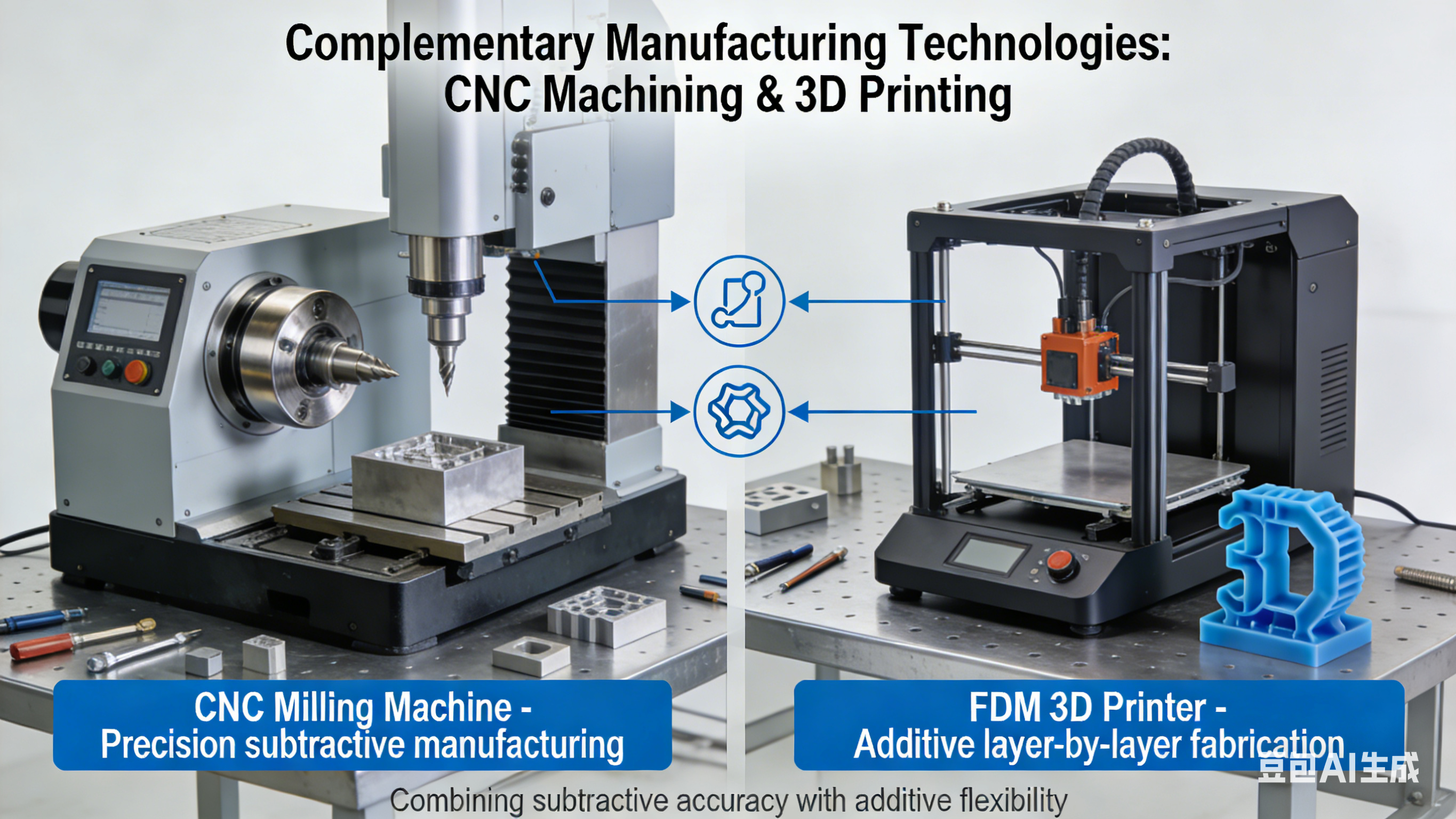
CNC Versus 3D Printing for Custom Part Production
CNC machining and 3D printing represent fundamentally opposite approaches. CNC removes material from solid blocks (subtractive manufacturing), while 3D printing builds parts layer by layer (additive manufacturing). This core difference drives their respective strengths.
When CNC Machining Wins:
- Superior dimensional accuracy: CNC delivers tight tolerances and excellent repeatability across all three axes, making it the better choice when precision is critical
- Consistent mechanical properties: Machined parts exhibit fully isotropic strength since they're cut from solid material blocks rather than built in layers
- Surface finish quality: CNC produces smoother surfaces directly off the machine, often eliminating secondary finishing operations
- Material selection: Machining handles a broader range of production-grade metals and engineering plastics with predictable properties
When 3D Printing Makes Sense:
- Complex geometries: Parts with internal lattice structures, organic shapes, or topology-optimized features that would be impossible to machine
- Rapid turnaround: Need parts fast? 3D printing can deliver prototypes within 24 hours without tooling setup
- Lower cost for small volumes: Additive manufacturing typically costs less than CNC for quantities under 10 units
- Specialty materials: Flexible TPU, high-performance metal superalloys, and composite materials often suit 3D printing better
Here's a practical guideline: if your part can be easily produced using subtractive methods, CNC machining often delivers better results. However, 3D printing's design freedom becomes invaluable when your geometry simply cannot be machined, regardless of cost.
When to Choose CNC Over Injection Molding
Injection molding produces plastic parts by forcing molten material into metal molds. It's incredibly efficient at scale but carries significant upfront investment. According to manufacturing cost research, steel molds cost $5,000 to $100,000, making injection molding a gamble when your design might change.
CNC prototyping advantages over injection molding:
- Zero tooling costs: You pay per hour of machine time rather than investing in expensive molds upfront
- Design flexibility: Modify your CAD file and produce updated parts immediately without scrapping tooling
- Lead time: CNC delivers parts in 2-5 days while mold creation takes minimum 3 weeks
- Material variety: CNC handles aluminum, titanium, steel, and engineering plastics that injection molding cannot process
The crossover point matters. For quantities under 500 identical plastic parts, CNC prototype machining typically wins on total project cost. Once you exceed 1,000+ units with a stable design, injection molding's per-part economics become compelling. Between 500 and 1,000 units, the decision depends on material requirements, complexity, and whether further design changes are likely.
Understanding Casting and When It Applies
Casting pours molten material into molds to create near-net-shape parts, offering advantages for certain applications that neither CNC nor 3D printing match well.
Consider casting when:
- You need complex internal cavities that would require extensive machining
- Your volumes justify mold investment but injection molding materials won't work
- Large parts would waste excessive material if machined from solid blocks
- Specialty alloys like aluminum bronzes or specific steel grades suit your application
Many projects use hybrid approaches, casting near-net-shape blanks and then CNC machining critical features to final tolerances. This combination captures casting's material efficiency while achieving the precision only machining delivers.
Manufacturing Method Selection Guide
This comparison table summarizes when each method excels:
| Method | Best Volume Range | Material Options | Precision Level | Lead Time |
|---|---|---|---|---|
| CNC Machining | 1-500 parts (metals); 1-1,000 parts (plastics) | All metals, engineering plastics, composites | Excellent (±0.001" achievable) | 2-5 days typical |
| 3D Printing (FDM/SLS) | 1-50 parts | Limited plastics, some metals via DMLS | Good (±0.005" typical) | 1-3 days typical |
| Injection Molding | 1,000+ parts | Thermoplastics, limited thermosets | Good (±0.002-0.005") | 3-8 weeks (includes tooling) |
| Casting | 100-10,000 parts | Aluminum, bronze, steel, iron alloys | Moderate (±0.010" typical) | 4-12 weeks (includes tooling) |
| Vacuum Casting | 10-50 parts | Polyurethane resins mimicking production plastics | Good (±0.005") | 1-2 weeks |
Rapid CNC Prototyping Applications
Prototype machining services bridge the gap between concept and production more effectively than many engineers realize. While 3D printing dominates rapid prototyping conversations, CNC prototype parts offer distinct advantages during development.
When rapid cnc prototyping outperforms alternatives:
- Functional testing: CNC parts survive stress tests that would destroy printed prototypes, providing realistic performance data
- Production-representative materials: Testing with actual aluminum, steel, or engineering plastics reveals issues that prototype materials might mask
- Tight tolerance validation: Verifying fits and clearances requires the precision only machining delivers
- Surface finish evaluation: Assessing cosmetic quality or coating adhesion needs machined surfaces, not layer lines
According to rapid prototyping research, the most successful development programs use multiple methods strategically. Start with 3D printed models for early form and fit checks where speed matters most. Transition to cnc prototype machining when functional validation requires production-grade materials and precision. This staged approach optimizes both cost and development speed.
Carbon fiber prototyping represents a special case where method selection becomes particularly important. Carbon fiber composite parts can be 3D printed using chopped fiber filaments for quick concept validation, but functional prototypes typically require CNC machining of layup panels to achieve the strength properties production parts will exhibit.
The strategic takeaway? Don't default to a single manufacturing method. Match your process selection to each phase of development, your volume requirements, and your precision needs. Prototype machining services, 3D printing, and molding each serve specific purposes, and the best projects leverage multiple approaches as designs mature.
With your manufacturing method selected, understanding what drives CNC custom parts pricing helps you prepare accurate project budgets and communicate effectively with potential suppliers.
Cost Factors and Pricing Considerations for Custom Parts
Why does one CNC quote come in at $50 per part while another shows $200 for seemingly similar work? Understanding what drives cnc machining price helps you budget accurately, communicate effectively with suppliers, and identify opportunities to reduce costs without sacrificing quality.
According to manufacturing cost research, CNC machining costs combine machine time, material expenses, setup charges, and labor. However, the relative impact of each factor shifts dramatically based on your specific part requirements and order quantities.
Key Factors That Determine Your CNC Part Pricing
Not all cost drivers carry equal weight. Here's what affects your bottom line, ranked by typical impact on total project cost:
- Material selection and cost: Raw material prices fluctuate with market conditions, and machinist metal cost varies significantly between grades. Titanium and specialty stainless steels cost far more than aluminum 6061, both in material price and machining time required
- Part complexity and geometry: Deep pockets, thin walls, undercuts, and multi-axis features require specialized tooling, longer cycle times, and more sophisticated machines. Simple prismatic parts machine faster than organic 3D contours
- Tolerance requirements: Tighter specifications demand slower feeds, more frequent tool changes, and additional inspection time. Moving from ±0.005" to ±0.001" can double machining time on critical features
- Machine type required: A standard 3-axis mill runs at lower hourly rates than 5-axis centers or Swiss-type lathes. Complex geometries requiring advanced equipment carry premium pricing
- Setup and programming time: First-article production includes CAM programming, fixture design, and machine setup. These fixed costs spread across your order quantity
- Surface finish and post-processing: Requirements beyond as-machined finishes add operations. Anodizing, bead blasting, chemical film applications, and precision polishing each contribute to total cost
- CNC cutting tool consumption: Hard materials like titanium and hardened steel accelerate tool wear. Small cnc machining with micro-tools also increases tooling costs per part
How Quantity Affects Per-Unit Manufacturing Costs
Economies of scale work powerfully in CNC production, but the relationship isn't linear. Understanding the cost curve helps you optimize order quantities.
| Production Volume | Cost Characteristics | Strategic Considerations |
|---|---|---|
| 1-10 parts (Prototypes) | Highest per-unit cost; setup and programming dominate | Focus on design validation; accept premium pricing for flexibility |
| 11-100 parts (Low volume) | Setup costs spread across more units; significant per-part reduction | Batch similar parts together; standardize tooling where possible |
| 101-500 parts (Medium volume) | Material bulk pricing kicks in; process optimization justified | Invest in fixture improvements; negotiate material pricing |
| 500+ parts (Production) | Automation options become viable; lowest per-unit costs | Consider dedicated tooling; explore lights-out machining |
The steepest cost reduction occurs between single prototypes and initial production batches. According to machining economics research, ordering 10 parts instead of 1 might reduce per-unit cost by 40-60% since setup time distributes across more pieces.
Getting Accurate Quotes: What Information to Prepare
Incomplete quote requests delay your project and often result in inflated estimates when suppliers add contingency for unknowns. According to quoting best practices, preparing comprehensive documentation accelerates the cnc quote online process and yields more competitive pricing.
Before requesting quotes, gather these essentials:
- 3D CAD files: STEP format preferred for universal compatibility across CAM systems
- 2D technical drawings: Include all critical dimensions, GD&T callouts, thread specifications, and surface finish requirements
- Material specification: Exact grade, temper, and any certification requirements (e.g., mill certifications for aerospace)
- Quantity needed: Specify prototype quantities separately from production volumes for appropriate pricing tiers
- Tolerance requirements: Identify which features require tight tolerances versus general specifications
- Surface finish needs: Specify Ra values for critical surfaces and identify any post-processing requirements
- Target delivery date: Rush orders cost more; providing realistic timelines enables standard pricing
- Special requirements: Certifications, inspection documentation, or industry-specific compliance needs
When using online machining quotes platforms, upload complete documentation rather than relying on instant pricing algorithms alone. Automated systems estimate based on geometry and material, but nuanced requirements often need human review for accurate pricing.
Lead Time Factors That Affect Your Project Schedule
Lead time and cost interconnect directly. Understanding what drives delivery schedules helps you plan projects realistically and avoid expensive rush charges.
- Current shop capacity: Busy periods extend lead times; planning ahead secures better scheduling
- Material availability: Standard aluminum ships immediately while exotic alloys may require weeks for procurement
- Complexity and setup requirements: Multi-setup parts and complex fixturing add days to production schedules
- Inspection and quality documentation: First-article inspection reports and certification packages require additional time
- Post-processing operations: Heat treatment, anodizing, plating, and other finishing operations add to total lead time
Standard lead times for CNC custom parts typically range from 5-15 business days depending on complexity. Expedited services can compress this to 1-3 days at premium pricing, sometimes 25-50% above standard rates.
With cost factors understood, how do you verify that finished parts actually meet your specifications? Quality assurance processes and industry certifications provide the answer, ensuring your investment delivers components that perform as intended.
Quality Assurance and Certification Standards
Your CNC custom parts might look perfect, but how do you know they'll perform as intended? Quality assurance transforms manufacturing from guesswork into science, using systematic inspection methods and documented processes to verify every dimension, surface, and material property meets your specifications.
According to CNC quality control research, the primary objective of quality control is to minimize errors by accurately identifying and addressing potential issues before defective parts reach customers. Without rigorous inspection, dimensional inaccuracies, surface finish defects, and material inconsistencies can result in significant financial losses and damaged industry reputation.
Quality Control Methods for Precision Components
Effective inspection of precision cnc machined parts involves multiple verification methods, each suited to different measurement challenges. Here's what precision machining companies use to ensure your components meet specifications:
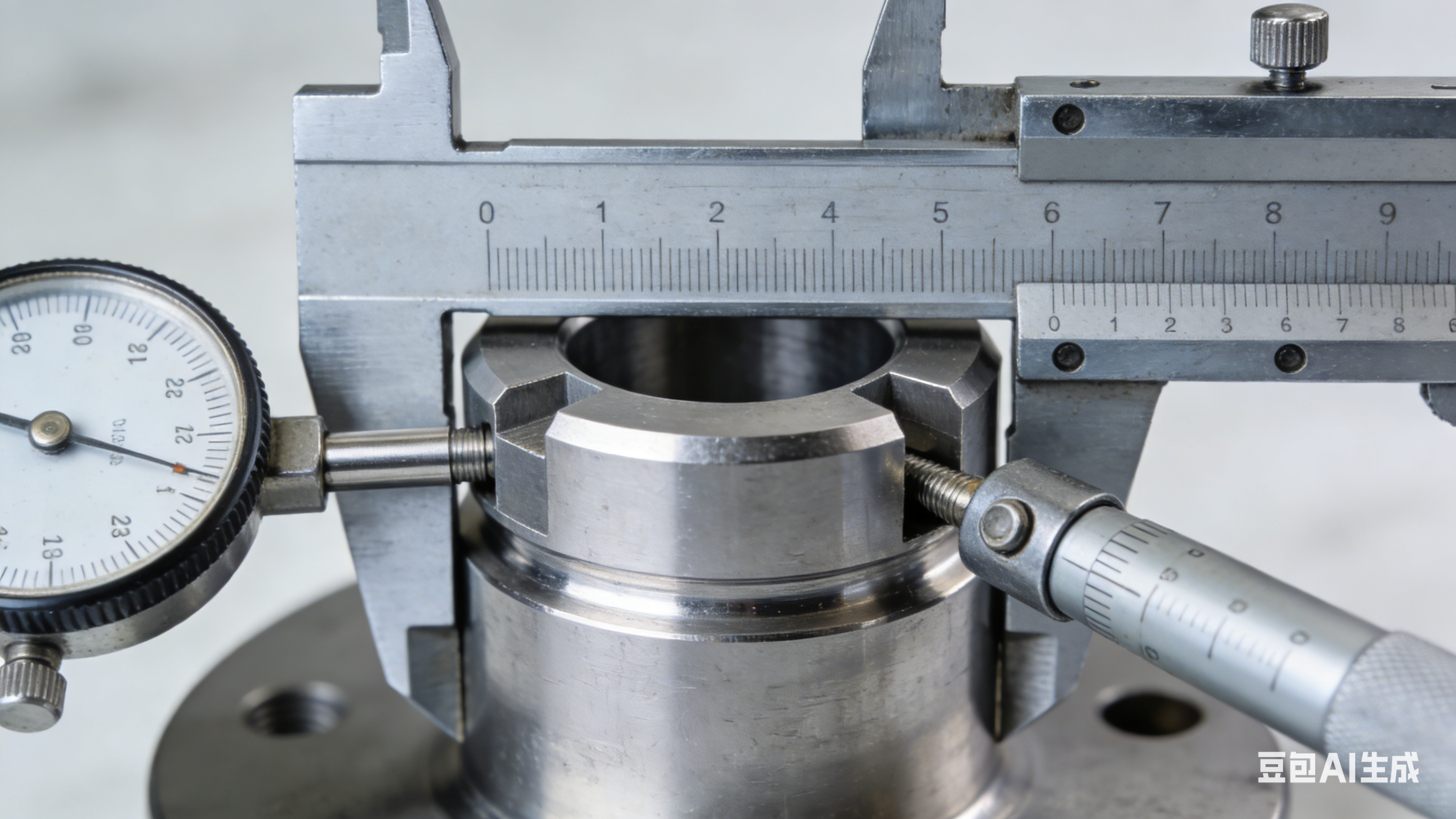
- Coordinate Measuring Machines (CMM): These sophisticated instruments provide precise, automated measurements for complex geometries and tight tolerances. Using both tactile probes and non-contact sensors, CMMs capture dimensional data enabling thorough 3D metrology and geometric verification. They're essential for validating critical features on precision cnc machining parts
- Traditional measurement tools: Micrometers, calipers, and height gauges provide quick verification of standard dimensions. While less automated than CMMs, these instruments remain valuable for in-process checks and first-piece inspections
- Surface roughness testers: Profilometers measure Ra values to verify surface finish requirements. This matters particularly for sealing surfaces, bearing interfaces, and components where friction or wear resistance is critical
- Hardness testing: Rockwell, Brinell, and Vickers testers verify material hardness meets specifications after heat treatment or machining operations
- Non-Destructive Testing (NDT): Methods including ultrasonic testing and magnetic particle inspection assess structural integrity without damaging parts. These techniques detect internal flaws, inclusions, or discontinuities that surface inspection would miss
- Optical inspection: Comparators and vision systems verify profiles, thread forms, and surface defects with high accuracy for stainless steel machining and other materials where visual inspection alone proves insufficient
Statistical Process Control: Preventing Defects Before They Occur
Inspection catches problems after they happen. Statistical Process Control (SPC) prevents problems from occurring in the first place by monitoring manufacturing processes in real-time and identifying trends before they produce out-of-specification parts.
SPC works by tracking key process variables, including tool wear patterns, machine temperature, and dimensional measurements, across production runs. Control charts display this data graphically, making it easy to spot when a process drifts toward tolerance limits. Operators can then make adjustments before producing defective components.
For cnc automotive parts and other high-volume applications, SPC delivers significant advantages:
- Reduced scrap rates: Catching process drift early prevents batches of out-of-spec parts
- Lower inspection costs: Statistical sampling replaces 100% inspection when processes demonstrate stability
- Continuous improvement: Historical data reveals optimization opportunities for cycle time and quality
- Customer confidence: Documented SPC implementation demonstrates manufacturing discipline and reliability
Manufacturers like Shaoyi Metal Technology implement strict SPC protocols as part of their quality management systems. Their approach to automotive precision CNC machining services demonstrates how systematic process control delivers consistent results across production volumes ranging from rapid prototypes to mass production runs.
Understanding Industry Certifications in CNC Manufacturing
Certifications provide independent validation that a manufacturer's quality systems meet rigorous industry standards. According to CNC certification research, these credentials signal to customers, regulators, and partners that a facility meets stringent quality expectations, which is essential for winning contracts in demanding sectors.
Key certifications to understand when evaluating precision machining companies:
ISO 9001: The internationally recognized baseline for quality management systems. ISO 9001 establishes clear procedures for every aspect of production, emphasizing customer focus, process approach, continual improvement, and evidence-based decision-making. Most reputable CNC facilities hold this foundational certification.
IATF 16949: According to BSI Group, this global standard for automotive quality management is mandatory throughout much of the automotive supply chain. Developed by the International Automotive Task Force, IATF 16949 incorporates ISO 9001 while adding requirements for continual improvement, defect prevention, and stringent supplier oversight. Shaoyi Metal Technology's IATF 16949 certification illustrates the level of quality commitment required for automotive supply chain participation, enabling them to deliver high-tolerance components with lead times as fast as one working day.
AS9100: This aerospace-specific standard builds upon ISO 9001 with additional requirements for risk management, stringent documentation, and product integrity control throughout complex supply chains. Aerospace cnc machining facilities must demonstrate this certification to serve major aircraft manufacturers.
ISO 13485: The definitive quality management standard for medical machining applications. This certification outlines strict controls over design, manufacturing, traceability, and risk mitigation essential for patient safety. Medical device manufacturers require suppliers to maintain this certification for any components used in patient-contact applications.
NADCAP: The National Aerospace and Defense Contractors Accreditation Program focuses on special processes critical to aerospace and defense manufacturing, including heat treating, chemical processing, and nondestructive testing. Unlike general quality certifications, NADCAP examines process-specific controls at the highest standards.
Industry-Specific Quality Requirements
Different industries impose distinct documentation and compliance expectations beyond general certifications:
| Industry | Primary Certifications | Special Requirements |
|---|---|---|
| Automotive | IATF 16949, ISO 9001 | PPAP documentation, SPC implementation, complete traceability |
| Aerospace | AS9100, NADCAP | Material certifications, first-article inspection reports, special process accreditation |
| Medical Devices | ISO 13485, FDA 21 CFR Part 820 | Risk management documentation, device history records, complaint handling systems |
| Defense | AS9100, ITAR registration | Security protocols, controlled information handling, government contract compliance |
When evaluating potential manufacturing partners, verify their certifications match your industry requirements. A shop certified only to ISO 9001 cannot serve aerospace programs requiring AS9100, regardless of their machining capabilities.
Quality systems and certifications establish the foundation for reliable manufacturing partnerships. But how do you evaluate potential CNC suppliers beyond checking their certificates? The selection process requires understanding capabilities, communication practices, and alignment with your specific project needs.
Selecting the Right CNC Manufacturing Partner
Finding a qualified CNC machine shop near me sounds straightforward until you realize how many variables separate adequate suppliers from exceptional ones. Your manufacturing partner directly impacts part quality, project timelines, and total costs. According to precision machining evaluation research, a comprehensive assessment typically involves sourcing, quality, and engineering personnel examining capabilities across multiple dimensions.
Whether you're searching for a machinist near me for prototype work or establishing a long-term production relationship, the evaluation criteria remain consistent. Let's break down what separates manufacturing partners who deliver from those who disappoint.
Evaluating Machine Shop Capabilities for Your Project
Machine capabilities form the foundation of any supplier evaluation. A cnc shop near me might have impressive equipment, but does it match your specific part requirements?
Equipment Assessment: From high speed to high torque, multi-axis to Swiss-type, machining shops near me vary dramatically in their equipment mix. You'll want to verify that a prospective partner has machines capable of handling your part's geometry, material, and tolerance requirements. According to PEKO Precision, OEM customers must work with shops to properly understand if machine capability and capacity can meet prospective order needs.
Key equipment considerations include:
- Axis count: 3-axis machines handle simpler geometries while 5-axis centers access complex angles without repositioning
- Work envelope: Maximum part dimensions the machines can accommodate
- Spindle speeds and torque: High-speed spindles suit aluminum while high-torque configurations handle harder materials
- Live tooling: Mill-turn capabilities reduce setups for parts requiring both operations
- Capacity utilization: Shops running at 95% capacity may struggle with your timeline while underutilized facilities might indicate other problems
Process Optimization Capabilities: Beyond raw equipment, evaluate how local machine shops approach manufacturing strategy. Different volumes, setups, cycle times, and material flow seriously affect price, quality, and lead time. Look for evidence of continuous improvement practices like Six Sigma, Lean manufacturing, or Kaizen methodologies. These techniques signal a shop that actively works to deliver better value rather than simply processing orders.
Systems and Infrastructure: A comprehensive MRP or ERP system proves essential for managing complex part mixes. According to manufacturing research, good enterprise systems help with supply chain management, production planning, routing optimization, and shipping coordination. Machinist shops near me that lack robust systems often struggle with on-time delivery as order complexity increases.
Questions to Ask Before Placing Your Order
According to precision machining expertise, the quality of your final product depends on the quality of your manufacturing partner. Asking the right questions upfront prevents costly surprises later.
Before committing to any cnc machine shop near me, gather answers to these critical questions:
- What are your core capabilities? Identify whether the shop specializes in your part type, material, or industry
- Which certifications do you hold? Verify ISO 9001 at minimum; confirm IATF 16949 for automotive, AS9100 for aerospace, or ISO 13485 for medical applications
- Do you outsource any machining processes? Understand the full supply chain and whether secondary operations go to qualified subcontractors
- What is your typical lead time for similar parts? Compare quoted lead times against your project schedule
- How do you handle design changes mid-production? Flexibility matters when specifications evolve
- What inspection equipment do you use? CMM capabilities, surface roughness testers, and calibration programs indicate quality commitment
- Can you provide references from similar projects? Verified track records reduce risk
- What documentation accompanies delivered parts? Inspection reports, material certifications, and traceability records may be required
- Do you offer inventory stocking programs? Blanket orders and scheduled releases can reduce per-part costs and simplify logistics
Scaling from Prototypes to Production Volumes
Your manufacturing needs will likely evolve. A partner capable of growing with you delivers significant long-term value. According to Fictiv manufacturing research, working with an experienced manufacturing partner from the outset offers a streamlined path for parts procurement through the product development process and helps mitigate risk down the road.
Evaluate scalability by examining:
- Prototype-to-production capability: Can the same shop handle your initial 5 prototypes and eventual 5,000-piece production runs?
- Design for manufacturability feedback: Quality partners provide DFM input during prototype phases that prevents costly redesigns later
- Capacity flexibility: Working with a manufacturing partner capable of scaling production up or down, from 1,000 to 100,000 units monthly, using the same processes without constraints can be paramount to success
- Process consistency: Ensure the machining processes used for prototypes translate directly to production, maintaining quality across volumes
For automotive and precision metal components, Shaoyi Metal Technology demonstrates this scalability effectively. Their rapid prototyping to mass production capability, combined with lead times as fast as one working day, addresses the common challenge of finding partners who excel at both development and volume manufacturing. Their expertise in complex chassis assemblies and custom metal bushings illustrates the kind of specialized capability worth seeking when your parts demand both precision and production efficiency.
Partner Evaluation Checklist
Before finalizing your manufacturing partner selection, verify these critical factors:
| Evaluation Category | Key Criteria | Verification Method |
|---|---|---|
| Equipment Capability | Machine types, axis count, work envelope | Facility tour or equipment list review |
| Quality Systems | Certifications, SPC implementation, inspection equipment | Certificate verification, quality manual review |
| Business Stability | Annual revenue, years in operation, financial health | D&B report, direct inquiry, references |
| Supply Chain Management | Material sourcing, secondary operation oversight | Process documentation review |
| Communication | Responsiveness, technical competence, project management | Trial order, reference checks |
| Scalability | Prototype to production capability, capacity headroom | Capacity discussion, volume history |
According to manufacturing evaluation research, OEM customers must also ask tough business questions. Putting faith in a company that faces financial trouble can cause significant supply chain disruptions. Understanding annual revenue, long-term company goals, and debt obligations helps you gauge partnership sustainability.
The right manufacturing partner becomes an extension of your engineering team, contributing expertise that improves your products while meeting delivery commitments consistently. Take time to evaluate thoroughly before committing, and you'll build relationships that deliver value across multiple projects and years of collaboration.
Frequently Asked Questions About CNC Custom Parts
1. How much does a custom CNC part cost?
CNC custom parts pricing varies based on material, complexity, tolerances, and quantity. Simple parts in small runs typically cost $10-$50 per unit, while precision-engineered components with tight tolerances may exceed $160 each. Key cost drivers include machine type required, setup time, surface finish requirements, and post-processing operations. Ordering 10 parts instead of one can reduce per-unit costs by 40-60% since setup charges spread across more pieces.
2. How to design parts for CNC machining?
Effective CNC part design follows Design for Manufacturing principles: specify internal corner radii at least one-third of cavity depth, maintain minimum 0.8mm wall thickness for metals and 1.5mm for plastics, limit pocket depth-to-width ratios under 4:1, and apply tight tolerances only to functional features. Avoid sharp internal corners, excessively thin walls, and unnecessary undercuts. Submit STEP files with complete 2D drawings including GD&T callouts, thread specifications, and surface finish requirements.
3. What materials work best for CNC custom parts?
Material selection depends on your application requirements. Aluminum 6061 offers excellent machinability and corrosion resistance for general components, while 7075 provides 84% higher tensile strength for demanding applications. Stainless steel 304 and 316 handle corrosive environments. Bronze alloys excel in bearings and wear applications. Engineering plastics like Delrin deliver precision with low friction, while PEEK handles extreme temperatures and chemicals in aerospace and medical applications.
4. What tolerances can CNC machining achieve?
Standard CNC tolerances range from ±0.005" to ±0.010" for general components. Precision machining achieves ±0.001" to ±0.002" for mating parts and critical features. Swiss machining delivers ultra-precision tolerances as tight as ±0.0002" for small-diameter components. Tighter specifications increase costs through slower feeds, frequent tool changes, and additional inspection. Apply tight tolerances only to functional features while using general tolerances elsewhere.
5. When should I choose CNC machining over 3D printing or injection molding?
Choose CNC machining when you need superior dimensional accuracy, isotropic material strength, smooth surface finishes, or production-grade metals. CNC is cost-effective for 1-500 metal parts or 1-1,000 plastic parts. Select 3D printing for complex internal geometries, quantities under 10, or 24-hour prototyping needs. Injection molding becomes economical above 1,000 identical plastic parts with stable designs, though it requires $5,000-$100,000 tooling investment.