 Small batches, high standards. Our rapid prototyping service makes validation faster and easier —

Blank Holder Force Calculation: Stop Wrinkling Before It Ruins Your Draw

Understanding Blank Holder Force Fundamentals
Ever watched a perfectly good sheet metal blank crumple into unusable waves during a deep draw? That frustrating outcome often traces back to one critical factor: blank holder force. This fundamental parameter determines whether your forming operation produces flawless cups and shells or scrap parts destined for the recycling bin.
Blank holder force (BHF) is the clamping pressure applied to the flange area of a sheet metal blank during deep drawing operations. Think of it as the controlled grip that guides material flow from the flange into the die cavity. When you apply the right amount of force, the blank slides smoothly over the die radius, forming a uniform wall thickness without defects. Get it wrong, and you'll quickly understand why mastering blank holder force calculation matters so much in precision metal forming.
What Blank Holder Force Controls in Deep Drawing
The physics behind BHF connects directly to how metal behaves under stress. As the punch descends and draws material into the die, the flange experiences compressive stresses in the circumferential direction. Without adequate restraint, these stresses cause the flange to buckle and wrinkle. The blank holder provides that essential restraint by applying pressure perpendicular to the sheet surface.
Proper blank holder force calculation delivers three primary outcomes:
- Controlled material flow: The force regulates how quickly and uniformly the blank feeds into the die cavity, preventing uneven wall formation
- Prevention of wrinkling: Adequate pressure suppresses compressive buckling in the flange region where circumferential stresses are highest
- Avoidance of excessive thinning: By balancing friction and flow, proper BHF prevents localized stretching that leads to wall fractures
These outcomes depend heavily on understanding the relationship between yield strength, yield stress and yield strength characteristics of your specific material. The yielding force required to initiate plastic deformation sets the baseline for how much pressure you need to control material behavior during the draw.
The Balance Between Wrinkling and Tearing
Imagine walking a tightrope between two failure modes. On one side, insufficient BHF allows the flange to wrinkle as compressive stresses exceed the material's buckling resistance. On the other side, excessive force creates such high friction that the wall stretches beyond its forming limits, resulting in tears or fractures near the punch radius.
When BHF is too low, you'll notice wavy flanges and buckled walls that make parts dimensionally unacceptable. The material essentially takes the path of least resistance, buckling upward rather than flowing smoothly into the die. This differs significantly from operations like tapered cutting where controlled material removal follows predictable paths.
When BHF is too high, the excessive friction prevents adequate material flow. The punch continues its stroke, but the flange can't feed fast enough to supply the wall. This creates dangerous thinning, typically at the punch radius where stress concentrations are highest. Unlike tapered cutting operations that remove material progressively, deep drawing redistributes material, and excessive restraint disrupts this redistribution catastrophically.
The optimal BHF window depends on several interconnected factors: drawing ratio (the relationship between blank diameter and punch diameter), material thickness, and the specific yield strength of your sheet stock. A higher drawing ratio demands more careful force control because the flange area is larger and compressive stresses are more significant. Thinner materials require proportionally lower forces but are more sensitive to variations.
For engineers and die designers, understanding these fundamentals provides the foundation for accurate calculations. You need to grasp why the force matters before you can determine how much force to apply. The sections ahead will build on these concepts, translating physics into practical formulas and real-world methodologies that produce consistent, defect-free parts.
Core Formulas for Blank Holder Force Calculation
Now that you understand why blank holder force matters, let's translate those fundamentals into actual numbers. The mathematical formulas for blank holder force calculation bridge the gap between theoretical understanding and shop-floor application. These equations give you concrete values to program into your press or specify in your die design documentation.
The beauty of these formulas lies in their practicality. They account for geometry, material properties, and the elastic modulus of metals you're forming. Whether you're drawing mild steel cups or aluminum alloy housings, the same foundational equation applies with material-specific adjustments.
The Standard BHF Formula Explained
The primary formula for calculating blank holder force centers on one key concept: you need enough pressure across the flange area to prevent wrinkling without restricting material flow. Here's the standard equation:
BHF = π/4 × [(D₀² - (d + 2rd)²)] × p
Sounds complex? Let's break it apart. This formula calculates the total force by multiplying the effective flange area by the specific blank holder pressure required for your material. The result gives you the force in Newtons when you use consistent SI units.
The term π/4 × [(D₀² - (d + 2rd)²)] represents the annular area of the flange that sits under the blank holder. Picture a doughnut-shaped ring of material. The outer boundary is your blank diameter, and the inner boundary is where the material transitions into the die cavity. This area decreases as the draw progresses, which is why some operations benefit from variable force control.
Breaking Down Each Variable
Understanding each variable helps you apply the formula correctly and troubleshoot when results don't match expectations:
- D₀ (Blank Diameter): The initial diameter of your circular blank before forming. This value comes directly from your blank development calculations based on the finished part geometry.
- d (Punch Diameter): The outer diameter of your punch, which determines the inner diameter of your drawn cup. This is typically a fixed design parameter.
- rd (Die Corner Radius): The radius at the die entry where material bends and flows into the cavity. A larger radius reduces drawing force but increases the effective flange area slightly.
- p (Specific Blank Holder Pressure): The pressure per unit area applied to the flange, expressed in MPa. This variable requires careful selection based on material properties.
The specific pressure value p deserves special attention because it connects directly to the yield strength yield stress characteristics of your material. Materials with higher yield in engineering applications require proportionally higher specific pressures to maintain adequate control during forming.
Recommended Specific Pressure Values by Material
Selecting the right specific pressure is where material science meets practical forming. The tensile modulus steel exhibits differs significantly from aluminum or copper alloys, and these differences influence how aggressively you need to restrain the flange. The modulus of elasticity of steel also affects springback behavior, though its primary influence on BHF comes through the yield strength relationship.
| Material | Specific Pressure (p) | Typical Yield Strength Range | Notes |
|---|---|---|---|
| Mild Steel | 2-3 MPa | 200-300 MPa | Start at lower end for thinner gauges |
| Stainless Steel | 3-4 MPa | 200-450 MPa | Higher work hardening requires upper range |
| Aluminum Alloys | 1-2 MPa | 100-300 MPa | Sensitive to lubrication conditions |
| Copper Alloys | 1.5-2.5 MPa | 70-400 MPa | Varies significantly with alloy composition |
Notice how the specific pressure correlates with yield strength ranges. Higher-strength materials generally need higher holding pressures because they resist deformation more strongly. When you're working with a material at the upper end of its strength range, select pressures toward the higher recommended values.
Empirical Versus Analytical Approaches
When should you rely on the standard formula, and when do you need more sophisticated methods? The answer depends on part complexity and your production requirements.
Use empirical formulas when:
- Drawing simple axisymmetric shapes like cylindrical cups
- Working with well-characterized materials and established processes
- Production volumes justify trial-and-error optimization
- Part tolerances allow some variation in wall thickness
Consider analytical or simulation-based approaches when:
- Forming complex non-axisymmetric geometries
- Drawing high-strength or exotic materials with limited data
- Tight tolerances demand precise control
- Production volumes don't permit extensive tryout iterations
The standard formula provides an excellent starting point for most applications. You'll typically achieve 80-90% accuracy on initial calculations, then refine based on tryout results. For critical applications or new materials, combining calculated values with simulation validation significantly reduces development time and scrap rates.
With these formulas in hand, you're ready to calculate theoretical BHF values. However, real-world forming involves friction between tool surfaces and your blank, and those friction effects can significantly alter your results.
Friction Coefficients and Lubrication Effects
You've calculated your blank holder force using the standard formula, plugged in all the right values, and the number looks good on paper. But when you run the first parts, something's off. The material isn't flowing the way you expected, or you're seeing surface scratches that weren't in the plan. What happened? The answer often lies in friction, the invisible variable that can make or break your blank holder force calculation.
Friction between the blank, die, and blank holder surfaces directly influences how much force actually restrains material flow. Ignore it, and your carefully calculated BHF becomes little more than an educated guess. Account for it properly, and you gain precise control over your forming process.
How Friction Changes Your Calculations
The relationship between friction and blank holder force follows a straightforward principle: higher friction amplifies the restraining effect of any given force. When friction coefficient increases, the same BHF produces greater resistance to material flow. This means your calculated force might be too aggressive if friction is higher than assumed, or too weak if lubrication reduces friction below expected levels.
The modified formula that accounts for friction connects three critical parameters:
Drawing Force = BHF × μ × e^(μθ)
Here, μ represents the friction coefficient between contacting surfaces, and θ is the wrap angle in radians where material contacts the die radius. The exponential term captures how friction compounds as material wraps around curved surfaces. Even small changes in μ create significant differences in the force required to draw material into the die cavity.
Consider what happens when you double your friction coefficient from 0.05 to 0.10. The drawing force doesn't simply double. Instead, the exponential relationship means force increases more dramatically, especially for geometries with larger wrap angles. This explains why lubrication selection matters as much as your initial BHF calculation.
Typical friction coefficients vary widely depending on surface conditions and lubricants:
- Dry steel-on-steel: 0.15-0.20 (rarely acceptable for production forming)
- Light oil lubrication: 0.10-0.12 (suitable for shallow draws and low-strength materials)
- Heavy drawing compounds: 0.05-0.08 (standard for moderate to deep draws)
- Polymer films: 0.03-0.05 (optimal for demanding applications and high-strength materials)
These ranges represent starting points. Actual coefficients depend on surface roughness, temperature, drawing speed, and lubricant application consistency. When your calculated BHF produces unexpected results, friction coefficient variation is often the culprit.
Lubrication Strategies for Optimal Material Flow
Selecting the right lubricant involves matching friction characteristics to your forming requirements. Lower friction allows material to flow more freely, reducing the BHF needed to prevent tearing. However, excessively low friction might require higher BHF to prevent wrinkling since the material offers less natural resistance to buckling.
Hot dipped galvanized materials present unique challenges that illustrate this balance. The zinc coating on hot dipped galvanized steel creates different friction characteristics compared to bare steel. The softer zinc layer can act as a built-in lubricant under light pressure, but it also transfers to die surfaces over extended production runs. This hot dip galvanized zinc coating behavior means your friction coefficient may drift during a production run, requiring adjusted BHF settings or more frequent die maintenance.
When forming galvanized materials, many engineers start with lower specific pressures and increase gradually during tryout. The zinc coating's lubricating effect often means you need 10-15% less BHF compared to uncoated steel of the same grade. However, coating thickness variations between suppliers can affect consistency, making documentation and incoming material verification essential.
How Strain Hardening Affects Friction Requirements
Here's where forming gets interesting. As the drawing stroke progresses, the material isn't the same metal it was when you started. Strain hardening and work hardening phenomena transform the material properties in real-time, and these changes affect friction behavior throughout the operation.
During deep drawing, the flange material experiences plastic deformation before entering the die cavity. This strain hardening increases the material's yield strength locally, sometimes by 20-50% depending on the alloy and strain level. Work hardening makes the material stiffer and more resistant to further deformation, which changes how it interacts with die surfaces.
What does this mean for friction? Harder, work-hardened material generates different friction characteristics than the softer initial stock. Surface asperities behave differently, lubricant films may thin under higher contact pressures, and the overall friction coefficient can increase as the draw progresses. This strain hardening and work hardening progression explains why constant BHF sometimes produces inconsistent results, especially on deep draws where significant material transformation occurs.
Practical implications include:
- Lubricant films must withstand increasing contact pressures as material hardens
- Die surface finishes become more critical late in the stroke when friction tends to rise
- Variable BHF systems can compensate for changing friction by adjusting force throughout the stroke
- Materials with high work hardening rates may benefit from more aggressive lubrication strategies
Understanding this dynamic relationship between material transformation and friction helps explain why experienced die setters often adjust BHF based on factors that don't appear in standard formulas. They're compensating for friction effects that change during each forming cycle.
With friction effects now part of your calculation toolkit, you're ready to put everything together in a complete worked example with actual numbers and units.

Step-by-Step Calculation Methodology
Ready to put theory into practice? Let's walk through a complete blank holder force calculation from start to finish using real numbers you might encounter on the shop floor. This worked example demonstrates exactly how each formula component comes together, giving you a template you can adapt for your own applications.
The best way to master these calculations is by working through an actual scenario. We'll calculate the BHF for a common deep drawing operation: forming a cylindrical cup from a circular blank. Along the way, you'll see how material properties like yield stress of steel influence your decisions and how each step builds toward your final force value.
Step-by-Step Calculation Walkthrough
Before diving into numbers, let's establish a systematic approach. Following these steps in order ensures you don't miss critical factors that affect accuracy. This methodology works whether you're calculating force for mild steel grades or high-strength alloys.
- Determine blank and punch dimensions: Gather all geometric parameters including blank diameter (D₀), punch diameter (d), and die corner radius (rd). These values typically come from your part drawings and die design specifications.
- Calculate flange area under holder: Apply the annular area formula to find the surface area where blank holder pressure acts. This area determines how much total force results from your selected specific pressure.
- Select appropriate specific pressure based on material: Reference material property tables to choose the correct pressure coefficient (p). Consider the yield strength of steel or other materials, thickness, and surface conditions.
- Apply the formula with unit conversions: Plug all values into the BHF equation, ensuring consistent units throughout. Convert final results to practical units like kilonewtons for press programming.
- Verify against drawing ratio limits: Check that your geometry falls within acceptable drawing ratio limits for the material and that calculated force aligns with equipment capabilities.
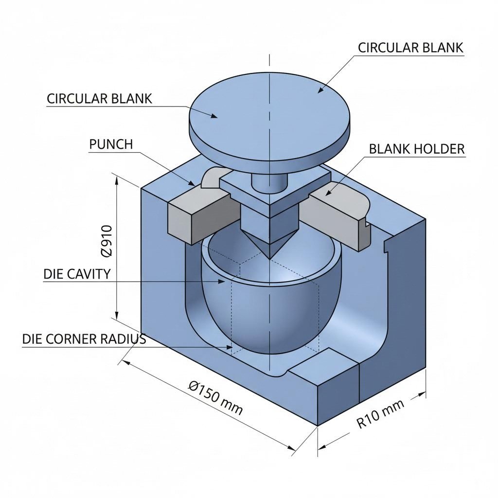
Worked Example with Real Values
Let's calculate the blank holder force for a practical scenario that represents typical production conditions.
Given parameters:
- Blank diameter (D₀): 150 mm
- Punch diameter (d): 80 mm
- Die corner radius (rd): 8 mm
- Material: Mild steel, 1.2 mm thickness
- Yield stress: approximately 250 MPa (typical for common steel grades)
Step 1: Confirm Dimensions
First, verify your drawing ratio to ensure the operation is feasible. The drawing ratio (β) equals blank diameter divided by punch diameter:
β = D₀ / d = 150 / 80 = 1.875
For mild steel in a first draw operation, the maximum recommended drawing ratio typically ranges from 1.8 to 2.0. Our ratio of 1.875 falls within acceptable limits, so we can proceed confidently.
Step 2: Calculate Flange Area
The flange area under the blank holder uses the annular area formula. We need the effective inner diameter, which accounts for the die corner radius:
Effective inner diameter = d + 2rd = 80 + 2(8) = 96 mm
Now calculate the annular area:
A = π/4 × [(D₀)² - (d + 2rd)²]
A = π/4 × [(150)² - (96)²]
A = π/4 × [22,500 - 9,216]
A = π/4 × 13,284
A = 0.7854 × 13,284
A = 10,432 mm² (or approximately 104.32 cm²)
Step 3: Select Specific Pressure
For mild steel with a yield stress in the 200-300 MPa range, the recommended specific pressure falls between 2-3 MPa. Given our 1.2 mm thickness (not extremely thin) and standard yield strength of steel in this grade, we'll select:
p = 2.5 MPa (middle of the recommended range)
This selection accounts for typical lubrication conditions and provides margin against both wrinkling and tearing.
Step 4: Apply the Formula
Now we combine area and pressure to find total force:
BHF = A × p
BHF = 10,432 mm² × 2.5 MPa
Since 1 MPa = 1 N/mm², the calculation becomes:
BHF = 10,432 mm² × 2.5 N/mm²
BHF = 26,080 N
BHF = 26.08 kN
Step 5: Verify Against Limits
With our calculated force of approximately 26 kN, we need to confirm this value makes sense for our equipment and die design.
Always compare your calculated BHF against two critical limits: maximum press blank holder capacity and die design specifications. Your calculated force must fall below press capacity while remaining above the minimum threshold needed to prevent wrinkling. For this example, a press with 50+ kN blank holder capacity provides adequate margin, and the calculated 26 kN should effectively control material flow for our geometry and steel grade.
Interpreting Your Results
The 26 kN result represents your starting point for tryout. In practice, you might adjust this value by ±10-15% based on actual material behavior and lubrication effectiveness. Here's how to interpret the calculation:
| Parameter | Calculated Value | Practical Consideration |
|---|---|---|
| Flange Area | 10,432 mm² | Decreases as draw progresses |
| Specific Pressure | 2.5 MPa | Adjust based on actual yield stress results |
| Total BHF | 26.08 kN | Starting value for press setup |
| Drawing Ratio | 1.875 | Within safe limits for single draw |
If your first tryout parts show slight wrinkling, increase pressure toward 2.8-3.0 MPa. If you observe thinning near the punch radius or early signs of tearing, reduce toward 2.0-2.2 MPa. The calculation provides scientific grounding, but final optimization requires observing actual material behavior.
Notice how the yield stress of the specific steel grade influenced our pressure selection. Higher-strength steel grades would push you toward the upper pressure range, while softer drawing-quality steels might allow lower values. Always verify material certifications match your assumptions before production runs.
With a solid calculated value in hand, you can further refine your approach by understanding how Forming Limit Diagrams reveal the boundaries between successful forming and failure modes.
Forming Limit Diagrams and Force Optimization
You've calculated your blank holder force and even accounted for friction effects. But how do you know if that calculated value will actually produce good parts? This is where Forming Limit Diagrams become your validation tool. A formability limit diagram maps the boundary between successful forming and failure, giving you visual confirmation that your BHF settings keep the operation in safe territory.
Think of an FLD as a roadmap for your material. It shows exactly how much strain the sheet can handle before something goes wrong. By understanding where your forming operation falls on this diagram, you can predict whether your blank holder force calculation will deliver wrinkle-free, tear-free parts before you ever run the first blank.
Reading Forming Limit Diagrams for BHF Optimization
A Forming Limit Diagram plots major strain (the largest principal strain) on the vertical axis against minor strain (the strain perpendicular to major strain) on the horizontal axis. The resulting curve, often called the Forming Limit Curve (FLC), represents the threshold where material failure begins. Any strain combination below this curve is safe; anything above risks necking, tearing, or fracture.
When you examine an FLD, you'll notice it isn't symmetrical. The curve typically dips lowest near the center where minor strain equals zero (plane strain condition) and rises on both sides. This shape reflects how material behaves differently under various strain states. Biaxial stretching on the right side of the diagram and drawing/compression on the left side each have distinct failure limits.
Understanding the key zones on an FLD helps you interpret where your operation falls:
- Safe forming region: Strain combinations well below the FLC where material flows without risk of failure. This is your target zone for reliable production.
- Marginal zone: The area just below the FLC where parts may pass inspection but have reduced safety margin. Material variations or process drift could push into failure.
- Necking/failure zone: Strain combinations at or above the FLC where localized thinning leads to cracks and tears. Parts formed here will fail quality checks.
- Wrinkling zone: The lower-left region where excessive compressive minor strains cause buckling. This indicates insufficient blank holder force to control material flow.
The relationship between tensile strength vs yield strength affects where your material's FLC sits. Materials with higher elongation before necking typically have FLCs positioned higher on the diagram, offering greater formability windows. Conversely, high-strength materials with lower elongation have FLCs closer to the origin, demanding more precise BHF control.
Connecting FLD Data to Force Settings
Here's where the FLD becomes practical for blank holder force optimization. Your BHF directly influences the strain path your material follows during forming. Increase the force, and you shift the strain path toward more biaxial stretching (moving right on the diagram). Decrease the force, and the path shifts toward drawing conditions (moving left toward potential wrinkling).
Imagine your current BHF produces a strain path that passes dangerously close to the wrinkling zone. The FLD tells you immediately: increase your calculated force to shift the path upward and rightward, away from compressive failure. Conversely, if strain measurements show you're approaching the necking limit, reducing BHF allows more material flow, shifting the path away from the failure curve.
Different materials require fundamentally different approaches because their FLDs vary significantly:
- Mild steel: Typically offers generous forming windows with FLCs positioned relatively high. Standard BHF calculations work well, with moderate adjustment range during tryout.
- Aluminum alloys: Generally have lower FLCs compared to steel of similar thickness, demanding tighter BHF control. The modulus of elasticity of aluminum also influences springback behavior, affecting final part dimensions even when forming succeeds.
- Stainless steel: High work hardening rates shift the FLC during forming, meaning strain paths must account for material transformation. Initial BHF settings often require refinement as production data accumulates.
For aluminum alloys specifically, the lower modulus of elasticity of aluminum compared to steel means these materials deflect more under given loads. This affects how blank holder pressure distributes across the flange and can create localized strain concentrations if pressure distribution isn't uniform.
To use FLD data effectively in your workflow, measure strains on trial parts using circle grid analysis or digital image correlation. Plot these measured strains on your material's FLD. If points cluster near the wrinkling zone, increase BHF. If points approach the FLC, reduce force or improve lubrication. This iterative validation transforms your calculated BHF from a theoretical value into a production-proven setting.
The connection between FLD analysis and blank holder force calculation bridges what many engineers treat as separate disciplines. Your formula gives you a starting number; the FLD confirms whether that number actually works for your specific geometry and material combination. When these tools work together, you achieve first-pass success rates that trial-and-error approaches simply cannot match.
While FLD validation works well for constant-force systems, some applications benefit from adjusting force throughout the drawing stroke. Variable blank holder force systems offer this capability, opening new possibilities for challenging geometries.

Variable Blank Holder Force Systems
What if your blank holder force could adapt in real-time as the punch descends? Instead of applying one fixed pressure throughout the entire stroke, imagine a system that starts with higher force to prevent initial wrinkling, then gradually reduces pressure as the flange area shrinks. This isn't science fiction. Variable blank holder force (VBF) systems deliver exactly this capability, and they're transforming how manufacturers approach challenging deep drawing operations.
Constant BHF works well for straightforward geometries and forgiving materials. But when you're pushing drawing ratios to their limits, working with materials prone to deformation hardening, or forming complex shapes where strain paths vary dramatically across the part, a single force value simply can't optimize every stage of the draw. VBF systems address this limitation by treating blank holder force as a dynamic process variable rather than a fixed parameter.
When Variable Force Outperforms Constant Force
Consider what actually happens during a deep draw. At the beginning of the stroke, the full flange area sits under the blank holder, and compressive stresses are at their highest. This is when wrinkling risk peaks, demanding substantial restraining force. As the punch continues downward, material flows into the die cavity, reducing the flange area progressively. By the end of the stroke, only a small ring of material remains under the holder.
Here's the problem with constant force: the pressure that prevents wrinkling at stroke start may create excessive friction and tearing risk as the flange shrinks. Conversely, a force optimized for late-stroke conditions leaves you vulnerable to early wrinkling. You're forced to compromise, accepting suboptimal conditions at some point during every cycle.
VBF systems eliminate this compromise by matching force to instantaneous conditions. The yielding load required to initiate plastic flow in the flange changes as material work-hardens during forming. A properly programmed VBF profile accounts for these changes, maintaining optimal restraint throughout the operation. Materials with high deformation hardening rates benefit especially from this approach since their properties shift significantly during each stroke.
Hydroforming operations demonstrate VBF principles at their most sophisticated. In hydroforming, fluid pressure replaces the rigid punch, and pressure profiles must be precisely controlled to achieve uniform material flow. These systems routinely vary pressure by 50% or more during a single forming cycle, proving that dynamic force control enables geometries impossible with constant-pressure approaches. The lessons from hydroforming apply directly to conventional deep drawing with mechanical blank holders.
Spin forming represents another application where variable force proves essential. As the spinning tool progressively shapes material over a mandrel, the optimal restraining force changes continuously. Engineers working in spin forming have long understood that static force settings limit what's achievable.
Modern VBF Control Technologies
Implementing variable blank holder force requires equipment capable of precise, repeatable force modulation. Modern VBF systems typically use one of three approaches: hydraulic cushions with servo control, nitrogen die cushions with adjustable pressure, or mechanically programmable systems with cam-driven force profiles.
Servo-hydraulic systems offer the greatest flexibility. Programmable controllers adjust oil pressure to the blank holder cylinders based on punch position, time, or force feedback signals. You can create virtually any force profile the physics allow, then store and recall programs for different parts. Setup involves programming the profile, running trial parts, and refining based on results.
Nitrogen-based systems provide simpler implementation at lower cost. Pressurized nitrogen cylinders create the holding force, and adjustable regulators or multi-stage cylinders allow some force variation during the stroke. While less flexible than servo-hydraulic approaches, nitrogen systems handle many variable-force applications adequately.
| Criteria | Constant BHF | Variable BHF |
|---|---|---|
| Part Complexity Suitability | Simple axisymmetric shapes, shallow draws | Complex geometries, deep draws, asymmetric parts |
| Equipment Requirements | Standard press with basic cushion | Servo-hydraulic or programmable cushion system |
| Setup Time | Faster initial setup, single force value | Longer development, but more repeatable production |
| Quality Consistency | Acceptable for simple parts | Superior for challenging applications |
| Capital Investment | Lower upfront cost | Higher initial investment, often justified by quality gains |
| Material Utilization | Standard blank sizes required | Potential for smaller blanks due to better flow control |
Selecting Between Constant and Variable Approaches
Not every application justifies VBF complexity. Making the right choice requires evaluating several factors systematically.
Part geometry drives the initial assessment. Shallow draws with modest drawing ratios rarely need variable force. Deep draws approaching material limits, parts with varying wall angles, or geometries that create uneven flange recession benefit most from VBF capability.
Material properties influence the decision significantly. Materials with pronounced deformation hardening characteristics see greater benefit from variable profiles. High-strength steels, certain aluminum alloys, and stainless grades often justify VBF investment based on material behavior alone.
Production volume affects the economics. Low-volume production may not justify VBF equipment costs unless part complexity absolutely demands it. High-volume applications spread equipment investment across more parts, making VBF economically attractive even for modest quality improvements.
Current defect rates provide practical guidance. If you're achieving acceptable quality with constant force, VBF may offer diminishing returns. If wrinkling or tearing defects persist despite optimized constant-force settings, VBF often provides the solution that calculation refinements alone cannot.
When evaluating VBF systems, request data from equipment suppliers showing before-and-after results for applications similar to yours. The best evidence comes from demonstrated improvements on comparable parts, not theoretical capabilities.
Variable force control represents the advanced end of blank holder force optimization. But before implementing sophisticated control strategies, you need reliable methods to diagnose when force settings aren't working as intended.
Troubleshooting Common Calculation Errors
Your blank holder force calculation looked perfect on paper. The formula checked out, the material data was accurate, and the press settings matched your specifications. Yet the parts coming off the line tell a different story: wavy flanges, cracked walls, or mysterious scratches that shouldn't exist. What went wrong?
Even experienced tool and die makers encounter situations where calculated values don't translate to production success. The gap between theory and reality often reveals itself through specific defect patterns that point directly to BHF issues. Learning to read these patterns transforms you from someone who reacts to problems into someone who solves them systematically.
Diagnosing Wrinkling and Tearing Issues
Every defect tells a story. When you examine a failed part, the location, pattern, and severity of the defect provide diagnostic clues that guide your corrective actions. A skilled die maker doesn't just see a wrinkled flange; they see evidence of specific force imbalances that their calculations didn't anticipate.
Wrinkling indicates insufficient restraint. When blank holder force falls below the threshold needed to suppress compressive buckling, the flange material takes the path of least resistance and buckles upward. You'll notice wavy patterns in the flange area, sometimes extending into the wall as the wrinkled material gets drawn into the die cavity. The yield point for steel or other materials sets the baseline resistance to this buckling, but geometry and friction conditions determine whether your applied force exceeds that threshold.
Tearing signals excessive restraint or inadequate material flow. When BHF creates too much friction, the punch continues its stroke while the flange can't feed fast enough. The wall stretches beyond its forming limits, typically failing at the punch radius where stress concentrations peak. Cracks may appear as small splits that propagate during forming or as complete wall fractures that separate the cup from its flange.
The following diagnostic matrix connects visual observations to likely causes and corrective actions:
| Defect Type | Visual Indicators | Likely BHF Issue | Corrective Action |
|---|---|---|---|
| Flange Wrinkling | Wavy, rippled flange surface; buckles radiating from center | Force too low; inadequate restraint against compressive stress | Increase specific pressure 15-25%; verify uniform holder contact |
| Wall Wrinkling | Buckles or waves in cup wall; irregular wall surface | Severely insufficient force; wrinkles drawn into cavity | Increase force significantly; check die clearance |
| Punch Radius Tearing | Cracks or splits at bottom radius; circumferential fractures | Force too high; excessive friction restricting flow | Reduce force 10-20%; improve lubrication |
| Wall Fracture | Complete wall separation; jagged tear lines | Severely excessive force or material at forming limit | Reduce force substantially; verify drawing ratio limits |
| Excessive Thinning | Localized necking; visible thickness reduction in wall | Force marginally high; strain approaching FLD limit | Reduce force 5-15%; enhance lubrication at die radius |
| Surface Scratches | Galling marks; score lines parallel to draw direction | Force may be appropriate but friction too high locally | Inspect die surfaces; improve lubrication; polish die radius |
Notice how similar defects can have different root causes. A tool and die specialist learns to distinguish between force-related issues and other process variables by examining defect patterns closely. Circumferential cracks suggest radial tension from excessive BHF, while longitudinal cracks might indicate material defects or improper die clearance rather than force problems.
Using Measurements to Confirm BHF Issues
Visual inspection gets you started, but measurements confirm your diagnosis. Two analytical approaches provide quantitative evidence that your blank holder force calculation needs adjustment.
Thickness measurements reveal how material distributed during forming. Using a ball micrometer or ultrasonic thickness gauge, measure wall thickness at multiple points around the cup circumference and at various heights. Uniform thinning of 10-15% is normal. Localized thinning exceeding 20-25% indicates strain concentrations that often trace back to BHF issues.
Compare thickness profiles from parts formed at different force settings. If increasing BHF correlates with increased thinning at the punch radius, you've confirmed excessive force as the cause. If reducing BHF eliminates thinning but introduces wrinkling, you've identified your operating window and need to optimize within that range.
Strain analysis using circle grid patterns or digital image correlation provides deeper insight. By measuring how printed circles deform into ellipses during forming, you can plot actual strain paths on a Forming Limit Diagram. If measured strains cluster near the wrinkling zone, increase force. If they approach the necking limit, reduce force or address friction conditions.
When documenting defects for a tool and die maker or engineering team, include photographs with measurement annotations showing exactly where problems occur. This documentation accelerates troubleshooting by providing clear evidence rather than subjective descriptions. Understanding weld symbol conventions isn't directly relevant here, but the same principle of clear technical communication applies: precise documentation enables precise solutions.
Systematic Troubleshooting Approach
When parts fail inspection, resist the temptation to immediately adjust BHF. A systematic approach ensures you identify the actual root cause rather than masking one problem while creating another. Even a groove weld connecting components requires proper sequencing for quality results; troubleshooting BHF issues demands similar discipline.
Follow this troubleshooting sequence before adjusting your calculated force:
- Verify material properties: Confirm incoming material matches specifications. Check mill certifications for yield strength, thickness tolerance, and surface condition. Material variation between heats can shift optimal BHF by 10-20%.
- Check lubrication condition: Inspect lubricant coverage, viscosity, and contamination. Inadequate or degraded lubrication creates friction variations that mimic BHF problems. Ensure consistent application across the blank surface.
- Measure actual BHF versus calculated: Use load cells or pressure gauges to verify the press delivers your programmed force. Hydraulic system drift, nitrogen cylinder leakage, or mechanical wear can reduce actual force below settings.
- Inspect die surfaces: Examine blank holder and die surfaces for wear, galling, or debris. Localized damage creates uneven pressure distribution that calculations assume is uniform.
- Validate blank dimensions: Confirm blank diameter and thickness match design values. Oversized blanks increase flange area, requiring proportionally higher force than calculated.
Only after completing this verification sequence should you adjust your blank holder force calculation. If material, lubrication, equipment, and geometry all check out correctly, then recalculating with adjusted specific pressure becomes the appropriate response.
Document every troubleshooting step and its outcome. This record becomes invaluable for future production runs and helps train less experienced operators. A well-documented troubleshooting history often reveals patterns: perhaps material from a specific supplier consistently requires higher BHF, or summer humidity affects lubrication performance.
The diagnostic skills covered here help you respond effectively when problems occur. But what if you could predict and prevent these issues before cutting the first production blank? That's where simulation-driven validation transforms your approach to blank holder force optimization.

CAE Simulation for Force Validation
What if you could test your blank holder force calculation before cutting a single tool steel blank? Modern CAE simulation makes this possible, transforming how engineers validate and refine their force settings. Instead of relying solely on formulas and trial-and-error tryouts, you can now visualize exactly how material will flow, where thinning will occur, and whether wrinkling risks lurk in your design before committing to production tooling.
Finite element analysis (FEA) has revolutionized deep drawing optimization. By creating virtual models of your forming operation, simulation software predicts material behavior under various BHF conditions with remarkable accuracy. The properties you've been calculating with, like Young's modulus of steel and yield strength values, become inputs that drive sophisticated mathematical models of plastic deformation. These simulations reveal problems that formulas alone cannot anticipate, especially for complex geometries where analytical solutions fall short.
Simulation-Driven Force Optimization
Think of FEA simulation as a digital proving ground for your blank holder force calculation. The software divides your blank, punch, die, and blank holder into thousands of small elements, then calculates how each element deforms as the virtual punch descends. Material properties including steel modulus of elasticity, strain hardening curves, and anisotropy coefficients determine how the simulated metal responds to applied forces.
The simulation process follows an iterative workflow. You input your calculated BHF value, run the analysis, and examine the results. If the virtual part shows wrinkling in the flange region, you increase the force and run again. If excessive thinning appears near the punch radius, you reduce force or adjust lubrication parameters. Each iteration takes minutes instead of the hours required for physical tryouts, and you can explore dozens of scenarios before cutting any steel.
What makes modern simulations particularly powerful is their ability to capture phenomena that hand calculations approximate at best. The elastic modulus of steel affects how material springs back after forming, and simulation predicts this springback with enough accuracy to compensate in die design. Work hardening changes material properties during the stroke, and FEA tracks these changes element by element throughout the forming sequence.
Simulation outputs relevant to BHF optimization include:
- Thickness distribution maps: Color-coded visualizations showing wall thickness across the entire part, immediately highlighting areas of excessive thinning or thickening
- Strain path predictions: Plots showing how each location's strain state evolves during forming, directly comparable to your material's Forming Limit Diagram
- Wrinkling risk indicators: Algorithms that detect compressive instabilities before they manifest as visible buckles, flagging regions needing higher restraint
- Force-displacement curves: Graphs of punch force and blank holder force throughout the stroke, verifying your press has adequate capacity
These outputs transform abstract calculations into actionable engineering data. When a simulation shows your calculated BHF produces 22% thinning at the punch radius while your material's limit is 25%, you know you have acceptable margin. When wrinkling indicators light up in the flange, you know exactly where to focus your attention.
From Calculation to Production-Ready Tooling
The journey from validated simulation to production-ready dies requires translating virtual results into physical tooling specifications. This translation demands expertise in both simulation interpretation and practical die engineering. A precise die clearance specification on a tool drawing represents just one detail among hundreds that must be executed correctly for the tooling to perform as simulated.
The modulus of steel you input for simulation must match your actual die materials. Surface finish specifications derived from friction coefficient assumptions must be achieved in die manufacturing. Blank holder flatness tolerances must maintain the uniform pressure distribution your simulation assumed. Every detail connects back to whether your carefully validated BHF delivers expected results in production.
Engineering teams that excel at this translation typically integrate calculation methodology with simulation validation from project inception. They don't treat formulas and FEA as separate activities but as complementary tools in a unified workflow. Initial calculations provide starting points, simulations refine and validate, and production tryouts confirm the entire methodology.
Companies like Shaoyi demonstrate how this integrated approach delivers results. Their advanced CAE simulation capabilities validate blank holder force calculations during die development, catching potential issues before tool steel is ever machined. With IATF 16949 certification ensuring quality management standards throughout the process, their methodology produces measurable outcomes: a 93% first-pass approval rate that reflects calculation accuracy translating successfully into production reality.
This level of first-pass success doesn't happen by accident. It requires systematic validation at every stage: calculating BHF using appropriate formulas, simulating material flow with accurate property data, refining settings based on virtual results, and manufacturing dies that faithfully reproduce simulated conditions. When a specific draw bead geometry appears on die design drawings, it must be machined precisely because even seemingly minor details affect how the complete tool system performs.
For automotive applications where dimensional tolerances are tight and production volumes demand consistent quality, simulation-validated BHF calculations become essential. The cost of simulation software and engineering time pays for itself many times over through reduced tryout iterations, lower scrap rates, and faster time to production. Parts that once required weeks of trial-and-error optimization now achieve target quality in days.
The practical lesson is clear: your blank holder force calculation provides the foundation, but simulation validates whether that foundation will support production success. Together, these tools create a methodology that transforms deep drawing from an art dependent on experience into an engineering discipline driven by data.
With simulation-validated force settings and production-ready tooling, you're positioned to implement a complete calculation workflow that integrates all the methods covered in this guide.
Implementing Your Calculation Workflow
You've explored formulas, friction effects, FLD validation, variable force systems, troubleshooting methods, and simulation capabilities. Now it's time to synthesize everything into a cohesive workflow you can apply consistently across projects. The difference between engineers who struggle with deep drawing and those who achieve reliable results often comes down to systematic methodology rather than raw calculation ability.
A structured approach ensures you don't skip critical steps when deadlines pressure you to move fast. It also creates documentation that makes future jobs faster and helps train team members on proven practices. Whether you're calculating force for a simple cylindrical cup or a complex automotive panel, the same fundamental workflow applies with appropriate adjustments for complexity.
Selecting the Right Calculation Approach
Before diving into calculations, you need to select the methodology that matches your application requirements. Not every job justifies the same level of analytical rigor. A quick prototype run of fifty parts demands a different approach than launching a million-unit annual production program. Understanding the tradeoffs between methods helps you allocate engineering resources effectively.
Three primary approaches exist for blank holder force calculation, each with distinct characteristics that suit different scenarios. The equation to find 0.2 percent offset yield strength from stress-strain data illustrates the level of material characterization each method requires. Simple empirical formulas work with handbook yield strength values, while advanced analytical methods may need complete flow curves showing yield strain steel behavior through plastic deformation.
| Criteria | Empirical Formulas | Analytical Methods | FLD-Based Approaches |
|---|---|---|---|
| Accuracy Level | ±15-25% typical | ±10-15% with good data | ±5-10% with validated FLD |
| Data Requirements | Basic: yield strength, thickness, geometry | Moderate: complete material properties, friction coefficients | Extensive: full FLD curves, strain measurements |
| Complexity | Low; hand calculations sufficient | Moderate; spreadsheet or calculation software | High; requires simulation or physical strain analysis |
| Best-Use Scenarios | Simple axisymmetric parts, early estimates, prototype runs | Production parts, moderate complexity, established materials | Critical applications, new materials, tight tolerances |
| Engineering Time | Minutes to hours | Hours to days | Days to weeks |
| Tryout Iterations Expected | 3-5 adjustments typical | 1-3 adjustments typical | Often first-pass success |
Understanding what yield strength means in practice helps you interpret these accuracy ranges. Yield strength vs tensile strength comparisons reveal that yield strength represents the stress where permanent deformation begins, making it the critical parameter for BHF calculations. If your material data only includes tensile strength, you'll need to estimate yield strength, introducing uncertainty that empirical methods already accommodate but analytical methods struggle to correct.
For most production applications, analytical methods hit the sweet spot between effort and accuracy. You invest enough engineering time to achieve reliable results without the extensive testing that FLD-based validation requires. Reserve FLD approaches for applications where the cost of defects justifies comprehensive upfront analysis: safety-critical components, high-volume programs where small improvements compound across millions of parts, or novel materials without established forming guidelines.
Building Your BHF Calculation Workflow
Regardless of which calculation approach you select, the following workflow ensures comprehensive coverage of all factors that influence blank holder force. Think of this sequence as your quality checklist: completing each step systematically prevents the oversights that cause production problems.
- Gather material data and geometry specifications: Collect all inputs before starting calculations. This includes blank diameter, punch diameter, die corner radius, material thickness, and complete material property data. Verify what yield strength values you're working with: mill certification data, handbook estimates, or actual tensile testing. Confirm units are consistent throughout your documentation. Missing or inaccurate inputs doom calculations from the start.
- Calculate initial BHF using appropriate formula: Apply the standard formula BHF = π/4 × [(D₀² - (d + 2rd)²)] × p with material-appropriate specific pressure. For complex geometries, consider finite element pre-analysis. Document all assumptions, especially regarding specific pressure selection. This calculated value becomes your baseline for all subsequent refinements.
- Adjust for friction and lubrication conditions: Modify your baseline BHF based on actual shop floor conditions. If using heavy drawing compounds with friction coefficients around 0.05-0.08, your calculated value likely stands. Lighter lubrication or uncoated materials may require 15-30% higher force. Document which lubricant you're assuming so production personnel can maintain those conditions.
- Validate against FLD constraints: For critical applications, verify your force settings keep material strain paths within safe forming limits. If simulation is available, run virtual tryouts and plot predicted strains against your material's FLD. If relying on experience, compare your geometry and material combination to similar successful jobs. Flag any conditions where you're approaching known limits.
- Verify through simulation or trial runs: Before production commitment, confirm your calculations with physical evidence. Simulation provides virtual verification; actual tryout parts provide definitive confirmation. Measure thickness distributions, inspect for wrinkling or thinning, and adjust force settings as needed. Document what adjustments were required and why.
- Document and standardize for production: Create production specifications that capture your validated BHF settings along with all conditions that must be maintained: lubricant type and application method, material specification requirements, die maintenance intervals, and inspection criteria. This documentation ensures consistent quality across shifts and operators.
Key insight: The documentation created in step six becomes your starting point for similar future jobs. Over time, you build a knowledge base of validated settings that accelerates engineering for new parts while reducing calculation uncertainty.
Connecting Calculation Excellence to Production Success
Following this workflow systematically transforms blank holder force calculation from an isolated engineering task into a foundation for manufacturing success. The discipline of gathering complete data, calculating rigorously, validating results, and documenting outcomes creates compounding benefits across your operation.
Consider how yield strength vs tensile strength understanding flows through this workflow. Accurate material data in step one enables precise calculations in step two. Those calculations predict realistic force requirements in step three. Validation in steps four and five confirms your material assumptions matched reality. Documentation in step six captures this validated knowledge for future use. Each step builds on previous steps, and the entire chain is only as strong as its weakest link.
For organizations seeking to accelerate this workflow without sacrificing quality, partnerships with precision stamping die specialists can compress timelines dramatically. Shaoyi exemplifies this approach, delivering rapid prototyping in as little as 5 days while maintaining the rigorous validation that production success requires. Their high-volume manufacturing capabilities with cost-effective tooling tailored to OEM standards demonstrate how proper BHF calculation methodology translates directly into production-ready automotive stamping dies.
Whether you're calculating force for your next project or evaluating partners who can support your stamping operations, the principles remain consistent. Accurate calculations start with understanding what yield strength and material properties actually mean for your specific application. Systematic validation ensures calculated values work in production reality. And thorough documentation preserves knowledge that makes every subsequent project more efficient.
Blank holder force calculation isn't just about preventing wrinkling on individual parts. It's about building the engineering discipline and knowledge infrastructure that enables consistent quality across thousands or millions of production cycles. Master this workflow, and you'll find that deep drawing challenges become manageable engineering problems rather than frustrating sources of scrap and rework.
Frequently Asked Questions About Blank Holder Force Calculation
1. What is blank holder force?
Blank holder force (BHF) is the clamping pressure applied to the flange area of a sheet metal blank during deep drawing operations. It controls material flow from the flange into the die cavity, preventing wrinkling caused by compressive stresses while avoiding excessive friction that leads to tearing. The optimal BHF balances these competing failure modes to produce defect-free parts with uniform wall thickness.
2. What is the formula for blank holder force calculation?
The standard formula is BHF = π/4 × [(D₀² - (d + 2rd)²)] × p, where D₀ is blank diameter, d is punch diameter, rd is die corner radius, and p is specific blank holder pressure in MPa. The bracketed term calculates the annular flange area under the holder, which is then multiplied by material-specific pressure values ranging from 1-4 MPa depending on whether you're forming aluminum, steel, or stainless steel.
3. How do you calculate draw force?
Draw force uses the formula F_draw = C × t × S, where C is the mean circumference of the shell diameter, t is stock thickness, and S is material tensile strength. Blank holder force typically ranges from 30-40% of maximum punch force. Both calculations work together: BHF controls material restraint while draw force overcomes friction and material resistance to pull the blank into the die cavity.
4. How does friction affect blank holder force calculations?
Friction amplifies the restraining effect of any given BHF through the relationship Drawing Force = BHF × μ × e^(μθ), where μ is friction coefficient and θ is wrap angle. Typical coefficients range from 0.03-0.05 for polymer films to 0.15-0.20 for dry steel-on-steel contact. Higher friction means lower BHF is needed to achieve the same restraint, while inadequate lubrication may require 15-30% force increases.
5. When should I use variable blank holder force instead of constant force?
Variable blank holder force (VBF) outperforms constant force for deep draws approaching material limits, complex asymmetric geometries, and materials with high work hardening rates. VBF systems start with higher force to prevent initial wrinkling when flange area is largest, then reduce pressure as the flange shrinks. This eliminates the compromise inherent in constant-force approaches, enabling geometries impossible with static settings.