 Small batches, high standards. Our rapid prototyping service makes validation faster and easier —

Scrap Cutter Design For Stamping: Cut Costs, Not Corners
Understanding Scrap Cutter Design in Metal Stamping
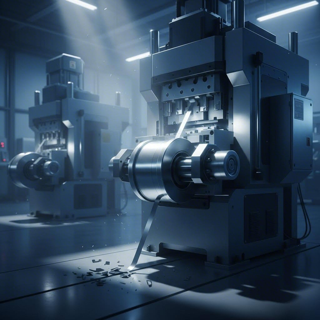
When you think about metal stamping operations, your mind probably jumps to the primary forming processes—blanking, piercing, bending, and drawing. But here's something many overlook: what happens to all that leftover material? This is where scrap cutters enter the picture, and their design can make or break your production efficiency.
So, what is metal stamping without proper waste management? It's an operation waiting for trouble. Scrap cutters are specialized cutting mechanisms integrated into progressive and transfer die operations specifically to segment, reduce, and evacuate waste material from the press area. Unlike the primary stamping dies that shape your finished parts, these components focus entirely on managing the carrier strip, skeleton scrap, and offal that remain after forming operations.
What Makes Scrap Cutters Essential in Stamping Operations
Understanding what is a stamping operation reveals why scrap management matters so much. During high-speed production, stamping dies generate continuous streams of waste material. Without properly designed cutters to manage this scrap, you'll face feeding problems, die damage, and unpredictable downtime.
Scrap cutter design for stamping involves engineering cutting mechanisms that can reliably process waste material at production speeds while maintaining synchronization with your press stroke. The design considerations include blade geometry, material selection, timing mechanisms, and integration with your existing automation systems.
What sets scrap cutters apart from primary die components? While stamping dies focus on forming precision parts, scrap cutters prioritize reliability and throughput. They must handle varying material thicknesses, maintain consistent cutting action across millions of cycles, and facilitate clean scrap evacuation without operator intervention.
Properly engineered scrap cutter design prevents up to 15% of unplanned press downtime by eliminating slug retention issues and ensuring smooth material flow through progressive dies.
The Hidden Cost of Poor Scrap Management
What is dies in manufacturing worth if they're constantly stopping due to scrap-related issues? The answer is far less than their potential. Poor scrap cutter design creates a cascade of problems that affect your entire operation.
Consider these common consequences of inadequate scrap management:
- Slug retention that damages finished parts and die surfaces
- Strip feeding errors from accumulated scrap blocking the die area
- Safety hazards from manual scrap removal during production
- Increased maintenance frequency on primary die components
- Reduced press speeds to compensate for unreliable scrap evacuation
The relationship between dies and stamping efficiency becomes clear when you analyze downtime causes. Many manufacturers discover that scrap-related issues account for a significant portion of their unplanned stops. Investing in proper scrap cutter engineering pays dividends through improved uptime and reduced maintenance costs.
Understanding these fundamentals sets the stage for exploring specific cutter types, blade geometries, and integration strategies that will transform how you approach this often-overlooked aspect of stamping die design.
Types of Scrap Cutters and Their Stamping Applications
Now that you understand why scrap cutters matter, let's explore the different types available and when each one makes sense. Choosing the right cutter type for your stamping die isn't a one-size-fits-all decision—it depends on your material, production speed, and specific application requirements.
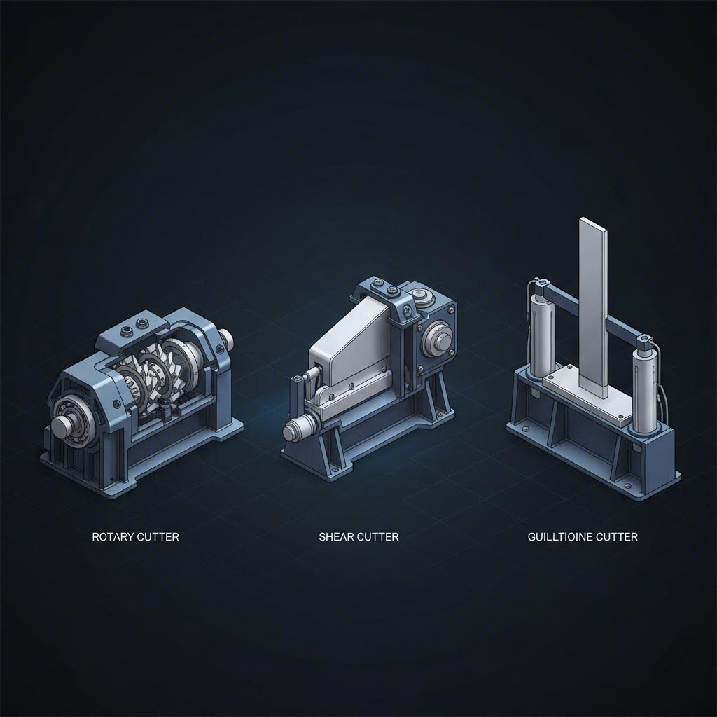
Three primary scrap cutter designs dominate the industry: rotary cutters, shear-type cutters, and guillotine designs. Each brings distinct advantages to different types of stamping dies and metal stamping dies configurations. Understanding their mechanisms and ideal applications helps you match the right technology to your production needs.
Rotary Scrap Cutters for High-Speed Applications
When you're running at maximum strokes per minute, rotary scrap cutters become your best friend. These systems use counter-rotating cylindrical blades that continuously shear scrap material as it exits the die for press operations. Imagine two synchronized rollers working together—one with cutting edges and one with corresponding grooves—creating a consistent cutting action without stopping.
What makes rotary stamping-integrated cutters ideal for high-speed work? Their continuous motion eliminates the acceleration and deceleration cycles that limit other designs. While a guillotine must stop, reverse, and restart for each cut, rotary systems maintain constant velocity. This translates directly into faster cycle times and reduced mechanical stress.
Key advantages of rotary scrap cutters include:
- Consistent cutting action at speeds exceeding 1,200 SPM
- Reduced vibration compared to reciprocating designs
- Adjustable chip length through speed synchronization
- Lower peak power requirements due to continuous cutting
- Quieter operation in high-volume production environments
However, rotary designs have limitations. They work best with thinner materials—typically under 2mm thickness—and require precise alignment between the rotating elements. The initial setup complexity is higher, and blade replacement involves more steps than simpler designs.
Shear vs Guillotine Designs for Heavy-Gauge Materials
When your stamping die processes heavier gauge materials, you'll likely choose between shear-type and guillotine cutters. Both use reciprocating motion, but their cutting mechanics differ significantly.
Shear-type cutters employ an angled blade that progressively engages the material, similar to how scissors work. This angular approach reduces peak cutting force requirements because only a portion of the blade contacts the scrap at any moment. For technical stamping applications involving materials over 3mm thick, this force reduction becomes critical for maintaining die longevity.
Guillotine designs, by contrast, use a straight blade that contacts the full scrap width simultaneously. This creates a cleaner cut edge but requires substantially higher instantaneous force. They excel in applications where cut quality matters—such as when scrap material will be recycled and uniformity affects handling.
Consider these factors when choosing between shear and guillotine designs:
- Material thickness: Shear types handle thicker materials with less force
- Cut quality requirements: Guillotines produce straighter edges
- Available press tonnage: Shear designs work better with limited force capacity
- Scrap handling: Guillotines create more uniform chip sizes
- Maintenance access: Guillotines typically offer simpler blade replacement
Comprehensive Scrap Cutter Comparison
Selecting the optimal scrap cutter for your metal stamping dies requires weighing multiple factors simultaneously. The following comparison table provides a side-by-side analysis to guide your decision:
| Criteria | Rotary Cutter | Shear-Type Cutter | Guillotine Cutter |
|---|---|---|---|
| Cutting Mechanism | Counter-rotating cylindrical blades with continuous cutting motion | Angled reciprocating blade with progressive engagement | Straight reciprocating blade with full-width contact |
| Ideal Material Thickness | 0.2mm – 2.0mm | 1.5mm – 6.0mm | 0.5mm – 4.0mm |
| Maximum SPM Capability | 1,200+ SPM | 400 – 800 SPM | 300 – 600 SPM |
| Maintenance Frequency | Moderate – blade regrinding every 500K-1M cycles | Low – blade replacement every 1M-2M cycles | Low to Moderate – blade replacement every 800K-1.5M cycles |
| Best-Fit Applications | High-speed progressive dies, thin gauge automotive parts, electronics components | Heavy gauge structural parts, thick steel stamping, transfer die operations | Medium gauge general stamping, applications requiring uniform scrap sizing |
| Relative Cost | Higher initial investment | Moderate | Lower initial cost |
| Setup Complexity | High – requires precise timing synchronization | Moderate – angle adjustment needed | Low – straightforward installation |
Notice how each cutter type occupies a distinct performance envelope. Rotary designs dominate high-speed, thin-material applications where every millisecond counts. Shear-type cutters handle the heavy lifting when thick materials demand force distribution. Guillotine systems offer simplicity and reliability for moderate-speed operations.
Your choice ultimately depends on matching cutter capabilities to your specific die for press requirements. A stamping die running automotive brackets at 1,000 SPM needs different scrap management than one forming heavy structural components at 200 SPM.
With the right cutter type selected, your next consideration becomes blade geometry—the cutting edge specifications that determine how cleanly and efficiently your scrap cutter performs its job.
Blade Geometry and Cutting Edge Specifications
You've selected your cutter type—now comes the engineering that truly separates reliable scrap cutters from problematic ones. Blade geometry might sound like a straightforward specification, but the angles, profiles, and clearances you choose directly impact cut quality, blade life, and overall stamping die design performance.
Think of blade geometry as the DNA of your scrap cutter. Every degree of rake angle and every thousandth of an inch in clearance creates ripple effects through your entire operation. Get these specifications right, and your cutter runs quietly for millions of cycles. Get them wrong, and you'll battle burrs, premature wear, and frustrating downtime.
Blade Angle Optimization for Clean Cuts
Why do angles matter so much in metal stamping die design? Consider what happens during each cut. The blade must penetrate the material, separate it cleanly, and release without dragging or tearing. Each phase demands specific geometric relationships between the cutting edge and workpiece.
The critical geometry parameters you need to understand include:
- Rake angle (5° to 15° positive): Controls how aggressively the blade bites into material. Higher rake angles reduce cutting force but weaken the edge. For softer materials like copper and aluminum, use 10° to 15°. For harder steels, stay between 5° and 10°.
- Relief angle (3° to 8°): Provides clearance behind the cutting edge to prevent rubbing. Insufficient relief causes friction heating and accelerated wear. More relief improves chip flow but reduces edge support.
- Land width (0.005" to 0.020"): The flat portion directly behind the cutting edge that provides structural support. Wider lands increase edge strength but require more cutting force.
- Edge radius (0.0005" to 0.002"): A slight radius strengthens the cutting edge against chipping. Sharper edges cut easier initially but dull faster. Match radius to material hardness.
Here's the engineering rationale behind these choices. When cutting soft materials like aluminum in the aluminum stamping process, you want aggressive geometry—higher rake angles and smaller edge radii. The material yields easily, so you can prioritize edge sharpness without risking premature failure.
Harder materials flip this logic. Steel stamping dies processing high-strength scrap need conservative geometry. Lower rake angles distribute cutting forces across more edge material. Larger edge radii prevent the micro-chipping that quickly degrades blade performance.
Clearance Calculations Based on Material Properties
If blade angles determine how your cutter attacks material, clearance determines how cleanly it separates. The gap between your cutting blade and the fixed die element—typically expressed as a percentage of material thickness—controls burr formation, cutting force requirements, and edge quality.
Sounds complex? It becomes intuitive once you understand the underlying mechanics. During cutting, material initially deforms elastically, then plastically, before fracturing. Proper clearance ensures the fracture zones from upper and lower cutting edges meet cleanly within the material thickness.
Clearance guidelines based on material type:
- Soft copper and brass: 3% to 5% of material thickness
- Aluminum alloys: 4% to 6% of material thickness
- Mild steel and iron: 5% to 8% of material thickness
- Stainless steel: 6% to 10% of material thickness
- High-strength steel: 8% to 12% of material thickness
Why do harder materials need more clearance? Their higher strength means greater elastic recovery after initial deformation. Tighter clearances force the blade to work against this spring-back, increasing cutting forces and accelerating wear. Additionally, harder materials generate more heat during cutting—extra clearance improves chip evacuation and reduces thermal buildup.
For sheet metal stamping dies handling multiple materials, consider designing for your hardest material and accepting slightly larger burrs on softer ones. Alternatively, some advanced metal stamping techniques incorporate adjustable clearance mechanisms for quick changeover between material grades.
Material hardness also influences your blade geometry selections in interconnected ways. A stainless steel scrap cutter needs both conservative blade angles and generous clearances. Attempting to compensate for tight clearance with aggressive rake angles—or vice versa—typically creates new problems rather than solving existing ones.
Understanding these geometric relationships transforms stamping die design from guesswork into engineering. With your blade geometry specified, the next critical decision involves selecting materials and heat treatments that maintain these precise specifications across millions of production cycles.
Material Selection and Heat Treatment Requirements
You've nailed down your blade geometry—but even perfect angles mean nothing if your blade material can't hold those specifications under production stress. Material selection for scrap cutter components determines whether your carefully engineered geometry survives 100,000 cycles or 10 million. This decision impacts everything from maintenance schedules to total cost of ownership in your metal stamping tooling investment.
When evaluating materials for die stamping applications, you're balancing competing demands. Hard materials resist wear but may chip under impact. Tough materials absorb shock but dull faster. Understanding these tradeoffs helps you match blade materials to your specific production requirements.
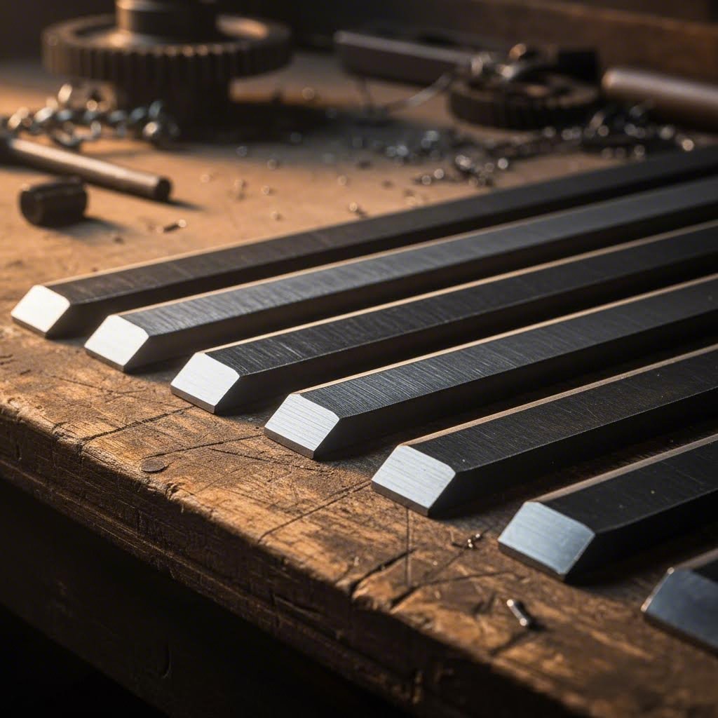
Tool Steel Selection for Scrap Cutter Blades
Not all tool steels perform equally in scrap cutter applications. The demands of continuous cutting in metal parts stamping environments require specific material characteristics. Here are the primary tool steel grades you'll encounter and their performance profiles:
D2 Tool Steel remains the workhorse choice for many die stamp applications. With 11-13% chromium content, it offers excellent wear resistance and reasonable toughness. D2 achieves working hardness of 58-62 HRC and maintains sharp edges well in moderate-speed applications. Its main limitation? Reduced impact resistance compared to lower-alloy options.
A2 Tool Steel provides a balanced alternative when toughness matters more than maximum wear resistance. Air-hardening properties simplify heat treatment, and the material handles interrupted cuts without chipping. A2 works particularly well in sheet metal dies processing thicker materials where cutting forces create significant impact loads.
M2 High-Speed Steel excels in high-temperature applications where friction heating becomes a concern. Its tungsten and molybdenum content maintains hardness at elevated temperatures—a critical advantage in high-speed rotary cutter applications running above 800 SPM.
Powder Metallurgy (PM) Grades like CPM 10V and Vanadis 4E represent premium options for demanding applications. Their fine, uniform carbide structure delivers exceptional wear resistance while maintaining better toughness than conventional tool steels. The cost premium—often 3-5 times conventional grades—pays off in extended blade life and reduced changeover frequency.
When selecting your blade material, evaluate these key factors:
- Wear resistance: How well does the material maintain sharp edges against abrasive scrap? Higher carbide content improves abrasion resistance.
- Toughness: Can the material absorb impact without chipping or fracturing? Critical for heavy-gauge materials and interrupted cuts.
- Machinability: How easily can you grind and resharpen blades? Harder grades require specialized grinding equipment.
- Cost considerations: Balance initial material cost against expected blade life and maintenance labor.
- Heat treatment response: Does the material achieve consistent hardness with predictable distortion?
Heat Treatment Protocols for Maximum Durability
Even premium tool steel performs poorly without proper heat treatment. The heating, quenching, and tempering sequence transforms raw steel into a blade capable of withstanding millions of cutting cycles in metal stamping tooling applications.
Proper heat treatment achieves three critical objectives. First, it develops maximum hardness in the cutting edge zone. Second, it creates appropriate toughness in the blade body. Third, it relieves internal stresses that could cause cracking or distortion during use.
For D2 tool steel—the most common scrap cutter blade material—a typical protocol includes:
- Preheat to 1200°F to equalize temperature throughout the blade
- Austenitize at 1850°F for sufficient time to dissolve carbides
- Air quench or oil quench based on section thickness
- Double temper at 400-500°F to achieve 60-62 HRC final hardness
- Cryogenic treatment (optional) to convert retained austenite
Surface treatments further extend blade life in demanding environments. Titanium nitride (TiN) coatings reduce friction and provide a hard surface layer. Titanium carbonitride (TiCN) offers improved wear resistance for cutting abrasive materials. Diamond-like carbon (DLC) coatings excel in aluminum applications where material adhesion causes problems.
What blade life can you expect with proper material selection and heat treatment? Conservative estimates suggest 500,000 to 1 million cuts for standard D2 blades in mild steel applications. PM grades with advanced coatings regularly achieve 2-3 million cycles before requiring resharpening. These numbers translate directly into reduced maintenance intervals and lower per-part tooling costs.
With materials and heat treatment specified, you're ready to tackle the complete design methodology—transforming these component decisions into a functioning scrap cutter system.
Step-by-Step Scrap Cutter Design Methodology
You've selected your cutter type, optimized blade geometry, and specified materials—but how do you bring all these decisions together into a functioning system? A systematic design methodology transforms individual component choices into an integrated scrap cutter that performs reliably across millions of cycles in your metal stamping process.
Many engineers approach scrap cutter design reactively, solving problems as they emerge during production. This section flips that approach, walking you through a proactive methodology that anticipates issues before they become expensive production problems.
From Requirements to Conceptual Design
Every successful scrap cutter project starts with clearly defined requirements. Sounds obvious? You'd be surprised how many designs fail because engineers jumped straight into CAD without establishing fundamental parameters. The stamping process in manufacturing demands precision at every stage—and that begins with understanding exactly what your cutter must accomplish.
Follow this sequential design process to move from initial concept to production-ready specifications:
- Define operational requirements: Document your target production speed (SPM), material specifications (type, thickness, width), scrap strip dimensions, and desired chip length. Capture the full operating envelope including minimum and maximum conditions.
- Analyze integration constraints: Measure available space within or adjacent to your stamping die. Identify mounting interfaces, available power sources (pneumatic, hydraulic, mechanical cam), and control system compatibility requirements.
- Calculate cutting force requirements: Using the formula F = S × t × L × k (where S = material shear strength, t = thickness, L = cut length, and k = correction factor typically 1.1-1.3), determine the peak force your cutter mechanism must generate.
- Select drive mechanism: Match your force requirements and cycle rate to appropriate actuation. Mechanical cams suit high-speed applications synchronized with press motion. Pneumatic cylinders offer flexibility for retrofit installations. Hydraulic systems handle heavy-gauge cutting where force demands exceed pneumatic capabilities.
- Develop conceptual layouts: Sketch multiple design approaches that satisfy your requirements. Consider rotary, shear, and guillotine configurations against your specific constraints. Evaluate each concept against manufacturability, maintainability, and cost criteria.
- Perform preliminary sizing: Based on cutting forces, determine blade dimensions, support structures, and actuator specifications. Account for safety factors—typically 1.5 to 2.0 for production tooling exposed to dynamic loads.
During requirements gathering, pay special attention to edge cases. What happens when material thickness varies at specification limits? How does your cutter respond to double-thick splices? The stamping metal process often presents unexpected conditions—your design must handle them gracefully.
For drive mechanism selection, consider the relationship between force, speed, and precision. Mechanical cam drives offer the tightest timing synchronization but require careful design to handle varying loads. Pneumatic systems provide excellent force-to-weight ratios but introduce timing variability from air compressibility. Match your mechanism to your tolerance for cycle-to-cycle variation.
Engineering Validation Before Production
Conceptual design gets you started—but detailed engineering and validation determine whether your scrap cutter performs as intended. This phase transforms sketches into manufacturing drawings while identifying potential failure modes before they manifest in production.
Modern CAE simulation tools revolutionize how engineers validate scrap cutter designs. Rather than building physical prototypes and discovering problems through trial and error, simulation predicts performance virtually. This approach dramatically reduces development time and cost in manufacturing stamping process applications.
Key simulation analyses for scrap cutter validation include:
- Finite Element Analysis (FEA): Model stress distribution through blades and support structures under cutting loads. Identify stress concentrations that could initiate fatigue cracks. Verify that deflections remain within acceptable limits for maintaining cutting clearances.
- Dynamic simulation: Analyze mechanism motion through complete cutting cycles. Verify timing relationships between cutter action and press stroke. Identify potential interference conditions or timing conflicts.
- Cutting process simulation: Advanced software models material deformation during shearing. Predict burr formation, cutting force profiles, and chip behavior. These insights help optimize blade geometry before physical testing.
Beyond simulation, your validation phase should include:
- Design review: Gather input from manufacturing, maintenance, and operations personnel. Their practical experience often identifies issues that simulation misses.
- Prototype testing: Build initial units for controlled testing outside production. Verify cutting performance across the full material specification range.
- Integration testing: Install prototypes in actual press lines during non-production periods. Confirm timing synchronization and automation compatibility under real conditions.
- Production validation: Run extended trials at production speeds while monitoring key performance indicators. Document any issues for design refinement.
The die processing methodology you follow during development directly impacts long-term reliability. Rushing through validation to meet production deadlines often creates problems that persist for years. Invest the time upfront to verify your design thoroughly.
What makes CAE simulation particularly valuable for scrap cutter design? You can test dozens of geometry variations in hours rather than weeks. When calculating cutting forces suggests you're near capacity limits, simulation reveals exactly where problems will emerge—before you've committed to expensive tooling.
With your design validated through simulation and prototype testing, the next challenge becomes integrating your scrap cutter seamlessly into existing press lines and automation systems.
Integration with Stamping Press Lines and Automation
Your scrap cutter design looks perfect on paper—but how does it perform when connected to a real die stamping machine running at full production speed? Integration challenges often surprise engineers who focused exclusively on cutting mechanics. The interface between your scrap cutter and existing press line equipment determines whether your carefully engineered system delivers its promised performance.
Think about what happens during each press cycle. Your stamping tool and die components must work in precise coordination—the strip feeds, the press closes, forming operations complete, and scrap must evacuate before the next cycle begins. Your cutter must execute its function within a narrow timing window, every single time, without fail.
Synchronizing Cutter Timing with Press Operations
Timing synchronization represents the most critical integration challenge for scrap cutter installations. A cutter that fires too early catches material still under tension from the forming operation. Fire too late, and you'll miss your window before the next strip advance begins.
How do you achieve reliable synchronization? The approach depends on your die-stamping machine configuration and production speed requirements. Mechanical cam drives offer the tightest synchronization—they're physically linked to press motion, eliminating timing drift entirely. However, they require significant engineering effort to retrofit into existing installations.
Electronic synchronization provides flexibility for retrofit applications. A resolver or encoder mounted on the press crankshaft generates position signals that trigger cutter actuation at precisely defined stroke angles. Modern controllers can compensate for actuator response delays, adjusting trigger timing based on actual press speed.
Consider these timing-related factors when planning your integration:
- Actuation delay: Pneumatic cylinders require 20-50ms to develop full force. Account for this lag in your trigger timing.
- Speed variation: Production speeds often vary. Your timing system must adjust trigger points automatically as SPM changes.
- Die protection: Build in timing verification that prevents press cycling if the cutter fails to complete its stroke.
- Diagnostic capability: Log timing data for troubleshooting. Small timing drifts often precede major failures.
For stamping manufacturing environments running multiple die configurations, consider programmable timing systems. Store optimal timing parameters for each setup and recall them during changeover. This eliminates time-consuming manual adjustments and ensures consistent performance across product variations.
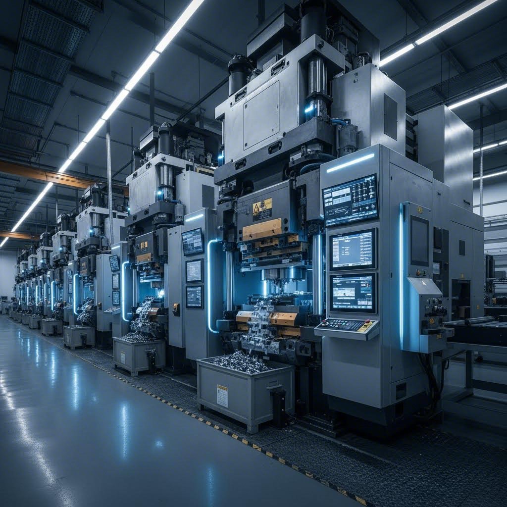
Automation Integration for Continuous Production
Modern press lines rely on extensive automation for continuous operation. Your scrap cutter must communicate with supervisory systems, respond to fault conditions, and integrate with material handling equipment. Treating the cutter as an isolated component rather than part of an interconnected system creates integration headaches.
Sensor integration enables intelligent scrap management. Photoelectric sensors detect scrap presence before and after cutting, verifying successful operation. Proximity sensors confirm blade position, catching mechanical failures before they cause damage. Force monitoring identifies dulling blades that need sharpening—addressing problems during planned maintenance rather than unplanned downtime.
When retrofitting scrap cutters into existing lines, work through this critical integration checklist:
- Electrical connections: Verify available voltage and current capacity. Confirm compatibility with existing control system I/O modules. Plan cable routing that avoids interference with moving components.
- Pneumatic/hydraulic requirements: Assess available air pressure and flow capacity. Size supply lines to prevent pressure drops during rapid actuation. Install filtration to protect precision components.
- Control system compatibility: Confirm communication protocol support (discrete I/O, fieldbus, Ethernet). Program interlocks with press control and feed systems. Integrate fault signals with line supervisory systems.
- Safety compliance: Meet applicable machine safety standards. Install guards that prevent access during operation. Implement lockout provisions for maintenance access. Verify emergency stop integration.
Safety interlock requirements deserve special attention. Die in manufacturing environments present serious hazards, and scrap cutters add another potential injury source. Your integration must ensure the cutter cannot operate when guards are open, maintenance personnel are present, or fault conditions exist.
Proper integration impacts overall stamping line efficiency in ways that extend beyond the cutter itself. A well-integrated system enables higher production speeds by eliminating timing uncertainties. It reduces scrap-related downtime through predictive monitoring. It simplifies troubleshooting by providing clear diagnostic information when problems occur.
What happens when integration falls short? You'll see intermittent failures that frustrate operators and maintenance technicians alike. Timing drift causes occasional misfires that damage dies or create jams. Communication failures leave supervisory systems blind to developing problems. These issues often trace back to shortcuts taken during initial installation—shortcuts that seemed harmless but created ongoing headaches.
Even with perfect integration, problems occasionally arise during production. The next section addresses troubleshooting strategies that help you diagnose and resolve common scrap cutter issues quickly.
Troubleshooting Common Scrap Cutter Problems
Your scrap cutter ran flawlessly for weeks—then suddenly, problems appear. Slugs stick in the die. Blades chip unexpectedly. Timing drifts just enough to cause intermittent failures. Sound familiar? Troubleshooting these issues effectively requires understanding the root causes behind each symptom, not just treating surface-level effects.
Many stamped parts manufacturers lose significant production time chasing symptoms rather than solving underlying problems. This section equips you with diagnostic approaches that identify true root causes and corrective actions that prevent recurrence. Whether you're dealing with slug retention in your stamp die or premature blade failure, you'll find practical guidance here.
Preventing Slug Retention Through Design
Slug retention—when cut scrap pieces stick in the die rather than ejecting cleanly—ranks among the most frustrating problems in metal stamped parts production. A retained slug can damage the next part, score die surfaces, or jam the entire operation. Prevention starts with understanding why slugs stick in the first place.
Several factors contribute to slug retention:
- Insufficient clearance: Tight clearances create friction that holds slugs in the cutting cavity. Review your clearance calculations against actual material thickness.
- Vacuum effect: Rapid blade withdrawal creates negative pressure beneath the slug, sucking it back into the die opening.
- Oil film adhesion: Stamping lubricants sometimes create surface tension that bonds slugs to die surfaces.
- Magnetic attraction: Steel slugs can magnetize during cutting, clinging to die stamps and tooling components.
- Burr interference: Excessive burrs catch on die walls, preventing clean ejection.
Design-based solutions address these issues proactively. Spring-loaded ejector pins provide positive force to push slugs clear of the cutting zone. Angled slug relief channels direct cut pieces away from the die opening. Air blast systems timed to blade withdrawal overcome vacuum effects. For magnetic materials, demagnetizing units mounted near the cutter neutralize residual magnetism.
What about bypass notches in sheet metal stamping dies? These small relief cuts in the die edge serve a specific purpose—they break the vacuum seal that forms during cutting. The purpose of bypass notches in stamping dies becomes clear when you understand slug retention mechanics: by allowing air to flow behind the slug during blade withdrawal, they eliminate the suction effect that pulls cut pieces back into the die.
When troubleshooting existing slug retention problems, start by examining retained slugs carefully. Scratch patterns reveal interference points. Deformation indicates clearance issues. Oil residue suggests adhesion problems. This forensic approach identifies which retention mechanism you're fighting.
Diagnosing Blade Wear Patterns
Blade wear tells a story—if you know how to read it. Different wear patterns indicate different problems, and understanding these patterns helps you address root causes rather than simply replacing blades repeatedly.
Normal wear appears as uniform dulling along the cutting edge. The edge radius gradually increases, cutting forces rise predictably, and burr size grows proportionally. This wear pattern indicates your blade material, geometry, and operating conditions are reasonably matched. Schedule resharpening based on observed burr growth or force monitoring data.
Abnormal wear patterns demand investigation:
- Edge chipping: Small chips or fractures along the cutting edge indicate excessive impact loading, insufficient toughness, or improper heat treatment. Consider tougher blade materials or reduced rake angles.
- Localized wear: Accelerated wear in specific areas suggests misalignment, uneven material thickness, or debris accumulation. Check blade-to-die alignment and material specifications.
- Cratering: Wear concentrated on the rake face (behind the cutting edge) indicates excessive friction heating. Improve lubrication or reduce cutting speed.
- Built-up edge: Material adhesion to the blade surface suggests chemical affinity between blade and workpiece. Apply appropriate coatings or change blade material.
- Catastrophic fracture: Complete blade failure indicates severe overload, material defects, or fatigue. Review cutting force calculations and inspect for stress concentrators.
For die stamps processing multiple material types, track wear patterns by material. You may discover that certain alloys cause disproportionate wear, justifying dedicated blades for problematic materials or adjusted maintenance schedules.
Common Failure Symptoms and Solutions
When problems arise during production, rapid diagnosis saves valuable time. The following table maps common symptoms to their likely causes and recommended corrective actions:
| Symptom | Likely Root Cause | Recommended Solution |
|---|---|---|
| Slugs stick in die opening | Insufficient clearance, vacuum effect, or oil adhesion | Increase clearance 5-10%, add ejector pins, install air blast, or apply dry lubricant |
| Excessive burr on cut edge | Dull blade, excessive clearance, or improper blade geometry | Resharpen or replace blade, verify clearance specifications, adjust rake angle |
| Blade chips or fractures | Impact overload, insufficient toughness, or improper heat treatment | Switch to tougher blade material, reduce rake angle, verify heat treatment hardness |
| Intermittent timing failures | Actuator response drift, encoder issues, or mechanical looseness | Recalibrate timing, inspect position sensors, tighten mechanical connections |
| Inconsistent chip length | Feed timing variation, strip tension changes, or cutter speed drift | Verify feed synchronization, adjust strip tensioner, check cutter drive system |
| Unusual noise during cutting | Blade-to-die contact, debris in mechanism, or bearing failure | Check blade alignment and clearance, clean mechanism, inspect bearings |
| Rapid blade dulling | Insufficient hardness, abrasive material, or inadequate lubrication | Upgrade blade material grade, apply wear-resistant coating, improve lubrication |
| Material jamming before cutter | Timing mismatch, scrap accumulation, or guide misalignment | Adjust timing, improve scrap evacuation, realign material guides |
| Actuator fails to complete stroke | Low air/hydraulic pressure, valve malfunction, or mechanical binding | Check supply pressure, inspect valve operation, lubricate mechanism |
Establishing Preventive Maintenance Schedules
Reactive maintenance—fixing things after they break—costs far more than preventing problems in the first place. Establishing appropriate preventive maintenance intervals keeps your scrap cutter running reliably while minimizing unnecessary service stops.
Your maintenance schedule should reflect both production volume and material characteristics. High-speed operations processing abrasive materials need more frequent attention than low-volume applications cutting soft metals. Consider these baseline intervals as starting points, then adjust based on your observed wear rates:
- Daily: Visual inspection for debris accumulation, unusual wear, or damage. Verify proper lubrication. Check scrap evacuation system function.
- Weekly: Clean mechanism thoroughly. Inspect blade edges for chipping or unusual wear. Verify timing calibration. Check actuator response.
- Monthly: Measure blade edge condition and compare to baseline. Inspect mounting hardware for looseness. Test sensor operation. Review diagnostic logs for developing trends.
- Quarterly: Complete mechanical inspection including bearings, guides, and actuators. Assess blade life remaining and schedule replacement if needed. Verify safety interlock function.
Material characteristics significantly influence maintenance requirements. Stainless steel and high-strength alloys accelerate blade wear—plan for 2-3 times more frequent blade service compared to mild steel. Aluminum creates adhesion problems that require regular cleaning. Coated materials may introduce abrasive particles that accumulate in the mechanism.
Document everything. Maintenance logs reveal patterns invisible in day-to-day operations. Gradually decreasing blade life might indicate process drift. Recurring timing problems could signal controller degradation. This historical data transforms reactive troubleshooting into predictive maintenance.
Effective troubleshooting and preventive maintenance keep your scrap cutter performing reliably—but these operational considerations connect directly to broader economic impacts. Understanding the full cost picture helps justify investments in quality design and proper maintenance programs.
Cost Optimization Through Smart Scrap Cutter Design
You've invested in blade geometry, selected premium materials, and integrated your cutter flawlessly with the press line. But here's the question that matters most to decision-makers: what's the return on that investment? Understanding how scrap cutter design decisions ripple through your entire metal stamping operation reveals why cutting corners on cutter engineering ultimately costs more than doing it right.
Too often, manufacturers evaluate scrap cutters based solely on purchase price. This narrow view misses the larger picture. A cheaper cutter that causes one hour of unplanned downtime per week costs far more than a premium system that runs trouble-free for months. Let's break down the true economics of scrap cutter performance.
Calculating True Cost of Scrap Cutter Performance
What does poor scrap cutter performance actually cost? Start with the numbers that matter most—press downtime. In sheet metal stamping operations, every minute of unplanned stoppage carries significant financial weight. Between lost production, operator idle time, and recovery efforts, even brief interruptions add up quickly.
Consider a typical stamping line running at 600 SPM producing automotive brackets. If scrap-related issues cause just 15 minutes of downtime daily, that translates to roughly 9,000 lost parts per day. Across a year of production, those seemingly minor stoppages eliminate over 2 million potential parts. Now multiply by your per-part margin—the economic impact becomes substantial.
But downtime represents only part of the equation. Metal stamping manufacturing economics involve multiple cost factors that connect directly to scrap cutter design quality:
- Press uptime: Well-designed cutters eliminate the majority of scrap-related stoppages. Each percentage point of improved uptime translates directly to increased output without additional capital investment.
- Material utilization: Proper scrap segmentation enables cleaner evacuation and reduces instances where retained slugs damage finished parts. Fewer rejected parts means better material yield.
- Labor costs: Manual scrap clearing, frequent blade changes, and troubleshooting consume operator and maintenance technician time. Reliable cutters free these resources for value-adding activities.
- Die maintenance: Slug retention and scrap interference damage primary die components. Preventing these issues extends die life and reduces rework costs.
- Energy consumption: Dull blades require more cutting force, increasing power draw. Well-maintained, properly designed cutters operate more efficiently.
- Scrap value recovery: Uniformly sized chips command better prices from recyclers. Mangled, inconsistent scrap often receives lower valuations.
When you tally these factors, the true cost difference between adequate and excellent scrap cutter design often spans tens of thousands of dollars annually for a single press line. For operations running multiple stamping presses, the cumulative impact multiplies accordingly.
Design Decisions That Impact Production Economics
Now that you understand the cost categories, let's connect specific design decisions to their economic outcomes. Every choice you make during scrap cutter development affects your bottom line—some in obvious ways, others less apparent.
Blade material selection offers a clear example. Choosing standard D2 tool steel over premium PM grades might save $500-$1,000 per blade set. But if the premium material doubles blade life from 500,000 to 1,000,000 cycles, you've eliminated an entire blade change—plus the associated downtime, labor, and production disruption. The math usually favors quality.
Geometry optimization plays a similar role. Investing engineering time to dial in optimal rake angles, clearances, and edge preparations for your specific materials yields returns across millions of cycles. A 10% reduction in cutting force extends blade life, reduces actuator wear, and lowers energy consumption. These incremental improvements compound over time.
Integration quality affects economics through reliability. Precise timing synchronization prevents the intermittent failures that frustrate operators and waste troubleshooting time. Proper sensor integration enables predictive maintenance—addressing blade wear during planned downtime rather than unplanned emergencies.
What about the cost of engineering support during design? Here's where partnerships with experienced tooling providers deliver measurable value. Advanced CAE simulation capabilities, like those offered by certified die manufacturers, catch design issues before physical prototyping. This simulation-first approach reduces costly iteration cycles and accelerates time to production. Manufacturers like Shaoyi, with IATF 16949 certification and proven first-pass approval rates exceeding 93%, demonstrate how proper engineering investment translates to faster, more reliable results.
The metal stamping and forming industry increasingly recognizes that total cost of ownership—not purchase price—determines true equipment value. When evaluating scrap cutter options, consider these factors beyond initial investment:
- Expected blade life: Calculate cost per cut, not cost per blade. Longer-lasting blades often deliver better economics despite higher unit prices.
- Maintenance requirements: Systems designed for quick blade access reduce changeover time. Every minute saved during maintenance is a minute of potential production.
- Spare parts availability: Proprietary components with long lead times create vulnerability. Standard parts and responsive suppliers minimize disruption risk.
- Technical support: Access to engineering expertise for optimization and troubleshooting adds ongoing value beyond the initial purchase.
- Upgrade path: Can the system adapt to future requirements? Modular designs accommodate changing production needs without complete replacement.
Stamped sheet metal production succeeds when every element of the operation works harmoniously. Scrap cutters might seem like minor components compared to the primary forming dies, but their impact on overall economics is anything but minor. The manufacturers who recognize this—and invest accordingly—consistently outperform competitors who treat scrap management as an afterthought.
Understanding these economic realities sets the stage for making informed decisions about your scrap cutter projects. Whether you design in-house or partner with specialized providers, the principles remain the same: invest in quality where it matters, and the returns will follow.
Putting Scrap Cutter Design Principles Into Practice
You've journeyed through blade geometry, material selection, integration challenges, and economic analysis. Now comes the practical question: how do you translate this knowledge into successful scrap cutter projects? Whether you're designing your first cutter or optimizing existing systems, synthesizing these principles into actionable steps separates successful implementations from frustrating failures.
What is stamping excellence without attention to every component—including scrap management? The manufacturers who consistently deliver high-quality die stamped parts understand that scrap cutter performance directly impacts their competitive position. Let's consolidate the critical success factors and help you determine the best path forward for your specific situation.
Critical Success Factors for Your Scrap Cutter Project
After covering all aspects of scrap cutter engineering, certain themes emerge as non-negotiable for success. These factors separate reliable systems from those that create ongoing production headaches. Before launching your next project, verify that your approach addresses each of these fundamentals.
Use this comprehensive checklist as your scrap cutter design reference:
- Match cutter type to application: Select rotary, shear, or guillotine designs based on your material thickness, production speed, and space constraints—not just initial cost.
- Optimize blade geometry for your materials: Calculate proper rake angles, relief angles, and clearances based on specific material properties. One-size-fits-all geometry leads to compromised performance.
- Invest in appropriate blade materials: Balance wear resistance, toughness, and cost based on expected production volumes. Premium PM grades often deliver better economics despite higher unit prices.
- Specify proper heat treatment: Ensure blade suppliers follow documented protocols. Request hardness certification and consider cryogenic treatment for demanding applications.
- Design for integration from the start: Account for timing synchronization, sensor requirements, and safety interlocks during initial design—not as afterthoughts.
- Plan for maintenance access: Quick blade changes minimize downtime. Design mechanisms that allow service without major disassembly.
- Incorporate diagnostic capabilities: Force monitoring, timing verification, and scrap detection sensors enable predictive maintenance and rapid troubleshooting.
- Document everything: Capture design rationale, operating parameters, and maintenance procedures. This documentation proves invaluable when personnel change or problems arise.
What is stamped metal quality worth if scrap-related issues compromise your production? Each checklist item represents lessons learned—often painfully—across countless stamping die manufacturing projects. Skipping any element creates risk that compounds over millions of production cycles.
Making the Build vs Partner Decision
Here's a question many engineers face: should you design scrap cutters in-house or partner with specialized tooling providers? The answer depends on your internal capabilities, project timeline, and long-term support requirements.
In-house design makes sense when you have:
- Experienced tool designers familiar with your specific materials and processes
- Adequate engineering time without impacting other critical projects
- Manufacturing capabilities to produce precision components
- Flexibility to iterate through development without production pressure
Partnering with specialized providers becomes advantageous when:
- Timeline pressure demands rapid development—sometimes as little as 5 days for prototyping
- Your application requires expertise beyond current team capabilities
- Quality certifications like IATF 16949 are mandatory for your automotive stamping die projects
- You need CAE simulation capabilities to validate designs before committing to tooling
- First-pass success is critical to meeting production schedules
The die and stamping industry offers various partnership models. Some providers focus purely on component supply, while others offer comprehensive engineering support from concept through production validation. Manufacturers like Shaoyi exemplify the full-service approach, combining rapid prototyping capabilities with advanced simulation and OEM-standard quality systems. Their 93% first-pass approval rate demonstrates how experienced partners reduce the iteration cycles that delay production launches.
Consider the total cost of each approach—not just direct engineering hours. In-house development carries hidden costs: learning curve time, prototype iterations, and opportunity cost of delayed production. Professional stamping die manufacturing partners amortize these development costs across many projects, often delivering solutions faster and more economically than internal teams building expertise from scratch.
Whichever path you choose, the principles covered throughout this article remain your foundation. Proper geometry optimization, material selection, integration planning, and economic analysis apply whether you're designing at your own workstation or collaborating with external experts.
Your scrap cutter project begins with understanding what success looks like—reliable performance across millions of cycles, minimal maintenance intervention, and seamless integration with your stamping operation. Armed with the knowledge from this guide, you're equipped to achieve exactly that.
Frequently Asked Questions About Scrap Cutter Design for Stamping
1. What is a scrap cutter in stamping operations?
A scrap cutter is a specialized cutting mechanism integrated into progressive and transfer die operations to segment, reduce, and evacuate waste material from the press area. Unlike primary stamping dies that shape finished parts, scrap cutters focus on managing carrier strips, skeleton scrap, and offal remaining after forming operations. Properly designed scrap cutters prevent up to 15% of unplanned press downtime by eliminating slug retention issues and ensuring smooth material flow.
2. What are the main types of scrap cutters used in metal stamping?
Three primary scrap cutter designs dominate the industry: rotary cutters, shear-type cutters, and guillotine designs. Rotary cutters use counter-rotating cylindrical blades for high-speed applications exceeding 1,200 SPM with thin materials. Shear-type cutters employ angled blades for heavy-gauge materials up to 6mm thick. Guillotine cutters offer straightforward installation with full-width cutting for medium-gauge applications requiring uniform scrap sizing.
3. How do you calculate proper blade clearance for scrap cutters?
Blade clearance is typically expressed as a percentage of material thickness and varies by material type. For soft copper and brass, use 3-5% clearance. Aluminum alloys require 4-6%, mild steel needs 5-8%, stainless steel requires 6-10%, and high-strength steel demands 8-12% clearance. Harder materials need more clearance because their higher strength causes greater elastic recovery after deformation.
4. What tool steel grades are best for scrap cutter blades?
D2 tool steel remains the workhorse choice with 11-13% chromium content offering excellent wear resistance at 58-62 HRC hardness. A2 tool steel provides better toughness for thicker materials. M2 high-speed steel excels in high-temperature applications above 800 SPM. Premium powder metallurgy grades like CPM 10V deliver exceptional wear resistance with better toughness, often lasting 2-3 million cycles before resharpening.
5. How can I prevent slug retention in scrap cutter operations?
Slug retention occurs due to insufficient clearance, vacuum effects, oil film adhesion, magnetic attraction, or burr interference. Design-based solutions include spring-loaded ejector pins for positive ejection force, angled slug relief channels, air blast systems timed to blade withdrawal, and bypass notches that break vacuum seals. For steel materials, demagnetizing units neutralize residual magnetism. Certified die manufacturers like Shaoyi use CAE simulation to optimize designs and achieve 93% first-pass approval rates.