 دُفعات صغيرة، معايير عالية. خدمتنا لتطوير النماذج الأولية بسرعة تجعل التحقق أسرع وأسهل —

شرح خدمات التشغيل الآلي: من المعدن الخام إلى الأجزاء الدقيقة
ما المقصود فعليًّا بخدمات التشغيل الآلي في التصنيع الحديث
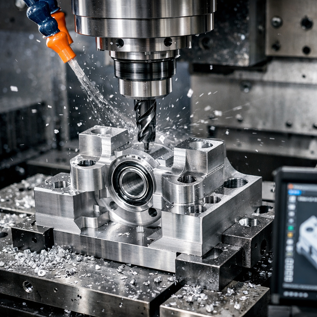
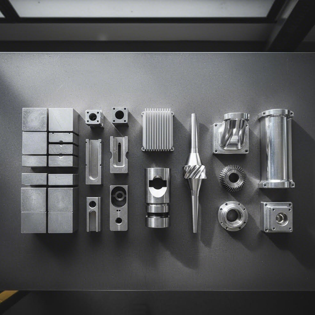
تصوَّر أنك تبدأ بكتلة صلبة من الألومنيوم وتنتهي بمكوِّنٍ جويٍّ فضائيٍّ مُشكَّل بدقة تامة ، بدقة تصل إلى عرض شعرة بشرية. هذه هي القوة التي يمتلكها التشغيل الآلي الحديث في العمل. سواء كنت مهندسًا تبحث عن قطع غيار أو مالك شركة تستكشف خيارات التصنيع، فإن فهم هذه العملية يفتح الباب أمام اتخاذ قرارات أكثر ذكاءً وتحقيق منتجات أفضل.
تستخدم خدمات التشغيل الآلي الدقيق آلات خاضعة للتحكم الحاسوبي لإزالة المادة من الكتل الصلبة، مما يُنتج مكونات تتميَّز بتسامحات دقيقة للغاية — غالبًا ضمن حدود ٠٫٠٠٥ بوصة أو أقل — وتلبّي المواصفات التصميمية المحددة بدقة.
من المادة الخام إلى الجزء الدقيق
في جوهرها، تحوّل خدمة التشغيل الآلي المواد الأولية إلى مكونات نهائية من خلال إزالة مُحكَمة للمواد. ويبدأ هذا العملية بقطعة أولية — وهي عبارة عن كتلة أو قضيب أو أسطوانة من المعدن أو البلاستيك — ثم تُزال منها بشكل منهجي كل الأجزاء غير الضرورية في التصميم النهائي. ويمكنك أن تتصور الأمر على أنه نحتٌ، لكن بدقة موجهة بواسطة الحاسوب بدلًا من النحت اليدوي بالمنقاش.
وتُعرف هذه الطريقة باسم التصنيع الطردي، وهي تختلف تمامًا عن الطرق التجميعية مثل الطباعة ثلاثية الأبعاد، حيث تُبنى القطع طبقةً تلو الأخرى. ولا يزال تشغيل المعادن عبر العمليات الطرفية يُعتبر المعيار الذهبي عند الحاجة إلى مكونات قادرة على تحمل الإجهادات الواقعية والحرارة والاستخدام المتكرر.
الميزة التنافسية للتصنيع الطردي
لماذا يتفوّق إزالة المادة على إضافتها في العديد من التطبيقات؟ تكمن الإجابة في سلامة المادة. فعند تشغيل جزء ما من بلوك صلب، فإنك تعمل على مادة تمتلك خصائص داخلية متجانسة طوال حجمها. فلا توجد خطوط طبقات، ولا نقاط ضعف بين الطبقات المُترسَّبة، ولا توجد مخاوف تتعلق بالمسامية الداخلية.
وهذا أمرٌ في غاية الأهمية بالنسبة إلى:
- العناصر الهيكلية الأجزاء التي يجب أن تحمِل أحمالاً دون أن تفشل
- الأجزاء المتحركة المتطلبة لأسطح ناعمة وملاءمة دقيقة
- تطبيقات درجات الحرارة العالية حيث تمنع اتساق المادة التقوُّس
- الأجزاء الطبية والفضائية حيث تكون هامش السلامة غير قابل للتفاوض
والنتيجة؟ إن التشغيل الدقيق باستخدام الحاسب الآلي (CNC) يُنتج أجزاء يمكن الاعتماد عليها في التطبيقات الحرجة، بدءاً من أنظمة الفرامل automobiles ووصولاً إلى الأدوات الجراحية.
لماذا غيّر التحكم الحاسوبي كل شيء
وقبل ظهور تقنية التحكم العددي بالحاسب (CNC)، كان المشغِّلون المهرة يقومون بتوجيه كل عملية قطع يدوياً. وقد استلزم هذا النهج سنوات عديدة من التدريب، ومَنَع زيادة سرعة الإنتاج، وأدخل تبايناً بشرياً بين الأجزاء. أما اليوم، فقد غيّرت عمليات التصنيع باستخدام الحاسب الآلي (CNC) هذه المعادلة تماماً.
تتبع آلات التصنيع باستخدام الحاسوب الحديثة التعليمات المبرمجة بثباتٍ لا يتزعزع. وكما أشار خبراء في الصناعة ، يتفوق التصنيع باستخدام الحاسوب في إنتاج الأجزاء شديدة التعقيد والدقيقة لأنها قادرة على اتباع التصاميم المعقدة بدقةٍ عالية مع حدٍ أدنى من الأخطاء. فالآلة لا تتعب أثناء الوردية الثالثة، ولا تمرّ بيومٍ غير كفء، بل وتكرر نفس الحركات الدقيقة تمامًا سواء كانت تُنتج الجزء الأول أو الجزء الألف.
وهكذا يعمل هذا العملية: يقوم المصممون بإنشاء نموذج ثلاثي الأبعاد باستخدام برنامج تصميم بمساعدة الحاسوب (CAD)، ثم يُحوَّل هذا النموذج إلى تعليمات قابلة للقراءة بواسطة الآلة بصيغتي G-code وM-code، وتقوم آلة التصنيع باستخدام الحاسوب بعد ذلك بتنفيذ هذه الأوامر بدقةٍ بالغة. فتتحكم تعليمات G-code في حركات الأداة ومسارات القطع، بينما تُدار الوظائف المساعدة مثل تدفق سائل التبريد وتغيير الأدوات عبر تعليمات M-code.
وهذا الأساس الرقمي يعني أن خدمات التصنيع باستخدام الحاسوب قادرة على تحقيق ما يلي:
- تسامح دقيق يصل إلى ±٠٫٠٠٥ بوصة (أي ما يعادل ضعف عرض شعرة بشرية تقريبًا)
- أجزاء متطابقة تمامًا عبر دفعات الإنتاج بأي حجمٍ كان
- هندسات معقدة لا يمكن إنتاجها يدويًّا
- وقت أسرع للانتقال من التصميم إلى المكوّن النهائي
سواء كنت بحاجة إلى نموذج أولي واحد أو آلاف القطع الإنتاجية، فإن هذا النهج القائم على التكنولوجيا قد أصبح العمود الفقري للتصنيع الحديث — وفهمه يُعَدُّ خطوتك الأولى نحو الاستفادة الكاملة من إمكاناته.
فهم عمليات التشغيل الآلي باستخدام الحاسب (CNC) المختلفة
والآن وبعد أن فهمتَ ما تحققه خدمات التشغيل الآلي، يصبح السؤال التالي هو: أي عملية منها تناسب مشروعك؟ فليست جميع عمليات التشغيل الآلي (CNC) متساوية. فكل تقنية تتفوق في هندسة معينة، أو مواد محددة، أو متطلبات دقة مُعيَّنة. وقد يؤدي اختيار العملية الخاطئة إلى ارتفاع التكاليف، أو طول زمن التسليم، أو إنتاج قطع لا تتطابق مع المواصفات المطلوبة. ولذلك سنوضّح الخيارات المتاحة أمامك كي تتمكن من مطابقة الطريقة الأنسب مع احتياجاتك.
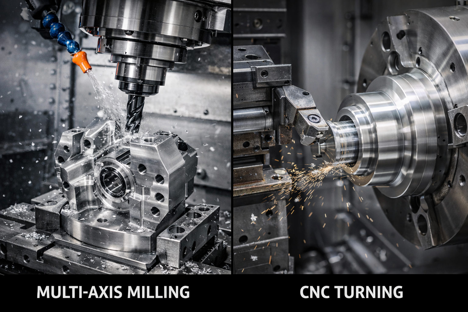
عمليات التفريز وقدرات التعدد المحوري
يستخدم تشغيل التفريز باستخدام الحاسب (CNC) أدوات قطع دوارة لإزالة المادة من قطعة العمل المثبتة على طاولة التشغيل. تخيل ذلك كـ مثقاب عالي السرعة التي يمكنها التحرك في اتجاهات متعددة، لتشكيل الجيوب والشقوق والملامح والأسطح ثلاثية الأبعاد المعقدة. وتحدد عدد المحاور الهندسية الممكنة التي يمكن إنجازها.
الطحن ثلاثي المحاور يُحرّك أداة القطع على طول المحاور X وY وZ — أي من اليسار إلى اليمين، ومن الأمام إلى الخلف، ومن الأعلى إلى الأسفل. ويُنفّذ هذا النوع معظم الأسطح المستوية والجيوب والملامح البسيطة بكفاءة عالية. وهو يُعتبر العمود الفقري للقطع البسيطة، ويوفّر أقل تكلفة ممكنة لوقت التشغيل الآلي.
الطحن رباعي المحاور يُضيف دورانًا حول محور أفقي واحد، ما يسمح لآلة التصنيع باستخدام الحاسوب (CNC) بالوصول إلى الملامح الموجودة على جوانب متعددة من القطعة دون الحاجة إلى إعادة وضعها يدويًّا. وهذا يقلل من وقت الإعداد ويزيد من دقة التصنيع للقطع التي تحتوي ملامح على أكثر من وجه واحد.
خدمات تشغيل CNC ذات المحاور الخمسة تمثل هذه الآلات قمة القدرات في عمليات التفريز. وبفضل حركتها المتزامنة على خمسة محاور، يمكن لهذه الآلات الاقتراب من القطعة المراد تشكيلها من أي زاوية تقريبًا. وبذلك تصبح مكونات الطائرات المعقدة، وشفرات التوربينات، والغرسات الطبية الدقيقة قابلة للتصنيع في إعداد واحد فقط. وعلى الرغم من أن تكلفة وقت التشغيل أعلى، فإن إلغاء الإعدادات المتعددة يجعل التفريز الخماسي المحاور الخيار الاقتصادي الأمثل للأجزاء ذات الأشكال الهندسية المعقدة.
متى يجب تحديد استخدام التفريز متعدد المحاور؟ فكّر في ذلك عند احتواء قطعتك على:
- زوايا مركبة أو أسطح منحوتة
- عناصر موجودة على وجوه متعددة تتطلب علاقات موضعية دقيقة جدًّا
- أجزاء محفورة داخلية (Undercuts) أو تجاويف عميقة مع صعوبة في وصول الأدوات إليها
- جدران رقيقة قد تنحني أو تشوه نتيجة الإعدادات المتكررة
خدمات التشغيل بالدوران للمكونات الأسطوانية
بينما تقوم عملية الطحن بتدوير الأداة، فإن التشغيل الآلي بالحاسوب للدوران (CNC turning) يقوم بتدوير قطعة العمل. وتبقى أداة القطع ثابتة أو تتحرك على طول مسارات مُعرَّفة لتشكيل المادة الدوارة. ويجعل هذا من عملية الدوران مثالية لأي جزء يمتلك تماثلاً دورانياً — مثل المحاور، والبطانات، والتجهيزات، والغلاف الأسطواني.
وتتناول خدمة التشغيل الآلي بالحاسوب للدوران القياسية عمليات مثل التسوية السطحية (facing)، والتنميق الداخلي (boring)، وتصنيع الخيوط (threading)، والتشكيك (grooving)، وقص المخاريط (taper cutting). وغالباً ما تتضمن مراكز الدوران الحديثة أدوات تشغيل نشطة (live tooling)، التي تضيف إمكانات الطحن لإنشاء ملامح مثل الأسطح المسطحة، والثقوب العرضية، والمزالج (keyways)، دون الحاجة إلى نقل القطعة إلى جهاز ثانٍ.
لأجزاء التدوير الصغيرة جدًا أو شديدة التعقيد، توفر عمليات التشغيل بالآلات السويسرية دقة لا مثيل لها. وتستخدم المخارط من النوع السويسري رأس تشغيل قابل للانزلاق وحلقة توجيه تدعم قطعة العمل بالقرب من منطقة القطع مباشرةً. وهذا يقلل من الانحراف إلى أدنى حدٍ ممكن، ويسمح بتحقيق تحملات دقيقة جدًا في المكونات الطويلة والرفيعة. وغالبًا ما تعتمد مكونات الساعات والدبابيس الطبية وموصلات الإلكترونيات على عمليات التشغيل بالآلات السويسرية لتلبية متطلباتها الصارمة.
تُوفِّر خدمات التدوير باستخدام الحاسب الآلي عادةً أوقات دورة أسرع من الطحن للأجزاء الدائرية. فإذا كانت مكوناتك أسطوانية الشكل في جوهرها، فإن عملية التدوير ستكون في الغالب أكثر اقتصاديةً من محاولة طحنها من بلوك مستطيل الشكل.
عمليات متخصصة للهندسات الهندسية المعقدة
تتطلب بعض التحديات التصنيعية عمليات تتجاوز الطحن والتدوير التقليديين. وفيما يلي الحالات التي ينبغي فيها النظر في استخدام التقنيات المتخصصة:
تصنيع الكهرباء المنبعثة (EDM) يستخدم شرارات كهربائية لتآكل المادة، مما يجعله مثاليًا للصلب المقوى والسبائك الغريبة التي قد تُدمِّر أدوات القطع التقليدية. ويتفوق التصنيع بالتفريغ الكهربائي (EDM) في إنشاء زوايا داخلية حادة، وشقوق ضيقة عميقة، وتجاويف قوالب معقدة. أما التصنيع بالتفريغ الكهربائي باستخدام السلك (Wire EDM) فيقوم بقطع الملامح المعقدة بدقة استثنائية، بينما يُنشئ التصنيع بالتفريغ الكهربائي الغاطس (Sinker EDM) أشكال التجاويف المفصَّلة.
الطحن يحقِّق أفضل تشطيبات سطحية وأضيق التحملات المتاحة. وعندما تحتاج إلى خشونة سطحية أقل من Ra 0.4 ميكرومتر أو دقة أبعاد ضمن ±0.0001 بوصة، يصبح الطحن ضروريًّا. ويُطبَّق عادةً بعد المعالجة الحرارية لاستعادة الدقة التي قد تؤثر عليها العمليات الحرارية.
الحفر والتنفيد يُنشئان الثقوب ويُحسِّنانها. فبينما يتم الحفر الأساسي على أي ماكينة طحن، فإن عمليات الحفر المخصصة تُحسِّن السرعة للقطع التي تتطلب عددًا كبيرًا من الثقوب. أما التنفيد فيُحسِّن الثقوب الموجودة ليُحدِّد قطرها وموقعها بدقةٍ عالية، وهو أمرٌ بالغ الأهمية لمواقع تركيب المحامل وميزات المحاذاة.
| نوع العملية | أفضل التطبيقات | الدقة النموذجية | التوافق المادي | التكلفة النسبية |
|---|---|---|---|---|
| الطحن ثلاثي المحاور | الأسطح المستوية، والجيوب، والملامح البسيطة | ±0.005 بوصة (0.127 مم) | جميع المعادن والبلاستيك القابلة للتشغيل الآلي | منخفضة |
| الطحن رباعي المحاور | خصائص متعددة الأوجه، أجزاء مُرقَّمة | ±٠٫٠٠٣ بوصة (٠٫٠٧٦ مم) | جميع المعادن والبلاستيك القابلة للتشغيل الآلي | متوسطة |
| الطحن بخمسة محاور | أسطح ثلاثية الأبعاد معقدة، وأجزاء ذات انحناءات عكسية، وأجزاء طيران فضائية | ±٠٫٠٠٢ بوصة (٠٫٠٥٠ مم) | جميع المعادن والبلاستيك القابلة للتشغيل الآلي | عالية |
| CNC تدوير | أجزاء أسطوانية، ومحاور، ووصلات | ±0.005 بوصة (0.127 مم) | جميع المعادن والبلاستيك القابلة للتشغيل الآلي | منخفض إلى متوسط |
| تشغيل سويسري | أجزاء دقيقة صغيرة، ومكونات طبية | ±٠٫٠٠٠٥ بوصة (٠٫٠١٣ مم) | معظم المعادن وبعض البلاستيكيات | متوسط إلى عالي |
| الـ EDM | المواد المُصلَّبة، والزوايا الحادة، والقوالب | ±٠٫٠٠٠٥ بوصة (٠٫٠١٣ مم) | المواد الموصلة فقط | عالية |
| الطحن | تشطيبات فائقة الدقة، وتسامحات حرجة | ±0.0001 بوصة (0.003 مم) | المعادن المُصلَّبة، والسيراميك | عالية |
يبدأ اختيار العملية المناسبة بفهم هندسة القطعة المطلوبة. هل هي أسطوانية الشكل؟ ابدأ بالتشغيل الدوراني باستخدام التحكم العددي الحاسوبي (CNC). هل تحتوي على ميزات معقدة متعددة الأسطح؟ فكّر في التشغيل بالطحن الخماسي المحاور. هل هي مصنوعة من الفولاذ المُصلَّب وتحتوي على تفاصيل دقيقة جدًّا؟ قد تكون عملية التآكل الكهربائي (EDM) هي الحل الأمثل لك. ويُوصي معظم مقدِّمي خدمات التشغيل الآلي عادةً بالنهج الأمثل أثناء مراجعة التصميم، لكن فهم هذه الفروق يساعدك على التواصل بفعالية وتقييم توصياتهم بدقة.
وبعد توضيح اختيار العملية، تأتي الخطوة الحرجة التالية وهي اختيار المادة المناسبة للتطبيق المطلوب — وهي خطة تؤثر مباشرةً على أداء القطعة وتكلفة تصنيعها.
دليل اختيار المواد للأجزاء المشغولة باستخدام التحكم العددي الحاسوبي (CNC)
لقد حددتَ عملية التشغيل بالآلات المناسبة لهندسة قطعتك. والآن تأتي قرارٌ لا يقل أهميةً عن ذلك: ما هو المادة التي ستُصنع منها هذه القطعة؟ وقد يؤدي الاختيار الخاطئ هنا إلى مكونات تفشل أثناء التشغيل، أو تكلّف أكثر بكثيرٍ مما هو ضروري، أو يثبت أنها غير قابلة للتشغيل بالآلات بكفاءة. أما الاختيار الصحيح فيوازن بين المتطلبات الميكانيكية، والتعرّض البيئي، وقيود الوزن، والميزانية — مع البقاء عمليًّا من حيث التصنيع في الوقت نفسه.
فكّر في اختيار المادة على أنه لغزٌ يتضمّن أجزاء متعددة مترابطة . فمكوّن صمام بحري يحتاج أولاً وأخيراً إلى مقاومة التآكل. أما العارضة المستخدمة في مجال الطيران فهي تتطلّب نسبة عالية من القوة إلى الوزن. وفي المقابل، فإن الترس المستخدم في معالجة الأغذية يتطلّب الامتثال لمتطلبات إدارة الأغذية والأدوية (FDA) ومقاومة التآكل. وكل تطبيقٍ من هذه التطبيقات يشير إلى عائلات مواد محددة، وبداخل كل عائلةٍ توجد درجاتٌ معينةٌ تحسّن الأداء لتلبّي احتياجاتك الدقيقة تماماً.
المعادن وخصائص تشغيلها بالآلات
تظل المعادن حجر الزاوية في التشغيل الدقيق، حيث توفر مزيجًا من القوة والمتانة والأداء الحراري لا يمكن للبلاستيكيات أن تطابقه أبدًا.
سبائك الألومنيوم
عندما يكون الوزن عاملًا مهمًّا ومتطلبات القوة معتدلة، فإن سبائك الألومنيوم تقدِّم قيمة استثنائية. فهي تُشغَّل بسرعة أكبر من الفولاذ، مما يقلل تكاليف الإنتاج، كما تتمتَّع بمقاومة طبيعية للتآكل في العديد من البيئات.
- 6061-T6: المعدن متعدد الاستخدامات العام. يتمتَّع بقوة جيدة وقدرة ممتازة على التشغيل ويمكن لحامه بسهولة. وهو مثالي للمكونات الإنشائية والتجهيزات والغلاف الخارجي.
- 7075-T6: قوة تقارب قوة الفولاذ مع ثلث وزنه فقط. ويُفضَّل استخدامه في تطبيقات الطيران الفضائي والتطبيقات عالية الإجهاد. ويتسم بارتفاع تكلفته وبأن سرعة تشغيله أبطأ قليلًا مقارنةً بالسبيكة 6061.
- 2024:مقاومة استثنائية للتعب الميكانيكي. وتُستخدم عادةً في هياكل الطائرات حيث يشكِّل التحميل الدوري مصدر قلق.
الفولاذ المقاوم للصدأ
عندما تجتمع مقاومة التآكل مع متطلبات القوة، تصبح عمليات تشغيل الفولاذ المقاوم للصدأ ضرورية. وتحتوي هذه السبائك على الكروم الذي يشكّل طبقة أكسيد واقية، لكن هذه الخاصية نفسها تجعل قصّها أكثر صعوبة.
- الفولاذ المقاوم للصدأ 304: الدرجة الأكثر شيوعًا. مقاومة ممتازة للتآكل، وقابِلية جيدة للتشكيل. وتُستخدم في معدات تحضير الأغذية، والأجهزة الطبية، والتطبيقات المعمارية.
- الفولاذ المقاوم للصدأ 316: مقاومة محسَّنة أمام الكلوريدات والبيئات البحرية. وهي أعلى سعرًا قليلًا، لكنها ضرورية في المناطق الساحلية أو عند التعرُّض للمواد الكيميائية.
- 17-4 PH: قابلة للتصليب الحراري لتحقيق قوة عالية. وتجمع بين مقاومة التآكل والخصائص الميكانيكية التي تقترب من خصائص فولاذ الأدوات.
الصلب الكربوني والصلب السبيكي
وبالنسبة لأقصى قوة وصلادة بأقل تكلفة ممكنة للمواد، لا يزال الفولاذ الكربوني لا يُضاهى. ويحتاج هذا النوع إلى طلاء واقٍ أو طلاء كهربائي في البيئات المسببة للتآكل، لكنه يتفوق في الحالات التي يُدار فيها القرار استنادًا إلى نسبة القوة إلى التكلفة.
- فولاذ 1018: منخفض الكربون، وسهل التشغيل واللحام. وهو مثالي لتصنيع المحاور والدبابيس والأجزاء الإنشائية التي ستُغطى بلayers واقية أو تُدهن.
- فولاذ 4140: فولاذ سبائكي قابل للتصنيع الحراري ويتمتّع بمقاومة ممتازة. يُستخدم عادةً في التروس والمحاور والمكونات الميكانيكية الخاضعة لإجهادات عالية.
- فولاذ الأدوات A2/D2: صلادة فائقة ومقاومة استثنائية للتآكل. يُستخدم في القوالب والمخروطات وأدوات القطع نفسها.
البرونز والنحاس الأصفر
توفر هذه السبائك النحاسية خصائص فريدة لا يمكن للفولاذ أو الألومنيوم محاكاتها. وتؤدي عمليات تصنيع أجزاء البرونز باستخدام ماكينات التحكم العددي (CNC) إلى إنتاج أجزاء تتميّز بمقاومة استثنائية للتآكل، واحتكاك منخفض، وخصائص مضادة للميكروبات بشكل طبيعي.
ووفقاً لمتخصصي القطاع، فإن تركيب البرونز — الذي يتكوّن أساساً من النحاس والقصدير — يمنحه مقاومة استثنائية للتآكل وقوة عالية، ما يجعله مثالياً لصناعة التروس والمحامل والمكونات التي تتطلب تماساً ميكانيكياً مستمراً. كما أن تصنيع البرونز يسمح بعمليات قطع ناعمة مع انخفاض خطر التصاق الأسطح (Galling)، مما يؤدي إلى تشطيبات سطحية ممتازة.
- برونز المحامل C932: الخيار الأمثل للبطانات والمحامل. وتتيح خصائصه ذاتية التزييت إطالة عمر المكونات في التطبيقات الدوارة.
- البرونز الألمنيوم: يجمع بين مقاومة التآكل والقوة العالية. ويُفضَّل استخدامه في معدات المارينا والصمامات ومكونات المضخات.
- نحاس 360: أكثر المعادن قابلية للتشغيل بالآلات. وهو ممتاز للأجزاء الزخرفية والمكونات الكهربائية والتجهيزات التي يهم فيها المظهر.
البلاستيكيات الهندسية للأجزاء الدقيقة
ليست كل التطبيقات تتطلب استخدام المعادن. فالبلاستيكيات الهندسية تقدِّم مزايا جذَّابة: خفة الوزن، والتشحيم الطبيعي، والعزل الكهربائي، ومقاومة المواد الكيميائية التي تتفوَّق على العديد من المعادن. وتنتج عمليات تشغيل البلاستيك باستخدام ماكينات التحكم الرقمي الحاسوبي الحديثة مكوناتٍ بدقة تُناصر دقة الأجزاء المعدنية.
الأسيتال (ديلرين)
أصبح بلاستيك ديلرين مترادفًا مع المكونات البلاستيكية الدقيقة. فهذه المادة توفر استقرارًا أبعاديًّا استثنائيًّا، واحتكاكًا منخفضًا، ومقاومة لامتصاص الرطوبة — وهي خصائص تجعلها مثالية لصناعة التروس والمحامل والمكونات المنزلقة.
- قابلية ممتازة للتشغيل بالآلات مع القدرة على تحقيق تحملات ضيقة
- سطح ذاتي التشحيم يقلل من التآكل
- مقاوم للوقود والمذيبات والعديد من المواد الكيميائية
- متوفر بدرجات متوافقة مع إدارة الأغذية والعقاقير (FDA) للاتصال مع المواد الغذائية
النايلون (البولي أميد)
عندما تحتاج إلى قوة ومقاومة للتأثير في مادة بلاستيكية، فإن النايلون القابل للتشكيـل بالآلات يوفّر ذلك. وتتميّز درجات النايلون القابلة للتشكيـل بالآلات بقدرتها على تحمل التطبيقات الميكانيكية الصعبة مع بقائها أخفَّ بكثيرٍ من البدائل المعدنية. ويجب عند تشكيـل النايلون بالآلات الانتباه إلى خاصية امتصاصه للرطوبة، إذ قد تتغيّر أبعاد القطع قليلاً في البيئات الرطبة.
- نايلون ٦/٦: أعلى درجة من القوة والصلابة. وهو الأنسب للتطبيقات الإنشائية.
- نايلون مُصبوب: متوفر على هيئة كتل كبيرة لتصنيع القطع الكبيرة. ويمتاز بسهولة تشكيـله بالآلات أكثر قليلاً مقارنةً بالدرجات المقشّرة.
- نايلون مملوء بالزيت: الزيت المدمج داخل المادة يطيل عمر الخدمة في تطبيقات المحامل.
البوليكربونات
هل تحتاج إلى وضوح بصري مقترنًا بمقاومة التأثير؟ إن تشكيـل البولي كربونات باستخدام ماكينات التحكم العددي الحاسوبي (CNC) يُنتِج مكونات شفافة لا تنكسر تحت الضغط. وتُستخدم هذه المادة عادةً في دروع السلامة، والنوافذ الزجاجية المراقبة، والأغطية الواقية.
- شبه غير قابل للكسر — أقوى بـ٢٥٠ مرة من الزجاج
- يحافظ على الوضوح بعد التشغيل باستخدام التقنيات المناسبة
- نطاق درجة الحرارة من -40°ف إلى 240°ف
- يمكن تلوينه أو طلاؤه لتطبيقات مُعيَّنة
الأكريليك (PMMA)
عندما يكون الوضوح البصري هو العامل الأهم، وتكون مقاومة التصادم عاملًا ثانويًّا، فإن الأكريليك يُشغَّل بسلاسةٍ كبيرة ويُلمَّع ليُعطي نهائيةً بلوريةً صافيةً تمامًا. وغالبًا ما تُحدَّد هذه المادة لصناديق العرض، وأدلة الإضاءة، والمكونات الزخرفية.
البلاستيك عالي الأداء
وفي البيئات القاسية جدًّا، تدفع البلاستيكات المتخصصة الحدود إلى أقصى حدٍّ:
- PEEK: التشغيل المستمر حتى 480°ف، ومقاومة كيميائية ممتازة، وقوة تقترب من قوة بعض المعادن. وهي باهظة الثمن، لكنها لا غنى عنها في التطبيقات الصعبة.
- PTFE (تفلون): أقل معامل احتكاك بين جميع المواد الصلبة. ويعتبر تشغيله تحديًّا، لكنه ضروريٌّ لأغراض الأختام ومعالجة المواد الكيميائية.
- UHMW: مقاومة استثنائية للتآكل والارتداء. ذات تزييت ذاتي ومتوافقة مع متطلبات إدارة الأغذية والعقاقير (FDA) للتعامل مع المواد الغذائية.
مطابقة خصائص المواد لمتطلبات التطبيق
كيف تختار بين هذه الخيارات لمشروعك المحدد؟ ابدأ بتحديد المتطلبات الإلزامية غير القابلة للتفاوض، ثم قم بالتحسين وفق العوامل الثانوية.
متطلبات القوة
إذا كان جزؤك يجب أن يتحمل أحمالًا كبيرة، فإن المعادن تتفوق عمومًا على البلاستيكيات. وفيما يخص المعادن، فإن الترتيب التصاعدي من حيث القوة يكون عادةً كالتالي: الألومنيوم < النحاس الأصفر < الفولاذ الكربوني < الفولاذ المقاوم للصدأ < فولاذ السبائك < التيتانيوم. وعادةً ما يعني ارتفاع القوة ارتفاع تكلفة المادة وبطء عملية التشغيل الآلية، لذا حدد فقط ما تتطلبه تطبيقك فعليًّا.
المقاومة للتآكل
إن التعرُّض للعوامل البيئية يُحدِّد العديد من قرارات اختيار المواد. ففي البيئات الداخلية المعتدلة، يعمل الفولاذ الكربوني مع طلاء مناسب بشكل جيد. أما في حال التعرُّض الخارجي، فيتطلب الأمر استخدام الألومنيوم أو الفولاذ المقاوم للصدأ أو البلاستيكيات. أما في البيئات البحرية والكيميائية، فيتطلَّب الأمر استخدام الفولاذ المقاوم للصدأ من الدرجة 316 أو البرونز الألومنيومي أو بلاستيكيات متخصصة مثل مادة الـPEEK أو الـPTFE.
قيود الوزن
عندما يكون كل غرامٍ مهمًا — كما في مجال الطيران أو المعدات المحمولة أو المكونات المتحركة التي تؤثر في استهلاك الطاقة — تصبح كثافة المادة عاملًا بالغ الأهمية. وتتميَّز البلاستيكيات بأقل كثافة، تليها الألومنيوم، ثم التيتانيوم، ثم الفولاذ. وكثيرًا ما يتفوَّق الألومنيوم عند استخدامه بمقاطع سميكة قليلًا على المواد الأثقل مع الحفاظ على مقاومة مقبولة.
اعتبارات التكلفة
تجمع تكلفة المادة سعر المواد الخام مع وقت التشغيل الآلي. فقد تكون مادة «رخيصة» تُشغَّل آليًّا ببطءٍ أكثر تكلفةً من حيث سعر القطعة المُصنَّعة النهائية مقارنةً بمادة «غالية الثمن» تُقطَع بسرعة. وتتميَّز النحاس الأصفر والألومنيوم بأسرع عمليات التشغيل الآلي بين المعادن. أما الفولاذ المقاوم للصدأ والتيتانيوم فيُشغَّلان آليًّا بأبطأ ما يكون. ومن بين البلاستيكيات، تتميَّز مادتا الأسيتال والنايلون بكفاءة عالية في التشغيل الآلي، بينما تتطلَّب مادة الـPEEK تقنية دقيقة وتنفق وقتًا أطول.
التعرض لدرجة الحرارة
تؤدِّي حدود درجة حرارة التشغيل إلى تضييق الخيارات بسرعة. فتفشل معظم البلاستيكيات عند درجات حرارة تزيد عن ٢٠٠–٢٥٠°فهرنهايت، رغم أن مادة الـPEEK تصل إلى ٤٨٠°فهرنهايت. ويضعف الألومنيوم بشكلٍ كبيرٍ عند درجات حرارة تزيد عن ٣٠٠°فهرنهايت. أما الفولاذ فيحافظ على خصائصه حتى عند درجات حرارة أعلى كثيرًا. فإذا كانت الحرارة جزءًا من بيئتك التشغيلية، فابدأ أولًا باستبعاد المواد التي لن تتحمَّل هذه الظروف.
ما زلت غير متأكد؟ يمتلك معظم مقدِّمي خدمات التشغيل الآلي متخصصين في المواد يمكنهم اقتراح الخيارات المثلى لتطبيقك. ويوفر إعطاؤهم معلوماتٍ كاملةً عن ظروف التشغيل، والأحمال، والتعرض البيئي توصياتٍ أفضل من مجرد طلب «الفولاذ المقاوم للصدأ» أو «الألومنيوم».
وبعد الانتهاء من اختيار المادة، فإن فهم سير عمل التشغيل الآلي من تقديم التصميم إلى الحصول على القطعة النهائية يساعد في وضع توقعات واقعية بشأن الجدول الزمني، ويُحدِّد الفرص المتاحة لتبسيط مشروعك.
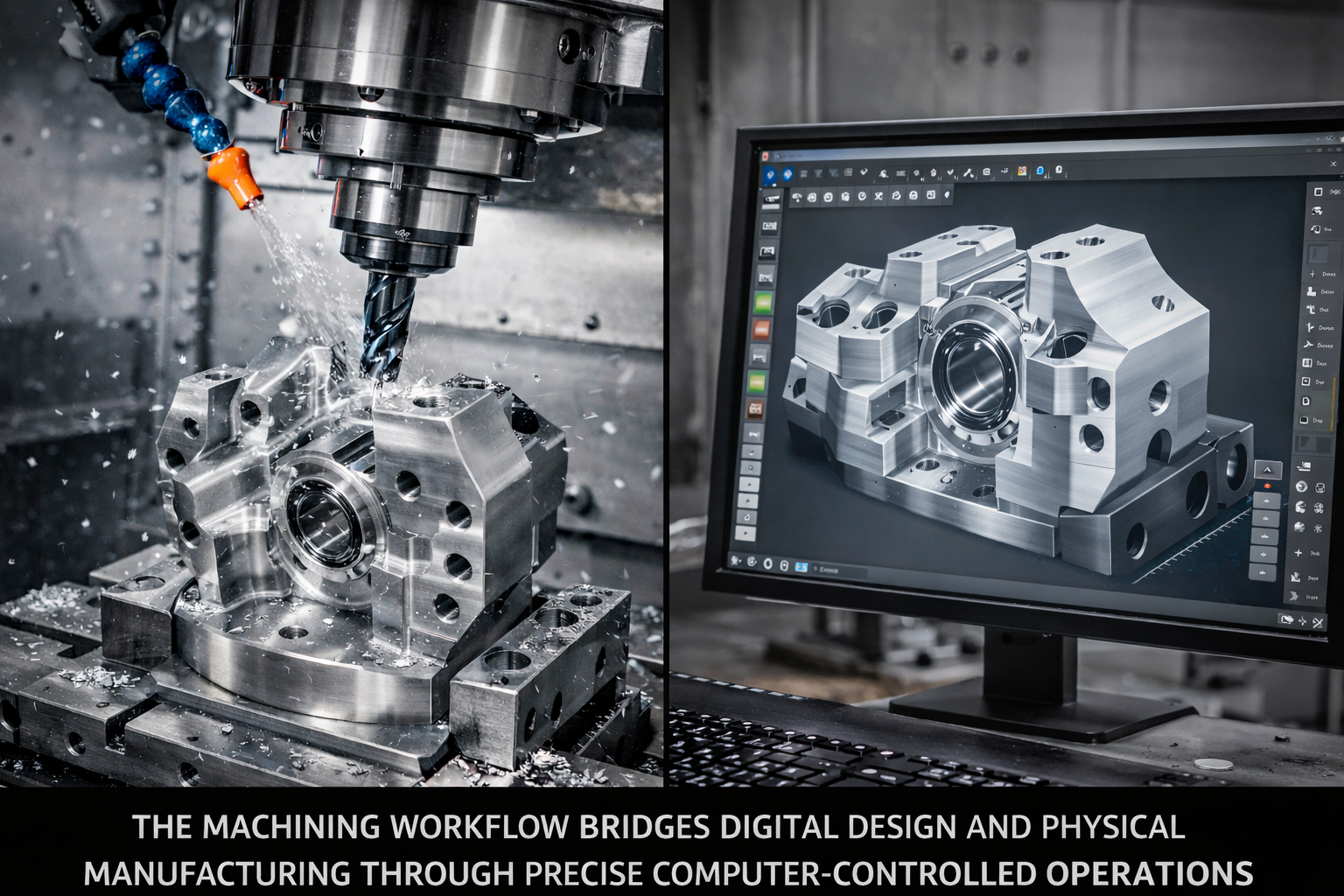
شرح شامل لسير عمل التشغيل الآلي باستخدام الحاسوب (CNC)
لقد اخترتَ العملية والمادة المناسبتين. فما الذي يحدث بالفعل عند تقديم طلبك؟ بالنسبة للكثير من العملاء، يظل سير عمل خدمة التشغيل الآلي غامضًا تمامًا — فتُرسَل التصاميم وتخرج القطع، بينما يبقى كل ما بينهما غامضًا. ويساعد فهم كل مرحلةٍ في وضع توقعات واقعية، وفي تحديد أوجه التأخير المحتملة قبل حدوثها، وفي التواصل مع شريكك التصنيعي بشكل أكثر فعالية.
تتبع الرحلة من ملف الـCAD إلى المكوّن النهائي تسلسلاً منطقياً. فكل مرحلة تُبنى على المرحلة السابقة لها، ومعرفة ما يحدث في كل خطوة تُمكّنك من إعداد الوثائق المطلوبة مسبقاً بشكل أفضل، وطرح الأسئلة المستنيرة طوال عملية الإنتاج.
- إرسال ملف التصميم: توفّر ملفات الـCAD ثلاثية الأبعاد (بصيغة STEP أو IGES أو الصيغ الأصلية) مع الرسومات ثنائية الأبعاد التي تحدّد التسامحات، وأوجه التشطيب السطحي، والأبعاد الحرجة.
- مراجعة التصميم وتغذية راجعة حول إمكانية التصنيع (DFM): يقوم المهندسون بتحليل ملفاتك من حيث قابلية التصنيع، ويُشاركون أية مشكلات محتملة ويقترحون تحسينات.
- شراء المواد: يتم طلب المواد الخام أو سحبها من المخزون وفقاً لمواصفاتك.
- إعداد الآلة وبرمجة التشغيل: يُولّد مبرمجو أنظمة التصنيع بالحاسوب (CAM) مسارات الأدوات وكود الـG، بينما يستعد المشغلون لتشغيل الآلات وتوفير أدوات التشغيل.
- عمليات التجهيز: تنفّذ آلات التحكم العددي الحاسوبي (CNC) التعليمات المبرمَجة لإنشاء أجزائك.
- فحص الجودة: تخضع الأجزاء المُنتَجة للتحقق البُعدي مقابل المواصفات.
- عمليات التشطيب: تطبّق العمليات الثانوية مثل التأكسد الكهربائي (Anodizing)، أو الطلاء (Plating)، أو التلميع (Polishing)، حسب الحاجة.
- التغليف والشحن: يتم حماية الأجزاء وإرسالها إلى منشأتك.
تقديم التصميم ومراجعة الهندسة
تبدأ هذه العملية في اللحظة التي تقوم فيها بتحميل ملفاتك. لكن ما الملفات بالضبط التي يجب أن تتضمنها؟ يؤدي إرفاق الوثائق الكاملة إلى تسريع كل مرحلة لاحقة، بينما تؤدي المعلومات الناقصة إلى تأخيرات وسوء فهم محتمل.
يجب أن يتضمّن طلبك ما يلي:
- نموذج CAD ثلاثي الأبعاد: يوفر تنسيق STEP توافقًا عالميًّا. وينبغي تضمين الملفات الأصلية (Native Files) إذا كانت الميزات المعقدة قد لا تُترجم بدقة تامة.
- رسم ثنائي الأبعاد: حدّد بوضوح التسامحات الحرجة، وتشطيبات السطح، وأي ميزات تتطلب اهتمامًا خاصًّا. ولا تفترض أن النموذج ثلاثي الأبعاد يعبّر عن كل شيء.
- مواصفات المادة: حدد سبيكة الألومنيوم الدقيقة ودرجة تقويتها (مثل: 6061-T6)، بدلًا من الاكتفاء بذكر «ألومنيوم» فقط.
- متطلبات الكمية: تساعد الكميات المطلوبة فورًا والكميات السنوية المتوقعة في تحسين الأسعار واختيار العملية الأنسب.
- سياق الاستخدام: ما الوظيفة التي سيؤديها الجزء؟ توفر هذه المعلومة للمهندسين الأساس اللازم لتقديم توصيات مناسبة حول تصميم القابلية للتصنيع (DFM).
أثناء مراجعة التصميم، يقوم المهندسون بفحص ملفاتك وفقًا لواقع عمليات التصنيع. ووفقًا لوثائق سير العمل في القطاع، فإن عملية تحويل النماذج من برامج التصميم بمساعدة الحاسوب (CAD) إلى برامج التصنيع بمساعدة الحاسوب (CAM) تُحدِّد المشكلات المحتملة قبل أن تتحول إلى مشكلات مكلفة على أرضية المصنع. وتشمل ملاحظات مراجعة قابلية التصنيع (DFM) الشائعة توصياتٍ بتعديل سماكة الجدران، أو تعديل نصف قطر الزوايا الداخلية، أو تخفيف التحملات حيث لا تضيف المواصفات الضيقة قيمة وظيفيةً لكنها ترفع التكلفة.
يتوقع أن تستغرق مراجعة التصميم يومًا إلى ثلاثة أيام عمل للأجزاء القياسية، وقد تمتد المدة لأكثر من ذلك بالنسبة للتجميعات المعقدة أو الأجزاء المصنوعة باستخدام ماكينات التحكم العددي (CNC) ذات التحملات الضيقة والتي تتطلب تحليلًا تفصيليًّا.
من البرمجة إلى القطعة الأولى
وبعد انتهاء مراجعة التصميم وموافقتك على عرض السعر، تبدأ مرحلة التحضير للإنتاج. وتتمثل هذه المرحلة في تحويل تصميمك الرقمي إلى واقع مادي عبر التخطيط الدقيق وإعداد الآلات.
يولّد برمجة نظام التصنيع بالكمبيوتر (CAM) تعليمات رمز G التي تتحكم في حركات الآلة. ويختار المبرمجون أدوات القطع المناسبة، ويحددون معدلات التغذية والسرعة المثلى، ويخططون لمسارات الأداة بكفاءة لتوازن وقت الدورة مع جودة السطح. أما بالنسبة للأجزاء المصنعة حسب الطلب والمعقدة، فقد تتطلب هذه المرحلة البرمجية عدة ساعات من الوقت الهندسي الماهر.
وفي الوقت نفسه، تتم عملية شراء المواد. فعادةً ما تُشحن المواد الشائعة مثل ألومنيوم 6061 أو الفولاذ المقاوم للصدأ 304 من الموردين خلال يومٍ إلى يومين. أما السبائك الخاصة أو الأحجام غير المعتادة فقد تتطلب فترات تسليم أطول — وأحيانًا أسابيعٍ للمواد النادرة.
ويشمل إعداد الآلة ما يلي:
- تركيب أدوات القطع المناسبة في مخزن الأدوات
- تثبيت المادة الخام في التجهيزات أو الماسكات
- إعداد أنظمة الإحداثيات وانحرافات العمل
- تحميل برنامج التحكم العددي المحوسب والتحقق منه
- تشغيل قطع تجريبية للتأكد من أطوال الأدوات ومواقعها
يحظى القطعة الأولى — أي أجزاءك المصنّعة أوليًا — باهتمام إضافي. ويقوم المشغلون بمراقبة ظروف التشغيل بالقطع بدقةٍ شديدة، مع إيقاف العملية مؤقتًا للتحقق من الأبعاد عند النقاط الحرجة. وتُجرى هذه الفحوصات الأولية للقطعة لاكتشاف أي أخطاء في البرمجة أو في إعداد الماكينة قبل أن تنتشر عبر الدفعة بأكملها.
بالنسبة للمكونات البسيطة، يمكن توقع فترة تتراوح بين ثلاثة إلى خمسة أيام من وقت تأكيد الطلب وحتى الانتهاء من القطعة الأولى. أما التصاميم ذات الهندسة المعقدة، أو التحملات الضيقة جدًّا، أو المواد الخاصة، فتؤدي إلى تمديد هذه الفترة وفقًا لذلك. وبالمثل، تستغرق أجزاء الآلات الرقمية (CNC) التي تتطلب عمليات متعددة أو إعدادات متعددة وقتًا أطول من التصاميم التي تُنفَّذ بإعداد واحد فقط.
التحقق من الجودة والتسليم النهائي
وتُكمِل عمليات التشغيل بالقطع العمل التنازلي، لكن أجزاءك ليست جاهزة بعدُ للشحن. ويؤكد التحقق من الجودة أن كل بُعدٍ وتحملٍ ونهاية سطحية يتطابق تمامًا مع مواصفاتك.
وتتفاوت طرق الفحص تبعًا لدرجة تعقيد الجزء والمتطلبات الصناعية:
- القياس اليدوي: تُستخدم الكاليبيرات وأجهزة القياس الميكروميترية وأجهزة قياس الارتفاع للتحقق من الأبعاد الأساسية بسرعة وبتكلفة اقتصادية.
- آلات قياس الإحداثيات (CMM): للمعاملات الضيقة والهندسات المعقدة، يوفّر فحص جهاز القياس ثلاثي الأبعاد (CMM) تحققًا شاملاً للأبعاد مع تقارير موثَّقة.
- اختبار خشونة السطح: تقاس أجهزة البروفيلومتر قيم Ra للتأكد من مواصفات التشطيب.
- الفحص البصري: يقوم مفتشون مدربون بالتحقق من العيوب الجمالية، والحدبات (الزوائد المعدنية)، وجودة التنفيذ.
ويؤدي فشل الفحص إلى اتخاذ إجراء تصحيحي. وقد يمكن معالجة المشكلات الطفيفة عبر عمليات تشغيل إضافية أو تشطيب يدوي. أما الانحرافات الكبيرة فهي تتطلب التخلّص من الأجزاء المتأثرة وإنتاج قطع بديلة — وهذه سببٌ آخر يبرز أهمية مراجعة التصميم بدقة وفحص القطعة الأولى (First Article Inspection).
وتلي عمليات الفحص الناجحة عمليات التشطيب. وتشمل العمليات الثانوية الشائعة ما يلي:
- إزالة الحواف الحادة (الحدبات) وكسر الحواف
- التأكسد أو الطلاء التحويلي الكيميائي للألومنيوم
- الطلاء الكهربائي (بالزنك أو النيكل أو الكروم) للأجزاء الفولاذية
- التشطيب بالطلاء أو التفجير الكروي للحصول على قوام سطحي محدد
- المعالجة الحرارية لتلبية متطلبات الصلادة
تستغرق هذه الخطوات النهائية وقتًا إضافيًّا — عادةً من يومين إلى خمسة أيام إضافية، ويعتمد ذلك على درجة تعقيد العملية وما إذا كانت تُنفَّذ داخليًّا أم تُرسل إلى مورِّدين متخصصين.
وأخيرًا، يضمن التغليف الدقيق حماية استثمارك أثناء النقل. فغالبًا ما تُغلف أجزاء التشغيل الدقيقة بشكل فردي، أو تُحشَّى بالرغوة، أو تُعبَّأ في عبوات مخصصة لمنع التلف. وتتراوح خيارات الشحن بين الشحن البري للجداول الزمنية القياسية، والشحن الجوي العاجل عند الحاجة الماسّة إلى السرعة.
ما المدة الإجمالية من إصدار الطلب حتى التسليم؟ بالنسبة لأجزاء التشغيل الآلي النموذجية المصنوعة من المواد الشائعة وبتسامحات قياسية، تتوقع مدة تتراوح بين أسبوعين وثلاثة أسابيع. ويمكن لخدمات التشغيل العاجل تقليص هذه المدة إلى أقل من أسبوع للأجزاء البسيطة، بينما قد تتطلب التجميعات المعقدة ذات التشطيبات الخاصة أربعة إلى ستة أسابيع أو أكثر.
يُظهر فهم هذه العملية سير العمل أين يمكن تسريع الجداول الزمنية — مثل إكمال الوثائق، وتوافر المواد بسهولة، وتخفيف التحملات حيثما كان ذلك مناسبًا — وكذلك الأماكن التي تنشأ منها التأخيرات عادةً. وبوضع توقعات واقعية مسبقًا، تكون الخطوة التالية هي ضمان أن يكون تصميمك مُحسَّنًا قدر الإمكان لقابلية التصنيع مع تقليل التكاليف غير الضرورية في الوقت نفسه.
إرشادات التصميم التي تقلل التكلفة وفترة التوريد
لقد فهمت عملية سير العمل. وقد اخترت المادة المناسبة. لكن هناك حقيقة يكتشفها العديد من المهندسين في وقتٍ متأخر جدًّا: فالقرارات التصميمية التي تتخذها قبل أن تتواصل حتى مع خدمة التشغيل الآلي قد تُثبِّت ٥٠٪ أو أكثر من التكلفة النهائية لقطعتك. والخبر السار هو أن التعديلات البسيطة على نموذجك في برنامج CAD — والتي تستغرق غالبًا دقائق معدودة فقط — يمكن أن تخفض بشكل كبير كلًّا من السعر ووقت الإنتاج دون المساس بالوظائف المطلوبة.
فكّر في تصميم القابلية للتصنيع (DFM) على أنه التحدث بلغة آلات التحكم العددي بالحاسوب (CNC). فهذه الآلات تتفوق في تصنيع هندسات معينة وتواجه صعوبات في أخرى. وعندما يتوافق تصميمك مع القدرات التصنيعية لهذه الآلات، تسير العمليات بسلاسة تامة. أما عندما يتعارض التصميم مع هذه القدرات، فإن التكاليف ترتفع بشكل كبير وتزداد مدة التسليم بشكل ملحوظ.
الأبعاد الحرجة التي تؤثر في القابلية للتصنيع
إن بعض العلاقات البعدية تحدد مباشرةً مدى كفاءة تنفيذ قطع الآلة باستخدام الحاسب الآلي (CNC). ويساعد فهم هذه العلاقات في تصميم أجزاء يمكن لآلات التصنيع إنتاجها بسرعة وبدقة عالية.
سماكة الجدار
تُشكِّل الجدران الرقيقة واحدةً من أكثر تحديات القابلية للتصنيع شيوعًا. فعندما تصبح الجدران رقيقة جدًّا، فإنها تنحني تحت تأثير قوى القطع، وترتجّ أثناء التشغيل، وقد تنكسر تمامًا. ووفقًا لـ أفضل الممارسات في تصميم القابلية للتصنيع (DFM) من شركة Summit CNC ، يجب أن تبقى سماكة جميع الجدران أكبر من ٠٫٠٢ بوصة — وبشكل عام، كلما زادت السماكة زادت سهولة التشغيل من الناحية التصنيعية.
بالنسبة للمعادن، يُوصى بالسعي إلى أقل سماكة ممكنة للجدران تبلغ ٠٫٠٣٠ بوصة (٠٫٧٦ مم) كلما أمكن ذلك. أما البلاستيك فيتطلب كمية أكبر من المادة على الأقل ٠٫٠٦٠ بوصة (١٫٥ مم)، لأنّه ينحني بسهولة أكبر تحت ضغط الأداة. وغالبًا ما تتطلّب عمليات التشغيل الآلي الصغيرة باستخدام آلات التحكم العددي الحاسوبي (CNC) على الأجزاء ذات الجدران الرقيقة خفض سرعات القطع واستخدام مرورات أخف وزنًا، مما يؤدي مباشرةً إلى زيادة زمن الدورة والتكلفة.
نصف قطر الزوايا الداخلية
إليك حقيقة هندسية تفاجئ العديد من المصممين: لا يمكن لأجزاء التفريز باستخدام آلات التحكم العددي الحاسوبي (CNC) أن تحتوي على زوايا داخلية حادة تمامًا. فالمثاقب الدوارة تترك نصف قطرًا يساوي قطرها. ولذلك فإن طلب زوايا أشد حدةً مما تسمح به أدوات التصنيع القياسية يفرض استخدام أدوات أصغر حجمًا ومثاقب ذات مدى أطول، ما يؤدي إلى زيادة كبيرة في زمن التشغيل.
التوصية؟ صمّم نصف قطر الزوايا الداخلية بحد أدنى قدره ٠٫٠٦٢٥ بوصة (١٫٦ مم)، أو بشكل أفضل، ٠٫١٢٥ بوصة (٣٫٢ مم) عندما يسمح التصميم بذلك. وهذا يسمح باستخدام أدوات قياسية تعمل عند السرعات المثلى. وعندما تتطلب الوظيفة وجود زوايا داخلية حادة، فكّر في استخدام تقنية التآكل الكهربائي (EDM) كعملية بديلة، لكن توقّع ارتفاع التكاليف بشكل كبير.
أعماق الجيوب والتجاويف
تؤدي الجيوب العميقة إلى مشاكل في وصول الأدوات. وكلما زاد عمق التجويف بالنسبة إلى قطر الأداة المطلوبة، زاد احتمال حاجتك إلى أدوات متخصصة طويلة المدى، والتي تكون أكثر تكلفة وأبطأ في التشغيل. وتوصي الإرشادات الصناعية بالحد من عمق الجيوب بحيث لا يتجاوز ستة أضعاف أصغر نصف قطر زاوية موجود في ذلك الجيب.
فعلى سبيل المثال، إذا كانت نصف قطر زوايا جيبك تساوي ٠٫١٢٥ بوصة، فاحرص على أن يظل العمق أقل من ٠٫٧٥ بوصة. ولا يعني تجاوز هذه النسبة أن التشغيل الآلي يصبح مستحيلاً، بل يعني فقط أنه سيصبح أكثر تكلفة وأطول زمنياً، حيث يضطر المشغلون إلى الانتقال إلى قواطع متخصصة تكون عرضة للاهتزاز والانكسار.
نسبة عمق الثقب إلى قطره
تعمل المثاقب القياسية ذات التواء الدوران بكفاءة تصل إلى نسب عمق-إلى-قطر تبلغ حوالي ٤:١. ويمكن حفر ثقب قطره ٠٫٢٥٠ بوصة حتى عمق ١ بوصة دون الحاجة إلى اعتبارات خاصة. وعندما تتجاوز هذه النسبة، يصبح من الضروري استخدام مثاقب متخصصة، ودورات الحفر المتقطعة (Peck-drilling)، وزيادة درجة الحيطة والحذر.
للحفر العميق (بنسبة ١٠:١ أو أكبر)، قد يتطلب الأمر استخدام طريقة الحفر بالبندقية (Gun Drilling) أو التفريغ الكهربائي (EDM)، وهما عمليتان تُضافان تكلفةً كبيرةً. وعند الإمكان، صمِّم الثقوب بحيث لا تكون أعمق مما هو ضروري، وفكِّر في استخدام الثقوب المُخترِقة بدلًا من الثقوب العمياء، لأنها أسرع في التصنيع وأسهل في الفحص.
| ميزة التصميم | التحديد الموصى به | لماذا يهم ذلك؟ | الأثر على التكلفة |
|---|---|---|---|
| السمك الأدنى للجدار | المعادن: ≥٠٫٠٣٠ بوصة (٠٫٧٦ مم) البلاستيك: ≥٠٫٠٦٠ بوصة (١٫٥ مم) |
يمنع الانحناء والاهتزاز والانكسار أثناء عمليات القطع باستخدام ماكينات التحكم العددي (CNC) | تؤدي الجدران الرقيقة إلى زيادة زمن التشغيل بنسبة ٢٠–٤٠٪ |
| نصف قطر الزوايا الداخلية | ≥٠٫٠٦٢٥ بوصة (١٫٦ مم)، ويُفضَّل أن تكون ≥٠٫١٢٥ بوصة | تناسب أدوات التجهيز القياسية؛ وتتجنب استخدام القواطع طويلة المدى | قد تضاعف الزوايا الحادة زمن التشغيل |
| عمق الجيب | ≤ ٦ أضعاف نصف قطر أصغر زاوية | يسمح باستخدام الأدوات القياسية؛ ويقلل من الاهتزاز وانكسار الأدوات | تزيد الجيوب العميقة من زمن الدورة بنسبة 30–50% |
| نسبة عمق الثقب إلى قطره | ≤٤:١ للحفر القياسي | تعمل المثاقب القياسية بكفاءة عالية؛ ولا تتطلب دورات حفر متقطعة (Peck Cycles) | قد تتطلب الثقوب العميقة وقت حفر يعادل ضعفي أو ثلاثة أضعاف الوقت القياسي |
| عمق الخيط | ≤٣ أضعاف القطر الاسمي | تتمكن البراغي القياسية من الوصول بسهولة؛ وتُحقِّق تداخلًا تامًّا للخيوط | يؤدي العمق الزائد إلى زيادة وقت الإعداد والمخاطر المرتبطة به |
| الحصون | يجب تجنُّبه عند الإمكان؛ واستخدام أبعاد الشقوق القياسية على شكل حرف T | يتطلب أدوات خاصة وعمليات إضافية | يُضيف كل انخفاض في التصميم (Undercut) ما يتراوح بين ٢٥ و١٠٠ دولار أمريكي أو أكثر لكل قطعة |
تجنب الأخطاء الشائعة في التصميم
قد تبدو بعض القرارات التصميمية منطقية على الشاشة، لكنها تُسبِّب مشكلات في ورشة الإنتاج. ويؤدي التعرُّف على هذه الأنماط مُسبقًا—قبل إرسال ملفاتك—إلى تجنب دورات المراجعة المتكررة ومنع المفاجآت غير المتوقعة في الميزانية.
تحديد تسامحات مفرطة
قد تكون هذه أخطر غلطة من حيث التكلفة في مرحلة اختيار المواد وتصميم الأجزاء لتصنيعها باستخدام ماكينات التحكم العددي (CNC). ووفقًا لتحليل تكاليف التسامح المقدَّم من خبراء القطاع، فإن تشديد التسامح يؤدي إلى ارتفاع التكاليف بشكل أسّي: فالتقنية الدقيقة ±٠٫٠٠٥ بوصة تكلِّف تقريبًا ضعف التكلفة القياسية، بينما تكلِّف التقنية الدقيقة ±٠٫٠٠١ بوصة أربعة أضعاف التكلفة القياسية. أما التسامح الفائق الضيق ±٠٫٠٠٠١ بوصة فقد يرفع التكلفة بنسبة تتراوح بين ١٠ و٢٤ ضعفًا.
السؤال الحقيقي الذي ينبغي طرحه هو: ماذا يحدث إذا اختلف هذا البُعد بمقدار ±٠٫٠٥ مم؟ وإذا كانت الإجابة «لا يحدث شيء حرج»، فإن التسامح القياسي سيكون الخيار الأمثل لك. واستخدم التسامح المشدَّد فقط في الحالات التالية:
- الأسطح المتداخلة التي يهم فيها دقة التركيب
- مقاعد المحامل وواجهات العمود
- الأسطح المانعة للتسرب الخاصة بالحلقات التوصيلية (O-rings) أو الحشوات (gaskets)
- السمات التي تؤثر في الوظيفة الحرجة أو السلامة
لكل شيء آخر — الأسطح الخارجية، والخصائص غير الوظيفية، ومناطق التجميل — فإن التسامحات القياسية البالغة ±٠٫٠٠٥ بوصة (±٠٫١٢٧ مم) تؤدي المهمة بشكل ممتاز وبتكلفة أقل بكثير.
تصميم الخصائص التي تُعيق وصول الأدوات
تتطلب عمليات تصنيع البلاستيك باستخدام آلات التحكم العددي بالحاسوب (CNC) وكذلك تصنيع المعادن بنفس الطريقة وصولاً فيزيائيًا للأداة إلى كل خاصية. ويبدو هذا واضحًا، لكن التصاميم تصلنا غالبًا وتحتوي خصائص لا يمكن للأدوات الوصول إليها إطلاقًا — أو لا يمكنها الوصول إليها سوى عبر إعدادات متخصصة باهظة الثمن.
تشمل مشاكل الوصول الشائعة ما يلي:
- شقوق ضيقة عميقة يتجاوز فيها قطر الأداة عرض الشق
- خصائص مخفية خلف الجدران أو التراكيب البارزة
- تجويفات داخلية لا توجد لها مسار دخول للأداة
- نصوص أو نقوش في المناطق المنخفضة (المُحفورة)
قبل الانتهاء من تصميمك، قم بتتبع مسار أداة القطع ذهنيًّا نحو كل خاصية. فإذا عجزت عن تصور وصول الأداة إلى الخاصية، فسيكون التصنيع صعبًا أو مستحيلاً دون استخدام تجهيزات إضافية مبتكرة ترفع التكلفة.
تحديد الزوايا المُدوَّرة (Fillet) بدلًا من الزوايا المائلة (Chamfer)
غالبًا ما تحتاج الحواف الخارجية إلى نوعٍ من التقطيع — إما تقويس (مستدير) أو تقليص زوايا (مائل). ومن منظور التشغيل الآلي، يتفوق تقليص الزوايا من حيث التكلفة والسرعة. وكما تشير إرشادات تصميم القابلية للتصنيع (DFM)، فإن تشغيل التقويس يتطلب مسارات أدوات ثلاثية الأبعاد معقدة أو أدوات متخصصة لتقريب الزوايا، بينما يمكن إنجاز تقليص الزوايا بسهولة باستخدام مثاقب تقليص الزوايا القياسية.
ما لم تتطلّب تطبيقك تحديدًا حوافًا مستديرة — لأسباب تتعلق بالراحة البشرية أو الديناميكا الهوائية أو الحد من تركيز الإجهادات — فحدّد تقليص الزوايا لتقليل وقت التشغيل الآلي.
إضافة التعقيد لأغراض الجمالية
بدت تلك النمط الزخرفي رائعة في برنامج التصميم بمساعدة الحاسوب (CAD). لكن كل عنصر إضافي يتطلب وقت تشغيل آلي إضافي. فالعناصر الجمالية المعقدة — مثل الملمس المتشعب، والمنحنيات غير الوظيفية، والنقش التفصيلي — تزيد التكلفة دون تحسين الأداء الوظيفي.
عند تحسين التصميم للإنتاج، ابدأ دائمًا بالتصميم الذي يركّز على الوظيفة. وفكّر فيما إذا كانت الهندسات المعقدة ضرورية حقًّا للتطبيق النهائي لقطعتك، أم أن البدائل الأبسط تحقّق الغرض نفسه.
تحسين التصميم الخاص بك لمرحلة الإنتاج
وبالإضافة إلى تجنُّب الأخطاء، فإن اتخاذ قرارات تصميمية استباقية يُسرِّع عملية الإنتاج ويقلل التكاليف. وتتطلب هذه التحسينات جهدًا تصميميًّا ضئيلًا، لكنها تحقِّق فوائد تصنيعية كبيرة.
تقليل التجهيزات
ففي كل مرة يتعيَّن فيها إعادة وضع القطعة داخل الماكينة — سواء عبر قلبها أو تدويرها أو إعادة تثبيتها — يزداد وقت الإعداد ويظهر احتمال وقوع أخطاء موضعية بين السمات المختلفة. أما التصاميم التي يمكن إنجازها في إعداد واحد فقط فهي أقل تكلفة وأكثر دقةً من التصاميم التي تتطلَّب أكثر من اتجاهٍ واحدٍ أثناء التشغيل.
راجع تصميمك مع التركيز على خفض عدد عمليات الإعداد:
- هل يمكن الوصول إلى السمات الموجودة على الوجوه المقابلة من جانب واحد باستخدام ثقوب عابرة؟
- هل السمات المتعددة الوجوه ضرورية حقًّا، أم يمكن دمجها في سمة واحدة؟
- هل قد يؤدي تغيير بسيط في الشكل الهندسي إلى إلغاء عملية القلب تمامًا؟
استخدم أحجام الأدوات القياسية
هل الأبعاد القطرية للثقوب هي ٠٫٢٥٠ بوصة أو ٠٫٣٧٥ بوصة أو ٠٫٥٠٠ بوصة؟ إن الثاقبات القياسية رخيصة الثمن ومتوفرة فورًا. أما إذا كانت الأبعاد القطرية للثقوب ٠٫٢٣٧ بوصة أو ٠٫٤٨٩ بوصة، فستتطلَّب عمليات توسعة مخصصة أو تشغيل بالتنظيف الداخلي (Boring)، ما يزيد الوقت والتكلفة.
وبالمثل، يسمح تحديد أحجام الخيوط القياسية (10-32، 1/4-20، M6x1.0) باستخدام القواطع والغرسات المتوفرة تجاريًّا بسهولة. أما الخيوط غير القياسية فهي تتطلب أدوات خاصة قد تحتاج إلى طلبها.
حدد شكل المادة الاستراتيجي
يؤثر شكل المادة الخام على كمية التشغيل الآلي المطلوبة. فالقطعة المصممة لتتناسب بكفاءة داخل أبعاد السبائك أو الصفائح أو القضبان القياسية تُهدر كمية أقل من المادة وتُشغَّل آليًّا بشكل أسرع مقارنةً بتلك التي تتطلب كتلًا أكبر من اللازم مع عمليات قص خشن واسعة النطاق.
تواصل مع خدمة التشغيل الآلي الخاصة بك بشأن أحجام المخزون المتاحة قبل إقرار الأبعاد الخارجية النهائية. ففي بعض الأحيان، يؤدي إضافة 0.050 بوصة إلى أحد الأبعاد إلى إمكانية استخدام المخزون ذي الحجم الأصغر التالي، مما يقلل من تكلفة المادة ووقت التشغيل الخشن.
خذ في الاعتبار التحملات المخصصة للنماذج الأولية مقابل التحملات المخصصة للإنتاج
أثناء مرحلة إنشاء النموذج الأولي، فإنك تُجري عملية التحقق من مفاهيم التصميم — وليس إنتاج المنتجات النهائية. ويؤدي البدء بتسامحات أقل صرامة إلى خفض تكلفة النموذج الأولي بنسبة ٤٠–٦٠٪ وفقًا لتحليلات القطاع الصناعي. ويمكنك دائمًا تشديد التسامحات الخاصة بأبعاد معينة لاحقًا إذا أثبت الاختبار ضرورة ذلك.
ويؤدي هذا النهج التكراري — أي إنشاء نموذج أولي باستخدام تسамحات قياسية، ثم إجراء الاختبارات، ثم تشديد التسامحات فقط في الأجزاء التي يكشف عنها الاختبار كونها بالغة الأهمية — إلى تحقيق نتائج أفضل وبتكلفة إجمالية أقل مقارنةً بتحديد متطلبات دقيقة جدًّا منذ البداية.
لا يعني تحسين التصميم التنازل عن وظائف جزئك. بل يعني أن تُعبِّر عن متطلباتك بطريقة تتماشى مع القدرات التصنيعية. وعندما تتطابق التسامحات والخصائص والهندسات مع ما تؤديه آلات التحكم العددي بالحاسوب (CNC) بكفاءة عالية، فإن الجميع ينتفع: فتحصل أنت على أجزاء أفضل وبسرعة أكبر وبتكلفة أقل.
وبمجرد أن يصبح تصميمك مُحسَّنًا من حيث إمكانية التصنيع، فإن الفهم الدقيق للتسامحات والتشطيبات السطحية القابلة للتحقيق فعليًّا — ولتكاليفها — يصبح المعلومة الحرجة التالية التي يجب سدها.
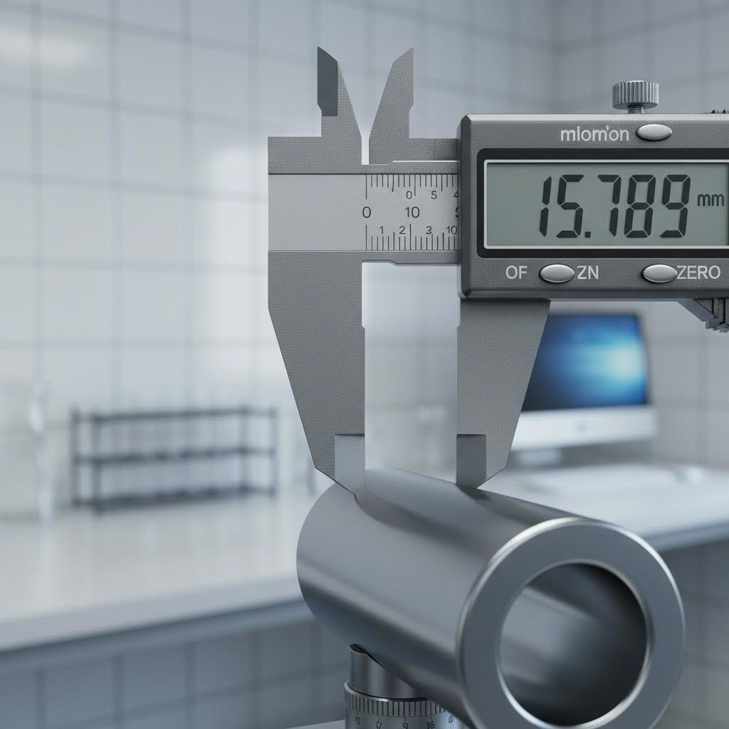
التسامحات وأعمال التشطيب السطحي مُبَسَّطة
لقد صمَّمت جزءك مع مراعاة قابليته للتصنيع. لكن ما مدى الدقة التي يمكن أن يحققها خدمة التصنيع الآلي فعليًّا؟ وما نوعية التشطيب السطحي التي ينبغي أن تتوقعها؟ هذه الأسئلة بالغة الأهمية: فالتحديد المُفرط في التساهل يؤدي إلى عدم أداء الأجزاء لوظائفها بشكل صحيح؛ أما التحديد المُفرط في الضيق فيؤدي إلى ارتفاع التكاليف بشكل كبير دون إضافة قيمة فعلية.
إن فهم التسامحات وأعمال التشطيب السطحي يحوِّلك من شخصٍ يكتفي بقبول العروض السعرية كما هي، إلى شخصٍ يتخذ قراراتٍ مستنيرةٍ بشأن متطلبات الدقة. فلنفكّ رموز هذه المواصفات حتى تتمكن من التواصل بدقةٍ حول ما يتطلبه تطبيقك — لا أكثر، ولا أقل.
التسامحات القياسية مقابل متطلبات التسامح الضيق
كل بُعدٍ في الجزء المصنّع آليًّا يسمح بمدى معيّن من التباين. وهذا المدى هو التسامح — أي الفرق بين أكبر وأصغر قياسٍ مقبولٍ. ولا تُنتج أي عملية تصنيع أجزاءً مثاليةً تمامًا، لكن التصنيع باستخدام الحاسب الآلي (CNC) يقترب من ذلك إلى حدٍّ مذهل.
التسامحات القياسية تمثل ما تحققه الآلات في ظل الظروف التشغيلية العادية دون اتخاذ إجراءات خاصة. ولتُجسِّد ذلك بالنسبة لمعظم شركات التصنيع الدقيق، فإنها تعني:
- الأبعاد الخطية: ±0.005" (±0.127مم)
- أقطار الثقوب: ±0.005" (±0.127مم)
- الميزات الزاوية: ±0.5°
وفقًا للمواصفات الصناعية الصادرة عن شركة فاكتورم (Factorem)، فإن هذه التحملات القياسية تراعي التغيرات الطبيعية التي تطرأ على خصائص المواد، واهتراء الأدوات، والتمدد الحراري، وموضع الآلة، دون الحاجة إلى تقنيات خاصة أو أوقات دورة ممتدة.
التسامح الضيق تتطلب عنايةً إضافيةً — مثل تقليل سرعات القطع، وزيادة تكرار أخذ القياسات، وتوفير بيئات خاضعة للتحكم في درجة الحرارة، واستخدام معدات متخصصة. وعادةً ما تُحدَّد الأجزاء المصنَّعة بدقة عالية والتي تتطلب تحملات ضيقة بالآتي:
- درجة الدقة: ±0.001 بوصة إلى ±0.002 بوصة (±0.025 مم إلى ±0.050 مم)
- دقة عالية: ±0.0005 بوصة (±0.013 مم)
- الدقة الفائقة: ±0.0001 بوصة (±0.003 مم) — وتتطلب عمليات طحن أو معدات متخصصة
متى تحتاج فعليًّا إلى تحملات ضيقة؟ ركِّز على المتطلبات الوظيفية:
- التجميعات ذات التثبيت بالضغط حيث يجب التحكم بدقة في التداخل
- مقاعد المحامل التي تتطلب مسافات تطابق أو تداخل محددة
- أسطح الختم حيث تؤدي الفجوات إلى التسرب
- المكونات المُتَطابِقة التي يجب أن تتماشى تمامًا
بالنسبة لأجزاء التشغيل على آلات التحكم العددي (CNC) الدوارة مثل المحاور والبطانات، فإن مقاسات المحامل تتطلب عادةً تحملات ضيقة جدًّا على القطر والتناسق المحوري. وبالمثل، فإن تشغيل الفولاذ المقاوم للصدأ لمكونات الصمامات يتطلب غالبًا دقة عالية على أسطح الإغلاق مع السماح باستخدام تحملات قياسية في الأجزاء الأخرى.
| درجة التسامح | النطاق النموذجي | التطبيقات الشائعة | عامل تكلفة إضافية |
|---|---|---|---|
| القياسي | ±0.005" (±0.127مم) | الأبعاد غير الحرجة، والغلاف الخارجي، والدعامات، والأغطية | 1.0x (الأساس) |
| الدقة | ±0.002 بوصة (±0.050 مم) | أجزاء التشغيل بالتحكم العددي (CNC) المُمَشَّطة ذات الميزات المتداخلة، وحوامل المحامل | 1.5–2.0 ضعف |
| دقة عالية | ±0.0005 بوصة (±0.013 مم) | أجزاء مُصنَّعة باستخدام آلات التحكم العددي الحاسوبي (CNC) للصناعات الجوية والفضائية، والغرسات الطبية، وحوامل المرايا البصرية | ٣٫٠–٤٫٠× |
| الدقة الفائقة | ±٠٫٠٠٠١ بوصة (±٠٫٠٠٣ مم) | كتل القياس، وثوابت الفحص الحرجة، وأشباه الموصلات | ٨٫٠–٢٤٫٠× |
خيارات تشطيب السطح والتطبيقات
وبينما تُنظِّم التسامحات الأبعاد، فإن حالة السطح تصف قوام السطح — أي القمم والقيعان المجهرية التي تتركها أدوات القطع. وفقًا لـ معايير ASME الواردة في دليل أساسيات الهندسة الهندسية والتفاوتات (GD&T Basics) فإن حالة السطح تتكون من ثلاثة عناصر: الخشونة (الانحرافات الدقيقة)، والموجية (التغيرات الأوسع في المسافات)، واتجاه النسيج (النمط الاتجاهي الناتج عن عمليات التشغيل الآلي).
المعلَّمة الأكثر تحديدًا شيوعًا هي Ra (متوسط الخشونة) - متوسط الحسابي لانحرافات ارتفاع السطح عن الخط المتوسط، ويُقاس بوحدة الميكرو إنش (μin) أو الميكرومتر (μm). وكلما انخفضت القيم المُشار إليها بـ Ra، كان السطح أكثر نعومة.
القيم النموذجية لـ Ra التي يمكن تحقيقها حسب العملية:
- الطحن القياسي: 63–125 ميكرو إنش (1.6–3.2 ميكرومتر)
- الطحن الدقيق: 32–63 ميكرو إنش (0.8–1.6 ميكرومتر)
- التشكيـل بالدوران القياسي: 63–125 ميكرو إنش (1.6–3.2 ميكرومتر)
- التشكيـل بالدوران الدقيق: 16–32 ميكرو إنش (0.4–0.8 ميكرومتر)
- الطحن: 8–32 ميكرو إنش (0.2–0.8 ميكرومتر)
- التلميع: ٢–٨ ميكرو إنش (٠٫٠٥–٠٫٢ ميكرومتر)
ما نوع التشطيب الذي تتطلبه تطبيقك فعليًّا؟ خذ هذه الإرشادات في الاعتبار:
- الأسطح التجميلية / غير الملامسة: ١٢٥ ميكرو إنش (٣٫٢ ميكرومتر) — تشطيب قياسي بعد التشغيل الآلي، وهو مقبول تمامًا
- التلامس الميكانيكي العام: ٦٣ ميكرو إنش (١٫٦ ميكرومتر) — كافٍ لمعظم حالات التلامس المنزلق أو الدوراني
- أسطح الإحكام: ٣٢ ميكرو إنش (٠٫٨ ميكرومتر) — مطلوب لأخدود حلقات الأختام (O-rings) وأسطح الحشوات (gaskets)
- الأسطح الدوارة: ١٦–٣٢ ميكرو إنش (٠٫٤–٠٫٨ ميكرومتر) — حرجٌ لضمان التشحيم السليم وطول عمر التآكل
- التطبيقات البصرية أو التزيينية: ٨ ميكرو إنش (٠٫٢ ميكرومتر) أو أفضل من ذلك — يتطلب عمليات تلميع ثانوية
غالبًا ما تستخدم المواصفات الدولية Rz (عمق الخشونة المتوسط) بدلًا من Ra. وباعتبار تقريبي، تكون قيم Rz عادةً أعلى بـ ٤–٧ مرات من قيم Ra للسطح نفسه، رغم أن هذه العلاقة تتفاوت حسب درجة انتظام السطح.
موازنة الدقة مع الجدوى الاقتصادية للإنتاج
هذه هي الحقيقة المُزعجة: إن تشديد التحملات يعني دائمًا ارتفاع التكاليف. وكما يشير خبراء التحملات، فإن هذه العلاقة ناتجة عن عدة عوامل:
- انخفاض سرعات التشغيل الآلي للحد من انحراف الأداة والتأثيرات الحرارية
- زيادة تكرار الفحص أثناء الإنتاج وبعده
- ارتفاع معدلات الهدر مع ضيق نطاقات القبول
- المعدات المتخصصة لمتطلبات الدقة الفائقة
- بيئات خاضعة للتحكم المناخي للقياسات الحرجة
ما أفضَل نهجٍ من حيث التكلفة؟ تطبيق التسامحات الضيقة بشكل انتقائي. راجع تصميمك واسأل نفسك: ما العنصر الذي يفشل فعليًّا إذا اختلف هذا البُعد عن التسامح القياسي؟ بالنسبة لأجزاء التشغيل الدقيقة التي تتطلب الوظيفة فيها فعلاً الدقة، فحدد هذه التسامحات دون تردد. أما بالنسبة لجميع الأجزاء الأخرى، فإن التسامحات القياسية تحقق أداءً مكافئًا بتكلفة أقل بكثير.
طرق التحقق مهمة أيضًا
كيف تؤكد خدمات التشغيل أن التسامحات المحددة قد تم الوفاء بها؟ يعتمد الجواب على ما حددته أنت:
- التسامحات القياسية: توفر الكاليبيرات وأجهزة القياس الميكروميترية والمقاييس التصريحية/الرفضية (Go/No-Go) تحققًا سريعًا واقتصاديًا
- التحملات الدقيقة: تولِّد آلات قياس الإحداثيات (CMMs) تقارير أبعادية شاملة مع إمكانية تتبع موثَّقة
- نهاية السطح: تقاس قيم Ra مباشرةً باستخدام أجهزة قياس الخشونة (Profilometers)، مما يوفِّر تحققًا موضوعيًّا
- محددات GD&T: تتحقق التجهيزات المتخصصة وبرمجة آلات قياس الإحداثيات (CMM) من العلاقات الهندسية المعقدة
للاستخدامات الحرجة، اطلب وثائق الفحص مع قطع الغيار الخاصة بك. وتقدِّم معظم شركات التشغيل الدقيق تقارير أبعاد تُظهر القيم المقاسة فعليًّا مقارنةً بالمواصفات المطلوبة — وهي وثائق تصبح ضرورية لتتبع الجودة في الصناعات الخاضعة للتنظيم.
إن فهم ما يمكن تحقيقه — وما تكلفة تحقيقه — يمنحك السيطرة على المفاضلة بين الدقة والجوانب الاقتصادية. وبمجرد تحديد التحملات والتشطيبات بشكل مناسب، يصبح السؤال التالي: هل يُعَدُّ التشغيل باستخدام آلات التحكم العددي (CNC) العملية المناسبة لتطبيقك حقًّا، أم أن طرق التصنيع البديلة ستخدم احتياجاتك بشكل أفضل؟
التشغيل باستخدام آلات التحكم العددي (CNC) مقابل طرق التصنيع البديلة
لقد أتقنتَ التحملات، وحسّنت تصميمك، واخترت المادة المثلى. لكن إليك سؤالاً جديرًا بالطرح قبل الالتزام بأي خدمة تشغيل آلي: هل تشكيل المعادن باستخدام الحاسب الآلي (CNC) هو بالفعل الطريقة التصنيعية المناسبة لمشروعك؟ في بعض الأحيان يكون الجواب نعمٌ قاطع. وفي أوقات أخرى، تُحقِّق العمليات البديلة نتائج أفضل وبتكلفة أقل.
هذا لا يتعلّق بإعلان تفوّق طريقة واحدة على غيرها. فكل منهجية تصنيع لها نطاقها الأمثل — أي مزيجٌ محدَّد من الكمية والتعقيد والدقة والميزانية، حيث تتفوّق فيه على جميع الطرق البديلة. وفهم هذه النطاقات المثلى يساعدك على اتخاذ قرارات أكثر ذكاءً، ويجنّبك التناقضات المكلفة بين العملية المختارة ومتطلبات المشروع.
متى يكون التصنيع الإضافي خيارًا أكثر منطقية
تطوّرت الطباعة ثلاثية الأبعاد من كونها وسيلة تجريبية سريعة إلى خيار تصنيعي مشروعٍ لتطبيقات محددة. لكن متى ينبغي أن تختار التصنيع الإضافي بدلًا من التصنيع الطردي؟
وفقًا لـ تحليل مقارن من شركة Ultimaker تتفوق طباعة ثلاثية الأبعاد في إنتاج الأشكال الهندسية المعقدة والهياكل الداخلية التي يصعب أو يستحيل تحقيقها باستخدام طرق التصنيع التقليدية. فكِّر مثلاً في الهياكل الشبكية لتقليل الوزن، أو القنوات الداخلية للتبريد، أو الأشكال العضوية التي تتبع مسارات الإجهادات بدلًا من قيود التشغيل الآلي.
اختر الطباعة ثلاثية الأبعاد عندما:
- الكمية منخفضة جدًّا (١–١٠ أجزاء) - لا توجد تكاليف إعداد مما يجعل إنتاج الدفعات الصغيرة اقتصاديًّا
- الهندسة معقدة للغاية - يمكن طباعة الميزات الداخلية، والانحناءات السفلية (Undercuts)، والأشكال العضوية بسهولة
- السرعة هي العامل الأهم - بدائل النماذج الأولية السريعة باستخدام التشغيل الآلي بالحاسوب (CNC) يمكن أن تُسلَّم خلال ليلة واحدة
- خصائص المادة ثانوية - عندما لا تكون المتانة والدقة عوامل حاسمة
اختر التشغيل الآلي بالحاسوب (CNC) بدلًا من ذلك عندما:
- خصائص المادة لها أهمية كبيرة - تظل الأجزاء المصنوعة آليًّا تحتفظ بكامل مقاومة المادة دون وجود خطوط طبقية
- الدقة أمرٌ بالغ الأهمية - تحقِّق عمليات التصنيع باستخدام الحاسب الآلي (CNC) تحملات بقيمة ±0.025 مم، مقارنةً بتحمُّلات تتراوح بين ±0.1 مم و±0.5 مم في معظم عمليات الطباعة ثلاثية الأبعاد
- نوعية السطح لها وزنٌ كبير - تصل خشونة أسطح الأجزاء المصنوعة آليًّا إلى 0.8 ميكرومتر (Ra)، مقارنةً بـ 15 ميكرومتر للأجزاء المطبوعة
- تتجاوز الكميات 10–20 قطعة - يصبح التصنيع باستخدام الحاسب الآلي (CNC) أكثر فعالية من حيث التكلفة عند الكميات المتوسطة
في مرحلة تطوير النماذج الأولية باستخدام الحاسب الآلي (CNC)، غالبًا ما يعود القرار إلى الغرض المطلوب. هل تحتاج نموذجًا بصريًّا للتحقق من سهولة الاستخدام أو التناسق النسبي؟ إن الطباعة ثلاثية الأبعاد توفر حلاً أسرع وأقل تكلفة. أما إذا كنت بحاجة إلى التحقق الوظيفي تحت أحمال فعلية، فإن تصنيع النماذج الأولية باستخدام الحاسب الآلي (CNC) يوفِّر أجزاءً تمتلك خصائص تمثِّل الخصائص الإنتاجية الفعلية.
تستخدم العديد من برامج تطوير المنتجات الناجحة كلاً من الطريقتين بشكل استراتيجي. فقد تُصنع نماذج أولية مبكرة للمفاهيم باستخدام الطباعة ثلاثية الأبعاد لسرعة الإنجاز واقتصاديتها، بينما تُصنع النماذج الوظيفية اللاحقة باستخدام التشغيل الآلي (التنعيم أو التصنيع بالآلات) للتحقق من الأداء الفعلي. وتُسدّد خدمات تصنيع النماذج الأولية آليًّا هذه الفجوة، حيث توفر تسليمًا سريعًا للأجزاء المصنَّعة آليًّا عندما تتطلّب الاختبارات الوظيفية خصائص المواد الحقيقية.
الحقن الصب مقابل اقتصاديات التشغيل الآلي
يتعلّق قرار الاختيار بين التشغيل الآلي والحقن الصب جوهريًّا بعدد القطع المطلوبة. وبما أن تحليل التكلفة من شركة كيوبين يوضّح، فإن الحقن الصب يتفوّق في الإنتاج الميسور التكلفة للعديد من الأجزاء، بينما يُعد التشغيل العددي (CNC) أكثر سهولةً في مرحلة إعداد النماذج الأولية وإنتاج الدفعات الصغيرة.
وهذا ما يفسّره السبب التالي: يتطلّب الحقن الصب استثمارًا أوليًّا كبيرًا في القوالب — وقد يتراوح هذا الاستثمار بين ٢٠٠٠ دولار أمريكي للقوالب البسيطة المصنوعة من الألومنيوم و١٠٠٠٠٠ دولار أمريكي أو أكثر للقوالب الفولاذية المعقدة متعددة التجاويف. وبمجرد وجود القالب، تصبح تكلفة إنتاج كل قطعة بضعة سنتات فقط. أما التشغيل العددي (CNC) فلا يتطلّب أي قوالب، لكن تكلفة كل قطعة فيه أعلى بغض النظر عن الكمية.
تختلف نقطة التحول حسب تعقيد الجزء، لكن الإرشادات العامة تشير إلى ما يلي:
- أقل من ١٠٠ جزء: التصنيع باستخدام الحاسب الآلي (CNC) يكون عادةً الخيار الأفضل اقتصاديًّا
- من ١٠٠ إلى ٥٠٠ جزء: يجب تقييم الخيارين بعناية؛ حيث يتحدد الفائز بناءً على درجة التعقيد
- من ٥٠٠ إلى ١٠٬٠٠٠ جزء: يصبح صب الحقن ذا حجم إنتاج منخفض جذَّابًا بشكل متزايد
- أكثر من ١٠٬٠٠٠ جزء: يتفوَّق صب الحقن من حيث التكلفة لكل جزء
لكن العوامل الاقتصادية ليست كل شيء. فكر في هذه العوامل الإضافية:
جدول زمني: تُنتج عمليات التصنيع الأولي باستخدام الحاسب الآلي (CNC) الأجزاء خلال أيام. أما صناعة قوالب الحقن فتتطلب ٤–٨ أسابيع قبل وصول أول دفعة من الأجزاء. فإذا كان التوقيت السريع للوصول إلى السوق أمراً بالغ الأهمية، فإن التصنيع باستخدام الحاسب الآلي يمنحك ميزة زمنية.
مرونة التصميم: يستغرق تعديل برنامج التصنيع باستخدام الحاسب الآلي (CNC) بضع ساعات. أما تعديل قالب الحقن فيكلّف آلاف الدولارات ويستغرق أسابيع. وخلال مرحلة تطوير المنتج، حيث تتغير التصاميم بسرعة، يحافظ التصنيع الأولي باستخدام الحاسب الآلي (CNC) على المرونة المطلوبة.
خيارات المواد: تستطيع آلات التصنيع باستخدام الحاسب الآلي (CNC) معالجة المعادن والبلاستيكيات الهندسية والمركبات بسهولة متساوية. أما صناعة الحقن فتعمل أساساً مع البلاستيكيات الحرارية، ما يحد من خيارات المواد المتاحة.
الدقة: يحقّق التصنيع باستخدام الحاسب الآلي (CNC) تحمّلات أدق من تلك التي تحققها صناعة الحقن (±٠٫٠٠٥ بوصة مقابل ±٠٫٠٢٠ بوصة عادةً). وللمكونات الدقيقة، قد يكون التصنيع باستخدام الحاسب الآلي ضرورياً بغض النظر عن كمية الإنتاج.
غالباً ما يستخدم المصنعون الذكيون كلا العمليتين في مراحل مختلفة من دورة حياة المنتج. فخدمات التصنيع الأولي باستخدام الحاسب الآلي (CNC) تُثبت صحة التصاميم بسرعة، ثم تنتقل عملية الإنتاج إلى صناعة الحقن بعد أن تبرر الكميات المستهدفة استثمار القوالب، وتتأكد الاستقرار النهائي للتصميم.
اختيار العملية الأنسب لمشروعك
وبالإضافة إلى الطباعة ثلاثية الأبعاد والحقن، تتنافس طرق تصنيع أخرى مع التصنيع باستخدام الحاسب الآلي (CNC) في تطبيقات محددة. وتُوفِّر عملية الصب بالقالب إنتاجًا عالي الحجم للأجزاء المعدنية، بينما تتفوق عمليات تشكيل الصفائح المعدنية في تصنيع الغلاف الخارجي والدعامات. ولكلٍّ من هذه الطرق مزايا مميزة تستحق النظر فيها.
| طريقة التصنيع | المدى الأمثل للكمية | مستوى الدقة | خيارات المواد | المدة الزمنية للتسليم | هيكل التكلفة |
|---|---|---|---|---|---|
| تصنيع باستخدام الحاسب الآلي CNC | من ١ إلى ١٠٬٠٠٠ جزء | ±0.001" إلى ±0.005" | جميع المعادن والبلاستيكات والمركبات | أيام إلى أسابيع | بدون قوالب؛ وتكلفة معتدلة لكل جزء |
| الطباعة ثلاثية الأبعاد | من ١ إلى ١٠٠ جزء | ±٠٫٠٠٤ بوصة إلى ±٠٫٠٢٠ بوصة | البلاستيكات وبعض المعادن والراتنجات | ساعات إلى أيام | بدون قوالب؛ وتكلفة أعلى لكل جزء |
| حقن القالب | من ٥٠٠ إلى ١٬٠٠٠٬٠٠٠ جزء فأكثر | ±٠٫٠٠٥ بوصة إلى ±٠٫٠٢٠ بوصة | البلاستيكيات الحرارية بشكل رئيسي | أسابيع (تصنيع القوالب) + أيام | تكلفة عالية لتصنيع القوالب؛ تكلفة منخفضة جدًّا لكل قطعة |
| الصب بالضغط | من ١٠٠٠ إلى ٥٠٠٠٠٠ قطعة فأكثر | ±0.010" إلى ±0.030" | سبيكة الألومنيوم، الزنك، المغنيسيوم | أسابيع (تصنيع القوالب) + أيام | تكلفة عالية لتصنيع القوالب؛ تكلفة منخفضة لكل قطعة |
| تصنيع الصفائح المعدنية | من ١ إلى ٥٠٬٠٠٠ جزء | ±0.005" إلى ±0.015" | المعادن الورقية (مثل الفولاذ والألومنيوم، إلخ.) | أيام إلى أسابيع | تكلفة منخفضة لتصنيع القوالب؛ وتتفاوت حسب درجة التعقيد |
استخدم هذا الإطار اتخاذ القرار لاختيار العملية المثلى لك:
- حدِّد متطلباتك من حيث الكمية - سواءً الاحتياجات الفورية أو الحجم المتوقع طوال عمر المنتج. فالكميات المنخفضة تميل إلى التصنيع باستخدام ماكينات التحكم العددي (CNC)، بينما تميل الكميات الكبيرة إلى العمليات التي تعتمد على القوالب.
- تقييم متطلبات الدقة - إذا كانت التحملات أقل من ±0.005 بوصة حاسمة، فقد تكون عمليات التشغيل بالحاسوب (CNC) أو الطحن هي الخيارات الوحيدة المتاحة لك.
- النظر في القيود المتعلقة بالمادة - غالبًا ما تُحدِّد السبائك المحددة أو البلاستيكيات الهندسية أو المواد المركبة العملية المناسبة.
- تقييم الضغوط الزمنية للمشروع - خدمات تشغيل النماذج الأولية توفر التصنيع خلال أيام؛ أما العمليات التي تتطلب قوالب فتتطلب أسابيع من التحضير.
- حساب الاقتصاد الكلي للمشروع - ويشمل ذلك استهلاك تكلفة القوالب، والتكلفة لكل جزء، وتكاليف الجودة، وقيمة الوقت اللازم للوصول إلى السوق.
أما بالنسبة لتطبيقات النماذج الأولية باستخدام الحاسوب (CNC)، فإن الإجابة تكون عادةً واضحة: فالتشغيل الآلي يوفِّر أسرع مسار من التصميم إلى الأجزاء الوظيفية باستخدام مواد تمثِّل الإنتاج الفعلي. أما في حالة التصنيع الضخم، فيصبح التحليل أكثر دقةً، حيث يتطلَّب الموازنة بين الاستثمارات الأولية في الإعداد والاقتصاديات المرتبطة بكل جزء.
يساعدك أفضل شركاء التصنيع في اتخاذ هذه القرارات. فهم سيوصون بالتشكل باستخدام ماكينات التحكم العددي (CNC) عندما يكون ذلك الخيار الأمثل فعليًّا، وسيقترحون عمليات بديلة حين تحقِّق العمليات الأخرى أهدافك بشكل أفضل. وتُعد هذه الاستشارة الصادقة — والتي لا تتجه بكل المشاريع نحو المعدات المفضلة لديهم، بل تراعي مصلحة العميل أولًا — الفارق الجوهري بين المورِّدين وشركاء التصنيع الحقيقيين.
وبمجرد توضيح اختيار العملية، يصبح العامل التالي الذي يتعيَّن أخذه في الاعتبار خاصًّا بالصناعة: ما الشهادات ومعايير الجودة التي تتطلبها تطبيقاتك؟ وكيف يمكنك التأكد من أن خدمة التشغيل الآلي تفي بهذه المتطلبات؟
الشهادات الصناعية ومعايير الجودة
لقد اخترتَ العملية التصنيعية المناسبة لمشروعك. لكن هناك سؤالًا يُميّز الموردين الكافيين عن الموردين الاستثنائيين: هل تمتلك خدمة التشغيل الآلي التي تتعامل معها الشهادات المطلوبة من قِبل قطاعك الصناعي؟ ففي القطاعات الخاضعة للتنظيم مثل قطاعات الطيران والفضاء، والقطاع الطبي، وقطاع صناعة السيارات، لا تُعتبر هذه الشهادات مجرد أوراق روتينية اختيارية، بل هي إثباتٌ إلزاميٌّ على قدرة المصنّع على تسليم الأجزاء وفقًا لمتطلبات الجودة الأكثر صرامةً وبشكلٍ متسقٍ.
فكّر في الشهادات باعتبارها الحمض النووي الخاص بجودة المصنّع. فهي توثّق أنظمةً مُثبتةً للتحكم في العمليات، وتتبع المواد، وفحص الأجزاء، ومعالجة المشكلات قبل وصولها إلى العملاء. وعندما تستورد من خدمات مصانع التشغيل الآلي الحاصلة على شهادات معتمدة، فأنت لا تشترى فقط أجزاءً، بل تشارك في بنية تحتية مُحقَّقة للجودة تحمي منتجاتك وسمعتك.
معايير صناعة السيارات وشهادة IATF 16949
تعمل صناعة السيارات على هوامش ربح ضئيلة للغاية، ولا تسمح بأي عيوب قد تؤدي إلى استدعاءات للمنتجات أو تعرّض السائقين للخطر. وتمثل شهادة IATF 16949 المعيار العالمي لإدارة الجودة الذي وُضع خصيصًا لعمليات إنتاج قطع غيار السيارات والمنظمات المرتبطة بتوفير الخدمات ذات الصلة.
ووفقًا لتحليلات القطاع، تتطلب سلاسل التوريد في قطاع السيارات الالتزام الصارم بمعايير IATF 16949، وأصبحت عمليات التدقيق من طرف ثالث ممارسةً قياسيةً بين شركات التصنيع الأصلية (OEMs) على مستوى العالم. أما الموردون غير الممتثلين لهذه المعايير فيواجهون خطر الاستبعاد الكامل من السلاسل الاستراتيجية لتوريد قطع الغيار.
ما تتطلبه شهادة IATF 16949:
- التحكم الإحصائي في العمليات (SPC): المراقبة الفورية للأبعاد الحرجة أثناء الإنتاج، وليس فقط الفحص النهائي
- التخطيط المتقدم لجودة المنتج (APQP): منهجية منظمة لإطلاق قطع الغيار الجديدة مع عمليات تم التحقق من صحتها
- عملية موافقة أجزاء الإنتاج (PPAP): أدلة موثَّقة تثبت أن عمليات الإنتاج قادرة باستمرارٍ على تصنيع قطع غيار تتوافق مع المواصفات المحددة
- تحليل نظام القياس (MSA): أجهزة فحص وطرق فحص مُحقَّقة قادرة على كشف التباينات المطلوبة
- ثقافة التتحسين المستمر: إجراءات تصحيحية ووقائية موثَّقة لأي انحرافات في الجودة
لخدمات التصنيع باستخدام الحاسب الآلي الدقيقة لتوريد المكونات automotive، فإن شهادة IATF 16949 تدل على القدرة على تلبية المتطلبات الصارمة التي يفرضها القطاع. وتكشف شركات التصنيع مثل تكنولوجيا المعادن شاوي يي عن هذا الالتزام من خلال حصولها على شهادة IATF 16949 وتطبيقها لضبط العمليات الإحصائي (SPC) في إنتاجها للمكونات automotive الدقيقة، بما في ذلك تجميعات الهيكل المعقدة والأجزاء ذات التحملات العالية.
متى ينبغي أن تتطلب شهادة IATF 16949؟ أي مكوّن مُوجَّه للاستخدام في التطبيقات automotive — سواء أكان أجزاء محرك أو تجميعات هيكل أو آليات داخلية — يستفيد من التعامل مع مورِّدين يمتلكون هذه الشهادة. فالانضباط الذي تفرضه هذه الشهادة ينعكس مباشرةً في اتساق الجودة وموثوقية التسليم.
متطلبات الامتثال في قطاع الطيران والدفاع
إذا كانت معايير صناعة السيارات صارمة، فإن متطلبات التشغيل الآلي باستخدام الحاسب الآلي (CNC) في مجال الطيران والفضاء لا تُقبل أي تهاون. فعندما تعمل المكونات على ارتفاع ٤٠٬٠٠٠ قدم أو في ظروف قتالية، تصبح أنماط الفشل التي قد تسبّب إزعاجًا في أماكن أخرى كارثيةً بالفعل. وتقوم شهادة AS9100 بتوسيع أسس شهادة ISO 9001 من خلال متطلبات خاصة بمجال الطيران والفضاء تراعي هذه المخاطر المتزايدة.
تفرض شهادة AS9100 قدرات تتجاوز خدمات التشغيل الآلي العامة:
- إدارة التكوين: رقابة صارمة تضمن أن الأجزاء تتطابق تمامًا مع الإصدارات المعتمدة من التصاميم
- إدارة المخاطر: تقييم رسمي وتخفيض للمخاطر التقنية ومخاطر الجدول الزمني ومخاطر الجودة
- التفتيش الأول للمادة (FAI): التحقق البُعدي الشامل للأجزاء المنتجة أوليًّا وفقًا لمتطلبات المواصفة القياسية AS9102
- الوقاية من الحطام الغريب (FOD): برامج تمنع التلوث الذي قد يؤدي إلى فشل أثناء الطيران
- ضوابط العمليات الخاصة: إجراءات مؤهلة لمعالجة الحرارة، والطلاء، والاختبارات غير التدميرية
- منع القطع المقلدة: تتبع موثّق للمواد بدءًا من شهادة المصهر وحتى المكوّن النهائي
كما ورد في إرشادات الشهادات الصادرة عن خبراء القطاع، فإن حصول ورشة الآلات على شهادة AS9100 وشهادة ISO يمكّن المصنّعين من توريد أجزاء ذات أعلى جودة لجميع العملاء — حيث تنعكس هذه الانضباطية حتى في الأعمال غير المرتبطة بالطيران.
تكتسب إمكانية التتبع أهمية خاصة في قطاع الطيران الفضائي. ووفقاً لـ متخصصي إدارة الجودة ، تُقدَّم ضمانات إمكانية التتبع من خلال تسجيل الدفعات، وأصل المواد والخدمات والأجزاء، وتاريخ التصنيع، وغيرها من المعلومات ذات الصلة المستخلصة من عملية الإنتاج. وفي حالة مكونات الطيران الفضائي، فهذا يعني أن كل جزء يمكن تتبعه إلى دفعات حرارية محددة للمواد، ومشغلي الآلات، وسجلات الفحص — وهي وثائق تكتسب طابعاً حاسماً إذا ما ظهرت أسئلة بعد سنوات من التسليم.
بروتوكولات تصنيع الأجهزة الطبية
تُدار عمليات التشغيل الآلي الطبية ضمن إطار تنظيمي خاص بها يركّز على معيار ISO 13485 والإشراف المقدَّم من إدارة الأغذية والأدوية (FDA). وعندما تصبح المكونات المشغَّلة آليًّا أدوات جراحية أو غرسات طبية أو معدات تشخيصية، فإن المخاطر تتصل مباشرةً بسلامة المريض والحصول على الموافقة التنظيمية لأجهزة طبية بأكملها.
يُعالِج شهادة ISO 13485 المتطلبات الخاصة بالأجهزة الطبية:
- ضوابط التصميم والتطوير: التحقق الموثَّق من أن التصاميم تلبّي متطلبات الاستخدام المقصود
- إدارة المخاطر وفقًا لمعيار ISO 14971: التحديد المنهجي للمخاطر والحد منها طوال دورة حياة المنتج
- ضوابط المنتجات المعقَّمة: عند الاقتضاء، عمليات تنظيف وتغليف مُحقَّقة علميًّا
- اعتبارات التوافق الحيوي: اختيار المواد وعمليات المعالجة المتوافقة مع التلامس مع المريض
- أنظمة التعامل مع الشكاوى: إجراءات رسمية للتحقيق في المشكلات المتعلقة بالجودة ومعالجتها
- الإبلاغ التنظيمي: الوثائق الداعمة لتقديم طلب FDA 510(k) أو الطلبات التنظيمية الدولية
ووفقًا لتحليل السوق، فإن سوق الأجهزة الطبية العالمية ينمو بمعدل نمو سنوي مركب قدره ٥,٥٪، وتُعد عمليات التشغيل الآلي باستخدام الحاسب (CNC) ضرورية لإنتاج الغرسات والأدوات الجراحية والمعدات التشخيصية. وتمكن دقة التشغيل باستخدام الحاسب (CNC) من الامتثال لمعايير ISO 13485 ومتطلبات إدارة الغذاء والدواء الأمريكية (FDA) التي تنظم هذا القطاع المتنامي.
وبالنسبة لخدمات التشغيل العامة التي تسعى للدخول إلى الأسواق الطبية، فإن مسار الحصول على الشهادة يتطلب استثمارًا كبيرًا في نظم التوثيق والعمليات المؤكدة والصيانة المستمرة للامتثال. أما بالنسبة للمشترين، فإن التعامل مع مورِّدين حاصلين على شهادة ISO 13485 يبسِّط بشكل كبير عمليات التقديم التنظيمية ويقلل من خطر حدوث اضطرابات في سلسلة التوريد نتيجة فشل في الجودة.
متطلبات الشهادات حسب القطاع:
- السيارات: IATF 16949 (إدارة الجودة)، VDA 6.3 (تدقيق العمليات)، معايير CQI (العمليات الخاصة)
- الطيران والفضاء: AS9100 (نظام إدارة الجودة)، نادكاب Nadcap (العمليات الخاصة)، الامتثال لتنظيم ITAR (المواد الدفاعية)
- طبي: ISO 13485 (نظام إدارة الجودة)، التسجيل لدى إدارة الأغذية والأدوية الأمريكية (FDA)، وقدرات العمل في غرف نظيفة عند الحاجة
- الإلكترونيات: ISO 9001 (نظام إدارة الجودة)، معايير IPC (جودة التنفيذ)، ضوابط الكهرباء الساكنة (ESD)
- صناعي عام: ISO 9001 (الحد الأدنى لنظام إدارة الجودة)
كيف تتحقق من ادعاءات المورد بشأن شهادات الاعتماد؟ فالتراخيص الشرعية تصدر عن هيئات تسجيل معتمدة وتشمل أرقام شهادات يمكن التحقق منها. اطلب نسخًا من الشهادات السارية حاليًّا، وتأكد من صحتها لدى الجهة المصدرة لها إذا كانت هذه الشهادات بالغة الأهمية لتطبيقك. أما الشهادات المنتهية الصلاحية أو المزورة — وهي للأسف ليست ظاهرة نادرة الحدوث — فإنها تعرّض منتجاتك لمخاطر جسيمة تتعلق بالجودة والامتثال التنظيمي.
وبعيدًا عن الشهادات، فإن فهم العوامل التي تُحدد تكاليف التشغيل الآلي يمكّنك من تحسين الأسعار دون التضحية بالجودة — وهذا هو الموضوع الذي سنستعرضه في الخطوة التالية.
فهم عوامل تسعير خدمات التشغيل الآلي
لقد اخترتَ عملية التصنيع الخاصة بك، وحسّنتَ تصميمك، وتحقّقتَ من شهادات المورِّدين. والآن تأتي المسألة التي يطرحها كل مشترٍ: كم سيكلّف هذا فعليًّا؟ وعلى عكس المنتجات السلعية التي تحمل أسعارًا ثابتة، فإن أسعار خدمات التشغيل الآلي تتفاوت بشكل كبير استنادًا إلى عشرات العوامل المترابطة مع بعضها. وبفهم العوامل التي تُحرّك هذه التفاوتات، تتحوّل من شخصٍ يكتفي بقبول العروض السعرية إلى شخصٍ قادرٍ على خفض التكاليف استراتيجيًّا مع الحفاظ على الجودة.
وهذا هو الواقع: فقد تتفاوت تكلفة جزأين يبدو أنهما متشابهان ظاهريًّا بنسبة ٣٠٠٪ أو أكثر، اعتمادًا على قرارات التصميم واختيارات المواد ومتطلبات الكمية. والفرق بين الجزء باهظ الثمن والجزء الاقتصادي غالبًا ما يعود إلى المعرفة — أي معرفة العوامل التي ترفع التكاليف، والعوامل التي تحقّق وفورات دون المساس بالوظيفة.
ما العوامل التي تُحدّد تكاليف التشغيل الآلي؟
يعكس كل عرض سعري تقدّمه ورشة تشغيل آلي مزيجًا من عناصر التكلفة، وكل عنصرٍ منها يسهم في السعر النهائي لخدمات التشغيل الآلي باستخدام الحاسوب (CNC). وفقًا لـ تحليل تسعير الصناعة ، وفهم هذه المكونات يساعدك في تحديد المجالات التي يمكن تحقيق التوفير فيها:
- وقت الجهاز: العامل الأكبر في تكلفة معظم الأجزاء. وتُمثل آلات التحكم العددي بالحاسوب (CNC) استثمارات رأسمالية كبيرة، وتفرض ورش العمل أسعارًا ساعة تتراوح بين 35 و40 دولارًا أمريكيًّا للساعة لعمليات الطحن ثلاثية المحاور، وبين 75 و120 دولارًا أمريكيًّا للساعة لعمليات الطحن متعددة المحاور. وكل دقيقة يقضيها جزؤك تحت المغزل تُضاف مباشرةً إلى التكلفة.
- تكاليف المواد: وتتفاوت أسعار المواد الخام بشكل كبير — فأسعار الألومنيوم تتراوح بين 5 و10 دولارات أمريكيًّا لكل رطل، والصلب بين 8 و16 دولارًا أمريكيًّا لكل رطل، بينما ترتفع أسعار الفولاذ المقاوم للصدأ أكثر من ذلك، وقد تصل أسعار التيتانيوم أو السبائك الخاصة إلى 25–50 دولارًا أمريكيًّا أو أكثر لكل رطل. كما تشمل تكلفة معدن المُصنِّع أيضًا حجم القالب الأولي المطلوب، وليس فقط الكمية التي تنتهي بها في الجزء النهائي.
- الإعداد والبرمجة: وقبل أن تبدأ أية عملية قصٍّ، يجب على مبرمجي أنظمة التصنيع بمساعدة الحاسوب (CAM) إنشاء مسارات الأدوات، ويجب على العاملين تركيب الجزء في الجهاز باستخدام أدوات التثبيت المناسبة. وقد تتراوح تكلفة الهندسة غير المتكررة (NRE) هذه بين 50 و200 دولار أمريكي لقطع بسيطة، وبين 500 دولار أمريكي فأكثر للأجزاء ذات الأشكال الهندسية المعقدة التي تتطلب أدوات تثبيت مخصصة.
- متطلبات التحمل: تتطلب التحملات الأضيق سرعات أبطأ، وتفقدًا أكثر تكرارًا، ومعدلات أعلى من الهدر. وقد يؤدي الانتقال من ±٠٫٠٠٥ بوصة إلى ±٠٫٠٠١ بوصة إلى مضاعفة وقت التشغيل الآلي للسمات الحرجة.
- التعقيد والهندسة: تتطلب الجيوب العميقة، والجدران الرقيقة، والزوايا الداخلية الضيقة أدوات متخصصة، وتغذية أبطأ، وتقنيات دقيقة — وكل ذلك يضيف وقتًا وتكلفة.
- عمليات التشطيب: تُضاف عمليات المعالجة الثانوية مثل الأكسدة الكهربائية (Anodizing)، والتلدين (Plating)، وتلميع السطح، وغيرها ما يتراوح بين ٢–٢٠ دولارًا أمريكيًّا أو أكثر لكل قطعة، حسب المتطلبات.
- الجودة والتفتيش: تتطلب تقارير فحص آلة القياس الإحداثي (CMM)، وتوثيق القطعة الأولى، وشهادات المواد وقتًا وخبرةً تتجاوزان إنتاج الأساسيات.
كما أن توضّح شركة TMC Technologies أن صيغة تقدير التكاليف تنقسم كما يلي: التكلفة المُقدرة = (تكلفة المادة + تكلفة الإعداد) + (وقت التشغيل الآلي × السعر بالساعة) + تكلفة التشطيب. وهذه الإطارية تساعدك على فهم المكان الذي تذهب إليه أموالك، وأين تؤتي جهود التحسين أفضل النتائج.
إن قابلية المادة للتشغيـل الآلي تُعد عاملًا حاسمًا
ليست جميع المواد قابلة للتشغيل الآلي بنفس الدرجة. فالمواد الأصلب تتطلب سرعات قطع أبطأ وتؤدي إلى اهتراء أدوات التشغيل بشكل أسرع — وكلا العاملين يزيدان التكلفة. ووفقًا لإرشادات القطاع، تساعد تصنيفات قابلية التشغيل الآلي في التنبؤ بالتكاليف النسبية:
- قابلية تشغيل ممتازة (أقل تكلفة): نحاس 360، ألومنيوم 6061، فولاذ سهل التشغيل مثل 12L14
- قابلية جيدة للتصنيع: معظم سبائك الألومنيوم، البرونز، والفولاذ الكربوني
- قابلية تشغيل متوسطة: الفولاذ المقاوم للصدأ (304، 316)، والفولاذ السبائكي
- صعبة التشغيل (أعلى تكلفة): التيتانيوم، إنكونيل، والفولاذ السبائكي المُصلَّب
إن اختيار الألومنيوم بدلًا من الفولاذ المقاوم للصدأ — عندما تسمح طبيعة تطبيقك بذلك — يمكن أن يقلل زمن التشغيل الآلي بنسبة ٤٠–٦٠٪، ما يحقِّق وفورات كبيرة في رسوم وقت التشغيل الآلي.
كيف تؤثر الكمية على سعر القطعة الواحدة
واحدة من أقوى أدوات خفض التكاليف المتاحة للمشترين هي كمية الطلب. وتُظهر المعطيات الاقتصادية تفوقًا كبيرًا لصالح الدفعات الأكبر، رغم أن هذه العلاقة ليست دائمًا بديهية.
لماذا تكون تكلفة القطعة الواحدة أعلى:
يتطلب كل تشغيل إنتاجي إعدادًا مبدئيًّا — مثل البرمجة، وتثبيت القطعة، وتحميل الأدوات، والتحقق من القطعة الأولى. وبغض النظر عمَّا إذا طلبت قطعة واحدة أو مئة قطعة، تظل هذه التكاليف تقريبًا ثابتة. ولذلك فإن استثمار الإعداد الكامل يقع بالكامل على القطعة الواحدة في حالة النموذج الأولي الوحيد. أما عند طلب عشر قطع، فإن تكلفة الإعداد لكل وحدة تنخفض بنسبة ٩٠٪.
ووفقًا لأبحاث تحسين التكاليف التي أجرتها شركة «فيكتيف» (Fictiv)، فإن وقت الإعداد يشكِّل جزءًا كبيرًا من فواتير التشغيل الآلي في مرحلة النماذج الأولية، ويجب تقليله قدر الإمكان. وتوصيتهم هي: طلب أكثر من قطعة واحدة من كل جزء لتقليل التكلفة لكل وحدة، دون المبالغة في الكمية لدرجة تصنيع أجزاء غير مطلوبة.
وتتبع كسور الأسعار حسب الكمية عادةً هذا النمط:
- من ١ إلى ٥ قطع: أعلى تكلفة لكل وحدة؛ حيث يهيمن تكلفة الإعداد على التسعير
- من ١٠ إلى ٢٥ قطعة: انخفاض بنسبة ٢٠–٤٠٪، حيث تُوزَّع تكلفة الإعداد على عدد أكبر من الوحدات
- ٥٠–١٠٠ جزء: انخفاض بنسبة ٤٠–٦٠٪؛ وتظهر كفاءات الإنتاج
- ٢٥٠ جزءًا فأكثر: انخفاض بنسبة ٦٠–٨٠٪؛ وتحسُّن تحسين الدفعات وتقليل التعامل مع كل جزء
وفي حالة تصنيع الأجزاء الصغيرة أو مشاريع الآلات المخصصة، يكون تأثير الكمية أكثر وضوحًا. فقد تفوق مدة إعداد مكوِّن دقيق صغير مدة التشغيل الفعلية له — ما يجعل الكمية العامل الحاسم في تحديد السعر.
التخطيط الاستراتيجي للكميات:
إذا كنت تتوقع الحاجة إلى أجزاء على مدار الوقت، ففكِّر في طلب الكمية السنوية المتوقعة دفعة واحدة بدلًا من طلبات صغيرة متعددة. ويطلب العديد من المشترين النماذج الأولية بكميات تتراوح بين ٥ و١٠ وحدات بدلًا من وحدة واحدة فقط، مما يمنحهم أسعار وحدة أفضل مع توافر قطع احتياطية لاختبار التصاميم المختلفة أو استبدال العيِّنات التالفة.
الحصول على عروض أسعار دقيقة بكفاءة
تؤثر جودة طلبك للعرض السعري مباشرةً على دقة الأسعار التي تتلقاها. ويجبر نقص المعلومات المورِّدينَ على افتراضاتٍ — عادةً ما تكون افتراضاتٍ تحفظية تُضخِّم الأسعار المقدَّمة لتغطية عدم اليقين.
للحصول على عروض أسعار دقيقة قدر الإمكان للتصنيع عبر الإنترنت، يُرجى تزويدنا بما يلي:
- ملفات نماذج ثلاثية الأبعاد (CAD) كاملة: يؤمن تنسيق STEP التوافق العالمي
- رسومات ثنائية الأبعاد مع التسامحات: توضيحات معايير الهندسة الهندسية والهندسة التصنيعية (GD&T) تزيل الغموض حول متطلبات الدقة
- درجة المادة المحددة: "ألومنيوم 6061-T6" بدلًا من مجرد كتابة "ألومنيوم"
- متطلبات تشطيب السطح: قيم الخشونة السطحية (Ra) أو أوصاف التشطيب
- الكمية المطلوبة: كلاً من كمية الطلب الفورية والاستخدام السنوي المتوقع
- تاريخ التسليم المطلوب: يمكن أن تضيف رسوم التسريع ٢٥–٥٠٪ أو أكثر
- متطلبات التشطيب: عملية الأكسدة الكهربائية، أو الطلاء، أو العمليات الثانوية الأخرى
- متطلبات وثائق الجودة: تقارير الفحص، والشهادات، ومتطلبات نظام إقرار قابلية الإنتاج الجزئي (PPAP)
يمكن لمنصات تقديم عروض الأسعار الإلكترونية الحديثة الخاصة بماكينات التحكم العددي (CNC) معالجة الطلبات الموثَّقة جيدًا وإرجاع أسعارها خلال ساعات. أما غياب المعلومات، فيُفضي عكس ذلك إلى دورات مراجعة يدوية تؤخّر الرد غالبًا ما تؤدي إلى عروض أسعار أعلى لتغطية المتطلبات غير المذكورة.
كيفية خفض عرض سعر ورشة التشغيل الآلي الخاصة بك:
وبجانب توفير الوثائق الكاملة، فإن الاختيارات الاستراتيجية أثناء مراحل التصميم وتحديد المواصفات تحقِّق أكبر تخفيضات في التكاليف:
- قم بتخفيف التحملات غير الحرجة: المواصفات القياسية للتسامح بقيمة ±٠٫٠٠٥ بوصة تكلِّف أقل بكثير من درجات الدقة العالية
- اختر مواد قابلة للتشغيل الآلي: يتم تشغيل الألومنيوم والنحاس أسرع من الفولاذ المقاوم للصدأ أو التيتانيوم
- الحد من الإعدادات: تصميم السمات التي يمكن الوصول إليها من اتجاهات أقل عددًا
- تجنب الجيوب العميقة والجدران الرقيقة: الهندسات القياسية تُسرّع عملية التشغيل الآلي
- استخدم أحجام الثقوب القياسية: استخدام أحجام الثقوب الشائعة يجنب الحاجة إلى أدوات خاصة
- وحّد عمليات التشطيب: نوع واحد من التشطيب بدلًا من معالجات سطحية متعددة
- خطّط لأوقات التسليم المعقولة: تترتّب على الطلبات العاجلة أسعار مرتفعة
وفقًا لـ متخصصين في الصناعة وبالتالي، يمكن للعملاء توفير ما يصل إلى ٣٠٪ من تكاليف التشغيل الآلي باستخدام الحاسب (CNC) عبر اختيار الإنتاج الدفعي وتطبيق استراتيجيات تحسين التصميم. وتتضاعف هذه التوفيرات عند دمج أكثر من نهج لتحسين التصميم.
فهم الاختلافات في عروض الأسعار بين المورِّدين:
غالبًا ما تؤدّي طلبات عروض الأسعار من عدة ورش تشغيل آلي إلى أسعار مختلفة بشكل مفاجئ. ويعكس هذا التباين فروقًا حقيقية في:
- قدرات المعدات ومعدلات التكلفة بالساعة
- تكاليف توريد المواد والعلاقات مع المورِّدين
- الهياكل العلوية ومتطلبات هامش الربح
- الخبرة في نوع القطعة المحددة التي تتعامل معها
- معدل استغلال الطاقة الإنتاجية الحالي
أقل عرض سعرٍ ليس دائمًا الخيار الأفضل من حيث القيمة. فكر في قدرات المورد، وأنظمة الجودة لديه، واستجابته في التواصل، وموثوقية التسليم إلى جانب السعر. إذ غالبًا ما يُقدِّم عرض سعرٍ أعلى قليلًا من موردٍ أثبت جودة منتجاته وانتظامه في التسليم قيمةً إجماليةً أفضل من أرخص عرض سعرٍ الذي قد يترافق مع عدم يقينٍ في التنفيذ.
وباستخدامك هذه المعرفة المتعلقة بالأسعار، تكون مستعدًّا الآن لتقييم مقدِّمي خدمات التشغيل الآلي بناءً على العوامل التي تهم مشروعك حقًّا — وهي المحور الذي تركِّز عليه الفقرة الختامية من هذا الدليل.
اختيار شريك خدمة التشغيل الآلي المناسب
لقد أتقنت المبادئ التقنية الأساسية — العمليات، والمواد، والتسامحات، وعوامل التسعير. والآن تأتي اللحظة الحاسمة التي تُقرّر ما إذا كانت كل تلك المعرفة ستتحول فعليًّا إلى أجزاء ناجحة: وهي اختيار شريك التصنيع المناسب. وهذه الاختيارات تمتد بعيدًا جدًّا عن مجرد مقارنة العروض السعرية. فالخدمة التصنيعية التي تختارها في مجال التشغيل الآلي (CNC) تصبح امتدادًا لفريقك الهندسي، وتؤثر مباشرةً على جودة المنتج، وجداول تطويره، وبشكلٍ نهائيٍّ على مكانتك التنافسية.
سواء كنت تبحث عن ورشة تشغيل آلي (CNC) قريبة من موقعي أو تقوم بتقييم مورِّدين عالميين، فإن معايير التقييم نفسها تنطبق في الحالتين. والفرق بين تجربة تصنيع محبطة وتجربة سلسة يعود غالبًا إلى طرح الأسئلة الصحيحة قبل إصدار طلبك الأول.
تقييم القدرات التقنية والمعدات
ابدأ تقييمك بسؤالٍ أساسيٍّ: هل يستطيع هذا الموفِّر بالفعل تصنيع أجزائك؟ يبدو السؤال واضحًا، لكن عدم التطابق في القدرات يُسبِّب فشل المشاريع أكثر من أي عامل آخر.
وفقًا للتوجيهات الصناعية من شركة 3ERP، فإن خدمة التشغيل الآلي باستخدام الحاسب (CNC) تكون فعّالة فقط بقدر الأدوات المتاحة لديها. سواء كانت مخارط أو ماكينات طحن أو ماكينات توجيه (Routers)، فإن تنوع ونوعية الماكينات يمكن أن تُحقِّق نجاح مشروعك أو تُفشلَه. وتختلف أنواع ماكينات التشغيل الآلي باستخدام الحاسب (CNC) لتناسب مهامًا مختلفة.
أسئلة رئيسية يجب طرحها حول المعدات:
- أنواع الماكينات وعدد المحاور: يتعامل الطحن ثلاثي المحاور مع الأشكال الهندسية البسيطة؛ أما الأجزاء المعقدة فقد تتطلب قدرات الطحن رباعي أو خماسي المحاور
- أحجام مجال العمل (Work envelope): هل تستطيع ماكيناتها استيعاب أبعاد قطعتك؟
- قدرات التدوير (Turning): للمكونات الأسطوانية، هل تقدم الشركة مخارط CNC أم ماكينات من النوع السويسري (Swiss-type)؟
- المعدات الثانوية: عمليات التآكل الكهربائي (EDM)، والطحن، وغيرها من العمليات المتخصصة للسمات الصعبة
- معدات التفتيش: قدرات أجهزة القياس بالإحداثيات (CMM) للتحقق من التحملات الضيقة
وبالإضافة إلى قوائم المعدات، يجب تقييم الخبرة الفنية. وكما تشير شركة PEKO Precision، فإن فريق تقييم المصنّع الأصلي (OEM) يجب أن ينظر في الاستراتيجيات التي تتبعها الورشة لإنتاج القطع. فحجم الإنتاج، وطرق التحضير، وأوقات الدورة الزمنية، وانسياب العمليات – كلُّها عوامل قد تؤثِّر تأثيرًا جادًّا في سعر الطلبية وجودتها ومدة التسليم. إذ إن الورشة التي تمتلك الماكينات المناسبة لكنها تفتقر إلى تحسين عملياتها تُحقِّق نتائج أدنى مقارنةً بتلك التي تستغل إمكانات معداتها بأقصى كفاءة.
عند تقييم ورش التشغيل الآلي القريبة من موقعك أو المورِّدين البعيدين، اطلب أمثلةً على قطعٍ مشابهةٍ سبق لهم إنتاجها. فالمشاريع السابقة تكشف عن قدراتهم الحقيقية بشكلٍ أدقَّ مما تفعله قوائم المعدات وحدها.
أنظمة الجودة التي تحمي استثمارك
الكفاءة الفنية تُنتج القطع، أما أنظمة الجودة فهي التي تضمن أن تتوافق هذه القطع مع المواصفات المطلوبة باستمرار. ويكتسب هذا التمييز أهميةً بالغةً عندما تعتمد منتجاتك على أداءٍ موثوقٍ للمكونات.
وفقًا لـ إرشادات التصنيع من شركة Modus Advanced في التصنيع المخصص، الجودة ليست مجرد الالتزام بالمواصفات فحسب، بل هي بناء أنظمة قوية تُقدِّم التميُّز باستمرار.
ومن علامات ثقافة الجودة القوية ما يلي:
- إجراءات الفحص الموثَّقة: بروتوكولات مكتوبة للتحقق من الأبعاد في كل مرحلة إنتاجية
- التحكم الإحصائي في العمليات: مراقبة الأبعاد الحرجة في الوقت الفعلي أثناء الإنتاج
- أنظمة الإجراءات التصحيحية: إجراءات رسمية للتحقيق في المشكلات المتعلقة بالجودة ومنع تكرارها
- المعدات المعايرة: أجهزة قياس يتم التحقق من صحتها بانتظام مع توفر وثائق تتبع المصدر
- القابلية لتتبع المواد: القدرة على تتبع كل جزءٍ إلى دفعات المواد المحددة والسجلات الإنتاجية المرتبطة به
عندما تدّعي ورش التشغيل الآلي القريبة من موقعي أو أي مورد محتمل آخر تميُّزًا في الجودة، اطلب الأدلة. واطلب تقارير الفحص العينية، وراجع دليل الجودة الخاص بهم، واستفسر عن معدلات العيوب وتاريخ الإجراءات التصحيحية التي اتخذوها. أما الموردون الحقيقيون الذين يركِّزون على الجودة فيرحِّبون بهذه الأسئلة.
- تحقَّق من أن الشهادات المقدمة تتوافق مع متطلبات قطاعك الصناعي - معيار ISO 9001 كحدٍ أدنى؛ ومعيار IATF 16949 للصناعات automotive؛ ومعيار AS9100 للصناعات aerospace؛ ومعيار ISO 13485 للمنتجات الطبية
- اطلب وثائق تفتيش العيّنات - يعكس جودة التقارير درجة صرامة عملية التفتيش
- استفسر عن التفتيش أثناء التصنيع مقابل التفتيش النهائي - اكتشاف المشكلات أثناء الإنتاج يمنع الهدر المكلف
- قيِّم القدرات القياسية - أجهزة قياس ثلاثية الأبعاد (CMM) للتسامحات الضيقة؛ وأجهزة اختبار خشونة السطح لقياس الأسطح الحرجة
- راجع إجراءات شهادات المواد - إمكانية تتبع المواد من شهادات المصهر وحتى القطع النهائية
- افهم عمليات الإجراءات التصحيحية - كيفية التعامل مع حالات الهروب من الجودة ومنع حدوثها
- تقييم استجابة التواصل - الاستجابات السريعة للأسئلة الفنية تدل على مشاركة فاعلة من فريق الدعم الهندسي
- التحقق من سجل أداء التسليم - التسليم في الوقت المحدد يعكس الانضباط التشغيلي العام
- تقييم قدرات الاستشارة الفنية - جودة ملاحظات تصميم القابلية للتصنيع (DFM) تُظهر عمق الخبرة الهندسية
- التأكد من إمكانية التوسع من مرحلة النموذج الأولي إلى الإنتاج - الانتقال السلس يحمي جدولك الزمني للتطوير
التوسع من النموذج الأولي إلى الإنتاج
إليك سيناريو يُسبب الإحباط لعدد لا يحصى من الفِرق الهندسية: يقوم مورّد النماذج الأولية بتوريد أجزاء ممتازة، لكنه غير قادر على تلبية أحجام الإنتاج. أو قد يتطلب مصدر الإنتاج كميات طلبٍ دنيا كبيرة جدًّا بحيث لا تتناسب مع الكميات المطلوبة للنماذج الأولية. ويجعل العثور على شريكٍ قادرٍ على التعامل مع كلا الطرفين — النموذج الأولي والإنتاج — عملية انتقال المورِّدين مؤلمةً تمامًا.
وفقًا لخبراء شراكات التصنيع، يمكن لشريك تصنيع مخصصٍ ذي قيمة حقيقية أن يدعم منتجك بدءًا من الفكرة الأولية وحتى توسيع نطاق الإنتاج. ويتطلب ذلك قدرات تصنيع متنوعة واستعدادًا للعمل مع متطلبات الحجم المتغيرة.
قيِّم القدرة على التوسع من خلال فحص ما يلي:
- كميات الطلب الدنيا: هل سيقومون بإنتاج نماذج أولية فردية، أم أنهم يشترطون حدًّا أدنى للدُفعات؟
- القدرة الإنتاجية: هل يمكنهم التوسُّع ليصل إنتاجهم إلى آلاف القطع عندما يحقِّق منتجك النجاح؟
- مرونة وقت التسليم: تسليم سريع للنماذج الأولية؛ وجدولة موثوقة للإنتاج
- ثبات العملية: نفس الجودة عند إنتاج ١٠ قطع كما هي عند إنتاج ١٠٠٠٠ قطعة
- شفافية التسعير: نقاط تحول واضحة في أحجام الإنتاج كي تتمكن من تخطيط الجدوى الاقتصادية للتصنيع
توفر الشركات المصنِّعة التي تُظهر هذه القدرة السلسة على التوسُّع مزايا كبيرة. تكنولوجيا المعادن شاوي يي يُجسِّد هذا النهج، حيث يقدِّم خدمات التصنيع باستخدام الحاسب الآلي (CNC) الدقيقة التي تتوافق مع احتياجاتك بدءًا من إنشاء النماذج الأولية السريعة وحتى الإنتاج الضخم، مع فترات تسليم تصل إلى يوم عمل واحد فقط. وتتمثِّل قدراته على تصنيع المكونات ذات التحمُّل العالي وخبرته المُثبتة في قطاع صناعة السيارات — والتي تدعمها شهادة معيار IATF 16949 ومراقبة العمليات الإحصائية (SPC) — في الكيفية التي يُمكن بها الشريك المناسب إزالة الفجوة بين مرحلة النموذج الأولي والإنتاج الفعلي، وهي فجوةٌ تُعقِّد العديد من برامج تطوير المنتجات.
وتتمثِّل أهمية التواصل والاستجابة بنفس القدر:
وكما تؤكد شركة ٣ERP، فإن التواصل يشكّل حجر الزاوية في أي شراكة ناجحة. وبمعنى آخر، فإن عملية التواصل الفعّالة تعني أن مقدّم الخدمة قادرٌ على معالجة استفساراتك فورًا، وإبقائك على اطلاعٍ دائمٍ بتقدّم العمل، وتصحيح أي مشكلات قد تطرأ بشكلٍ سريع.
أثناء تقييمك، لاحظ أوقات الاستجابة لاستفساراتك. فالموردون الذين يستغرقون أيامًا للرد على رسائل البريد الإلكتروني الخاصة بك خلال مرحلة تقديم العروض نادرًا ما يتحسَّن أداؤهم بعد استلام طلبك. ابحث عن قنوات اتصال شفافة وتحديثات استباقية بدلًا من أن تضطر إلى متابعة حالة الطلب باستمرار.
إن إيجاد شريكٍ مناسبٍ في مجال خدمات التشغيل الآلي — سواء كنت تبحث عن ورشة تشغيل رقمي (CNC) قريبة من موقعك أو تقوم بتقييم خيارات عالمية — يتطلَّب تحقيق توازنٍ بين القدرات الفنية وأنظمة الجودة والمرونة التشغيلية. فاستثمار الوقت والجهد في إجراء تقييمٍ شاملٍ يُحقِّق عوائدٍ مجزيةٍ طوال دورة حياة منتجك، ويحوِّل التصنيع من مصدرٍ للمشاكل إلى ميزةٍ تنافسيةٍ.
عندما تجد شريكًا يجمع بين التميُّز الفني والانضباط في الجودة والقدرة على التوسُّع، فحينها لا تكون قد وجدت مورِّدًا فحسب، بل تكون قد وجدت علاقةً تصنيعيةً تسارع من نجاحك بدءًا من النموذج الأولي الأول ومرورًا بمرحلة التوسُّع في الإنتاج وما بعدها.
الأسئلة الشائعة حول خدمات التشغيل الآلي
١. ما هو السعر بالساعة لآلة التحكم العددي المحوسبة (CNC)؟
تتفاوت أسعار التشغيل بالتحكم العددي المحوسبة (CNC) بشكل كبير تبعًا لدرجة تعقيد الآلة وقدراتها. وعادةً ما تتراوح تكلفة التشغيل القياسي للطحن ثلاثي المحاور بين ٣٥ و٤٠ دولارًا أمريكيًّا بالساعة، في حين تتراوح تكلفة العمليات المتقدمة متعددة المحاور بين ٧٥ و١٢٠ دولارًا أمريكيًّا بالساعة. ومن العوامل المؤثرة في هذه الأسعار نوع الآلة، وخبرة المشغل، والموقع الجغرافي للمنشأة، ومستويات الدقة المطلوبة. أما بالنسبة لأعمال التشغيل الدقيقة ذات المواصفات المستخدمة في قطاع السيارات والتي تتطلب شهادة معيار IATF 16949 والرقابة الإحصائية على العمليات (SPC)، فإن مزوِّدي الخدمات المتخصصين مثل شركة Shaoyi Metal Technology يقدمون أسعارًا تنافسية مع فترات تسليم سريعة تصل إلى يوم عمل واحد فقط لمكونات تتطلب تحملات دقيقة جدًّا.
٢. ما المقصود بعملية التشغيل الآلي؟
التشغيل الآلي هو عملية تصنيع تكميلية يتم فيها إزالة المادة بشكل منهجي من كتلة صلبة لإنشاء أجزاء دقيقة. وتستخدم الماكينات التي تُدار بواسطة الحاسوب (CNC) تعليمات برمجية مُبرمَجة لقطع أو حفر أو تشغيل أو تحويل المواد الأولية مثل المعادن والبلاستيك إلى مكونات جاهزة. وتتيح هذه العملية تحقيق تحملات دقيقة غالبًا ضمن نطاق ٠٫٠٠٥ بوصة، مما يجعلها ضرورية في تطبيقات الطيران والفضاء والسيارات والرعاية الصحية والصناعية التي تتطلب مواصفات دقيقة وجودة متسقة.
٣. كيف تُحسب تكلفة التشغيل الآلي؟
تجمع تكاليف التشغيل الآلي عدة عوامل: تكلفة المادة (التي تتراوح بين ٥ و٥٠ دولارًا أمريكيًّا أو أكثر لكل رطل، حسب السبيكة)، ورسوم الإعداد والبرمجة (من ٥٠ إلى ٥٠٠ دولار أمريكي أو أكثر)، ووقت التشغيل الآلي بأسعار ساعة (من ٣٥ إلى ١٢٠ دولارًا أمريكيًّا في الساعة)، ومتطلبات التحمل (فالتقنيات الدقيقة جدًّا قد تضاعف التكاليف)، وعمليات التشطيب (من ٢ إلى ٢٠ دولارًا أمريكيًّا أو أكثر لكل قطعة). والصيغة هي: التكلفة المُقدَّرة = (تكلفة المادة + تكلفة الإعداد) + (زمن التشغيل الآلي × السعر بالساعة) + تكلفة التشطيب. ويؤثر العدد المطلوب تأثيرًا كبيرًا في سعر الوحدة، حيث تؤدي الطلبيات الدفعية التي تشمل ٥٠ قطعة أو أكثر غالبًا إلى خفض التكاليف بنسبة ٤٠–٦٠٪.
٤. ما مدى التحمل الذي يمكن أن تحققه عمليات التشغيل الآلي باستخدام الحاسوب (CNC)؟
تُحقِّق عمليات التشغيل الآلي القياسية باستخدام آلات التحكم العددي (CNC) تحملاتٍ تبلغ ±0.005 بوصة (±0.127 مم) للأبعاد الخطية في الظروف العادية. أما الأعمال ذات الدرجة الدقيقة فتصل تحملاتها إلى ±0.001–0.002 بوصة (±0.025–0.050 مم)، بينما تصل التطبيقات عالية الدقة إلى ±0.0005 بوصة (±0.013 مم). أما المتطلبات فائقة الدقة البالغة ±0.0001 بوصة (±0.003 مم) فهي تتطلب معدات طحن متخصصة. وكلما ازدادت صرامة التحملات، ارتفعت التكاليف بشكل أسّي؛ إذ تبلغ تكلفة الأجزاء ذات الدرجة الدقيقة ١٫٥–٢ ضعف التكلفة القياسية، بينما قد ترفع التصنيع فائق الدقة التكاليف بنسبة ٨–٢٤ ضعفًا، لذا فإن تحديد التحملات بدقةٍ مناسبةٍ أمرٌ جوهريٌّ للتحكم في التكاليف.
٥. كيف أختار بين التشغيل الآلي باستخدام آلات التحكم العددي (CNC) والطباعة ثلاثية الأبعاد؟
اختر التصنيع باستخدام الحاسب الآلي (CNC) عندما تكون خصائص المادة ذات أهمية بالغة (الوصول إلى القوة الكاملة دون خطوط طبقات)، أو عندما تكون الدقة حاسمة (±٠٫٠٠٥ بوصة مقابل ±٠٫١–٠٫٥ مم في الطباعة)، أو عندما تتجاوز الكميات ١٠–٢٠ قطعة، أو عندما تكون متطلبات التشطيب السطحي صارمة (يمكن تحقيق سطح ناعم بخشنية Ra تبلغ ٠٫٨ ميكرومتر). وانتقِ الطباعة ثلاثية الأبعاد للقطع بكميات منخفضة جدًّا (١–١٠ قطع)، أو للهندسات الداخلية شديدة التعقيد، أو عند الحاجة لأسرع وقت تسليم ممكن، أو عندما تكون أداء المادة عاملًا ثانويًّا. وتستخدم العديد من برامج التطوير كلا الطريقتين بشكل استراتيجي: قطعًا مطبوعةً للتحقق المبكر من المفاهيم، ثم نماذج أولية مشغولة آليًّا لاختبار الأداء الوظيفي مع خصائص تمثِّل الخصائص الإنتاجية الفعلية.