 Small batches, high standards. Our rapid prototyping service makes validation faster and easier —

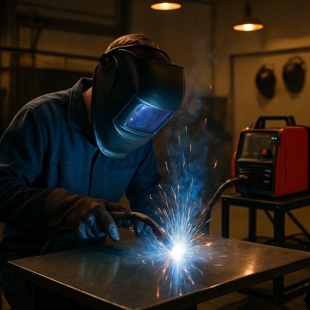
What Is MIG Welding? Start Cleaner Beads With Less Guesswork
What Is MIG Welding?
If you searched what is mig welding, the short answer is simple. MIG welding is a wire-feed welding process that uses an electric arc and shielding gas to join metal. In everyday shop talk, most people say MIG, while the broader technical name is GMAW, or gas metal arc welding, as described by WIA and M&M Certified Welding. That difference matters, because the casual name is common, but the formal term becomes important once gases, wires, and process variations enter the picture.
What MIG Welding Means in Plain English
MIG welding is the common name for a GMAW process that continuously feeds wire into an electric arc while shielding gas protects the weld pool.
That is the plain-language mig welding definition many beginners need first. It also clears up a common search query. When someone types "mig welder what is" or asks "what is a mig welder," they usually mean the machine used for this process, not a separate welding method. The mig welding meaning is straightforward: the machine feeds wire for you, the arc melts that wire, and the molten metal joins the parts together.
- Fast welding speeds for efficient work
- Continuous wire feeding that feels easier to manage
- Cleaner welds with less cleanup and often less slag than some other methods
- Beginner-friendly operation on many common fabrication jobs
Why This Process Is So Common
MIG is widely used because it blends speed, versatility, and accessibility. The process is common in fabrication and manufacturing, and it is also one of the easier entry points for new welders. Guidance from Bernard and Tregaskiss highlights those same strengths: ease of use, versatility, and productivity. That combination is why this process shows up everywhere from repair work to production welding.
This guide will keep the explanation simple without stopping at half-right definitions. You will get the basic theory, the correct terminology, and the practical setup context that helps the process make sense at the machine. And that is where the small naming gap between MIG and GMAW starts to matter more than most beginners expect.
What Is GMAW Welding?
That naming gap matters more than it first seems. In technical references such as Haynes, GMAW is the formal umbrella term for the wire-feed process many people casually call MIG. So if you are asking what is gmaw welding, the short answer is this: it is the technical name for the same general process most shops call MIG. If you are wondering what does mig stand for in welding, the traditional expansion is metal inert gas welding, and that older name still shows up constantly in everyday conversation.
MIG vs GMAW vs MAG Explained Simply
In plain English, MIG is the common shop label, GMAW is the textbook label, and mag welding is a term used in some technical or regional discussions when active shielding gases are part of the process. In real shop talk, many people still say MIG for all of it. That is why mig and mag welding can look like separate topics when they are really closely related naming systems around wire-feed arc welding.
| Process name | Shielding approach | Typical use | Shop term vs textbook term |
|---|---|---|---|
| MIG | Usually solid wire with external shielding gas | Fast, clean fabrication on common metals | Common everyday term in shops |
| GMAW | Consumable wire electrode with shielding gas | Manual, semi-automatic, or automatic welding with higher deposition rates | Formal technical umbrella term |
| MAG | Wire-feed process discussed with active gas language | Often treated as a terminology distinction rather than a different machine | Seen more in technical naming systems than casual U.S. shop talk |
| Gas-shielded FCAW | Flux-cored wire plus external shielding gas | Thicker metals and out-of-position work | Not true gas-shielded MIG, even though both use wire feed |
| Self-shielded FCAW | No external gas, shielding comes from the wire | Outdoor and windy work, portable repairs | Often called flux core, not MIG |
A beginner-friendly distinction from Miller helps here: solid-wire MIG uses a gas bottle, while flux-cored arc welding can be gas-shielded or self-shielded and leaves slag. They are related wire processes, but they are not interchangeable.
Transfer Modes Without the Confusion
Another term that trips people up is transfer mode. It simply describes how molten metal moves from the wire into the weld pool. Haynes breaks GMAW into four plain-language patterns:
- Short-circuit: Low heat, small controllable puddle, useful on thin sections and out-of-position work, but easier to get incomplete fusion on thicker joints.
- Globular: Large, irregular drops with less consistent penetration and bead shape, so it is seldom the preferred mode.
- Spray: A stream of small droplets with high heat input and high deposition, best suited to thicker material in the flat position.
- Pulsed spray: A controlled version of spray that lowers average heat input and spatter while staying useful across more positions and thickness ranges.
So when someone says they are "doing MIG," they may be using the everyday name for GMAW, and the real differences may come from the wire type, shielding method, and transfer mode. Those details sound technical on paper, but they are exactly what shape the arc once your finger hits the trigger.
How Does MIG Welding Work at the Machine?
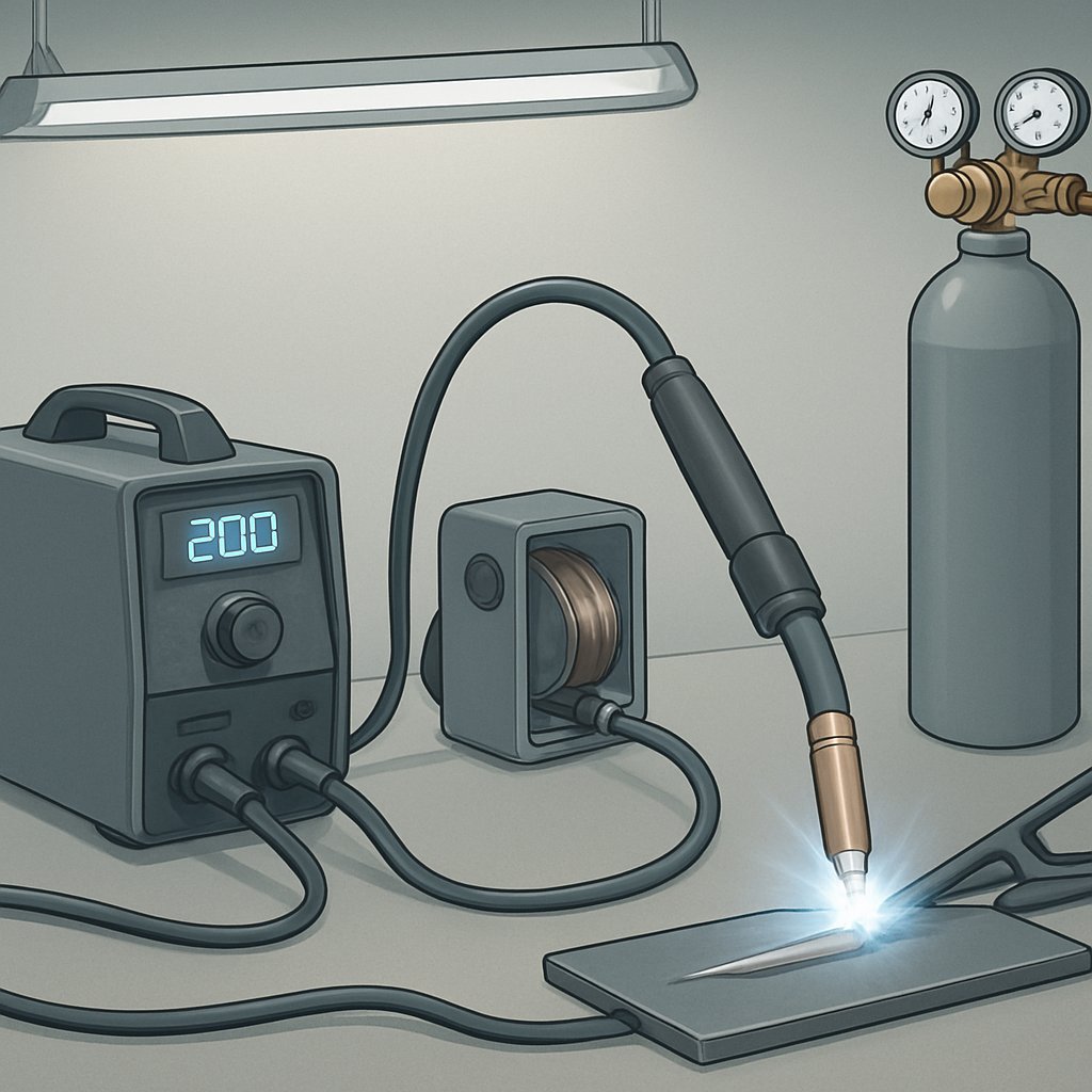
Transfer modes sound much less abstract when you picture the machine in motion. If you are asking how does mig welding work, the short answer is this: the welder feeds wire, sends current through that wire, and covers the weld area with shielding gas. A practical parts breakdown shows the path clearly: the power source, wire feeder, gun, gas system, and work clamp operate as one connected setup. For anyone still wondering how does welding work in shop terms, MIG is really a controlled combination of electricity, moving wire, and gas protection.
How the Arc Wire and Gas Work Together
When you pull the trigger, the machine starts feeding a continuous wire electrode through the gun. That wire does two jobs at once. It carries current to create the arc, and it becomes filler metal as it melts into the joint. The power source supplies the electrical energy, the work clamp completes the circuit through the workpiece, and the arc creates the heat that melts both the wire and the joint edges. At the same time, shielding gas flows through the gun and over the weld area. Guidance in this shielding gas guide emphasizes that gas coverage protects the molten weld pool from contamination from the moment the arc is struck.
- You press the trigger on the gun.
- Drive rolls pull wire from the spool and push it through the liner to the contact tip.
- Current reaches the wire, and an arc forms between the wire and the workpiece.
- The wire melts, the joint edges heat up, and a weld puddle forms.
- Shielding gas surrounds that puddle to help keep air away from the molten metal.
- As the gun moves forward, the puddle cools behind the arc and solidifies into a weld bead.
That is the mig welding process in its practical form, and it is also the heart of the broader gmaw welding process. If you have been asking how does a mig welder work, think of it as a feed system, an electrical circuit, and a gas shield all working at the same time.
The Main Parts of a MIG Welding Setup
- Power source: Supplies the current needed to start and sustain the arc.
- Wire spool: Holds the consumable wire that becomes both electrode and filler metal.
- Drive rolls and wire feeder: Control how smoothly wire reaches the gun, which affects arc stability and consistency.
- Gun and trigger: Let you direct the wire and start the weld where you need it.
- Contact tip: Transfers welding current to the wire for a steady arc.
- Nozzle: Directs shielding gas over the weld pool, influencing cleanliness and spatter control.
- Gas regulator and cylinder: Control gas delivery and coverage.
- Work clamp: Completes the electrical circuit through the workpiece.
Once you can picture how mig welding works at the gun, arc behavior stops feeling random. Bead shape, spatter, and weld appearance change when wire feed, gas coverage, and metal type change. That is why the next decisions, especially gas and filler wire selection, have such a direct effect on results.
What Gas Is Used for MIG Welding?
Arc stability can change fast when you swap consumables. That is why one of the first practical questions after learning how the process works is what gas is used for MIG welding. Shielding gas protects the molten weld puddle from atmospheric contaminants, and without that protection the weld can become weak and porous. It also changes spatter level, arc stability, arc performance, and bead appearance. So when beginners ask what gas does a mig welder use, the honest answer is not one universal bottle. The right choice depends on the base metal and the result you want.
Choosing Shielding Gas by Metal Type
If you are asking what gas for mig welding, start with the metal in front of you. A practical Miller gas guide breaks the common choices into mild steel, stainless steel, and aluminum, and each group behaves differently. That is also why choosing gas for a mig welder is really a welding-performance decision, not a minor accessory choice.
| Base metal | Common shielding gas direction | Filler wire direction | What changes in the weld |
|---|---|---|---|
| Mild steel | 75% argon/25% CO2 is very common. 100% CO2 is a lower-cost option. 90% argon/10% CO2 is less common for DIY use and is a good option for spray transfer on thicker plate. | Solid steel wire | 75/25 offers minimal spatter, good arc characteristics, and a bead that washes out well at the toes. 100% CO2 tends to create more spatter and a slightly erratic arc. |
| Stainless steel | Traditional short-circuit setups often use a helium trimix of 90% helium/7.5% argon/2.5% CO2. Another documented option is 98% argon/2% CO2 on compatible setups. Too much CO2 should be avoided. | Stainless-steel wire | Helium-containing gas helps the puddle wash out and supports deep penetration, arc stability, and strong bead characteristics. Low-CO2 argon blends can provide good bead profile and wetting. Excess CO2 can contribute to porosity or other defects. |
| Aluminum | 100% argon is the most common choice. Helium/argon blends can also be used. CO2 should be avoided because it can contaminate the weld. | Aluminum wire | 100% argon supports easy spray or pulsed spray transfer. Helium blends can work well but usually cost more. Aluminum is highly sensitive to contamination, so gas quality matters a lot. |
Shielding gas and filler wire are not extras. They are core process variables that directly affect penetration, spatter, and weld cleanliness.
Matching Filler Wire to Steel Stainless and Aluminum
The wire has to match the base metal just as carefully as the gas does. For mild steel, welders commonly use solid steel wire. For stainless, they use stainless-steel wire. For aluminum, they use aluminum wire. In a wire MIG setup, that match matters because the wire is doing two jobs at once: it carries current as the electrode and becomes filler metal as it melts into the joint.
That is why gas for mig welding and wire choice should always be considered together. For example, argon gas for mig welding is the standard starting point for aluminum, but that does not mean argon is automatically the best answer for mild steel or stainless. The puddle, arc feel, and finished bead all shift when either variable changes. Once the metal, gas, and wire are paired correctly, the machine itself becomes much easier to set up with confidence.
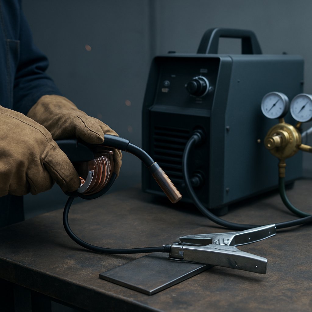
How to Set Up a MIG Welder Before Welding
Good gas and wire choices only pay off when the machine is prepared correctly. Whether you are using a compact metal inert gas welding machine for home projects or a larger GMAW welding machine in a shop, the basics stay the same: clean metal, correct wire path, proper gas flow, and correct polarity. Read the manual for your specific mig welder power source first, because controls and connection points vary by model. Still, the beginner workflow is very consistent.
Step by Step MIG Welder Setup
- Clean the joint and clamp area. Solid MIG wire does not handle rust, oil, paint, or dirt very well, so clean to bare metal and give the work clamp a clean contact point, as shown in this Miller setup guide.
- Inspect cables and consumables. Check that leads are tight, the gun is in good shape, and the contact tip and liner are not badly worn.
- Confirm mig welding polarity. For solid-wire MIG, standard setup is DCEP, or electrode positive. Self-shielded flux-cored welding uses DCEN. Both Miller and YesWelder outline that difference clearly.
- Match the drive roll to the wire. YesWelder notes that V-groove rolls are used for solid wire and W-groove rolls for flux-cored wire. Match the groove to the wire diameter as well.
- Load the spool correctly. Install the wire so it unwinds from underneath into the drive system, not over the top. Hold the wire firmly so it does not spring loose and tangle.
- Set spool and drive-roll tension. Too much or too little tension can cause poor feeding, so adjust to the owner’s manual rather than guessing.
- Connect the gas bottle and regulator. Attach the regulator carefully, connect the hose, open the cylinder, and set shielding gas flow. Miller recommends 20 to 25 cubic feet per hour for a common starting range.
- Attach the work clamp. Put it on clean metal and make sure the electrical path is solid.
- Test wire feed and gas flow. Point the gun safely away from the work and pull the trigger to confirm smooth feeding and gas delivery.
- Run a practice bead on scrap. Use the chart inside the machine door or the manual before touching your real project.
How Settings Affect Arc Stability and Bead Shape
On a constant-voltage MIG welding power source, wire feed speed largely controls amperage, while voltage affects arc length and bead shape. A second Miller parameter guide gives a useful starting rule: about 1 amp for every .001 inch of material thickness. That same source lists common wire ranges of .023 inch for about 30 to 130 amps, .030 inch for 40 to 145 amps, .035 inch for 50 to 180 amps, and .045 inch for 75 to 250 amps.
In practical terms, more wire feed usually means more deposition and more heat potential. More voltage usually flattens and widens the bead. If the arc stubs into the work, voltage may be too low. If it becomes erratic and seems to burn back toward the tip, voltage may be too high. Even a good MIG welding power source cannot make up for wrong polarity, poor gas coverage, or mismatched wire size.
| Material and thickness | Starter wire direction | Starter gas direction | Setup notes |
|---|---|---|---|
| Mild steel, thin sheet up to about 1/8 in | .023 in for very thin material, .030 in for general work | 75% argon / 25% CO2 | Good all-purpose choice with less spatter and less burn-through risk than straight CO2 |
| Mild steel, thicker sections | .035 in, or .045 in if machine output allows | 75/25 or 100% CO2 | 100% CO2 gives deeper penetration but more spatter and a rougher bead |
| Stainless steel, light to moderate sections | Stainless solid wire, commonly .035 in on smaller machines | Trimix such as 90% helium / 7.5% argon / 2.5% CO2 | Keep material very clean and use the machine chart for final tuning |
| Aluminum, light to moderate sections | Aluminum wire, often .030 in or .035 in | 100% argon | A spool gun is often preferred to reduce wire feeding problems |
When the machine feeds smoothly, the gas is steady, and the arc starts to sound right on scrap, the mystery shifts away from the box itself. What the bead looks like next depends heavily on how you hold the gun, how far the wire sticks out, and what you notice in the puddle while moving.
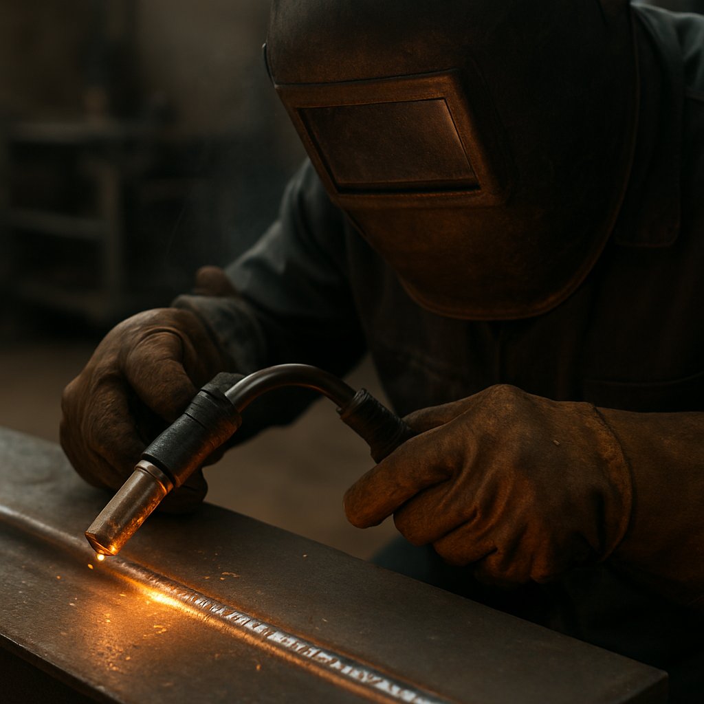
How to Weld With a MIG Welder
A machine can be set correctly and still produce a messy weld if the gun is moving poorly. This is where mig welding basics become body position and hand control. Stand in a balanced stance, support your hands, wrists, forearms, or elbows when you can, and use a two-handed grip if the joint allows. That extra support helps smooth out small wobbles, a practical point reinforced in the Miller beginner guide. If you are learning how to use a mig welder, think less about forcing the puddle and more about guiding it.
Running Your First MIG Bead
Start by aiming the gun correctly, then let the puddle tell you how fast to move. For a butt joint, a 90 degree work angle is a solid starting point. For a fillet weld, 45 degrees is common. A slight travel angle of about 15 degrees works well for many beginner passes. Keep stickout steady too. A typical stickout is around 3/8 inch, and stretching it much farther reduces heat input and can compromise gas coverage, as noted by Miller.
- Keep your shoulders and feet stable so the gun moves in one smooth line.
- Hold a consistent stickout instead of letting the wire drift closer and farther from the work.
- Watch the leading edge of the puddle, not just the bright arc.
- Pause just enough to establish the puddle, then move before the bead piles up.
- Use the trigger smoothly and avoid jerky starts that disturb the bead shape.
- Try to keep the arc riding on the front edge of the puddle as you travel.
That sequence is the heart of how to weld with a mig welder. Travel too slowly and the bead gets oversized. Move too fast and penetration and tie-in suffer. Good mig welding techniques are usually small acts of consistency repeated well.
Reading Weld Appearance as You Move
When welding with a mig welder, the bead is constant feedback. Watch its width, crown, and how the toes blend into the base metal. A smoother bead usually means your motion, stickout, and settings are working together. Uneven ripples usually mean one of those variables is drifting. The visual examples in this Miller defect guide are useful because they tie bead shape to what changed at the gun.
| Bead appearance | What it tends to indicate |
|---|---|
| Smoother, slightly crowned bead | Steady travel speed, better puddle control, and more consistent tie-in |
| Undercut along the edge | The bead is not filling the edge well, so review angle, speed, and settings |
| Excessive convexity | Too much buildup, often linked to slow travel or insufficient overall balance in settings |
| Irregular ripple pattern | Inconsistent hand movement, changing stickout, or unstable arc behavior |
Thin material raises the stakes. Welding sheet metal with mig welder takes more restraint than welding thicker steel because heat builds quickly and distortion shows fast. Short welds, tack spacing, and cooling pauses help control burn-through. Copper backing bars can also absorb excess heat, a practical idea echoed in this sheet metal guide. If you are practicing how to use a mig welder on thin panels, focus on heat control before bead length.
The useful part is that bad welds rarely appear without warning. Shape, sound, spatter, and surface texture usually leave clues about what needs adjusting.
MIG Welding Troubleshooting for Beginner Defects
Even a decent first bead can fall apart when one variable drifts. A quick good weld vs bad weld check starts with what you can see and hear: pinholes, bead shape, tie-in at the toes, spatter level, and arc sound. Guidance from Miller and Lincoln Electric points to the same pattern: most defects come from gas coverage, parameters, technique, or wire delivery, not random machine behavior. With porosity welding, for example, the bead traps gas and leaves a pitted, hole-filled surface.
Common MIG Problems and What Causes Them
| Visible symptom | Likely causes | Practical adjustments |
|---|---|---|
| Pinholes or pores in the bead | Inadequate shielding gas coverage, drafts, dirty base metal, excessive gun angle, excessive stickout, wet or contaminated gas cylinder, leaks, or heavy spatter in the nozzle or diffuser | Check the full gas path, clean the joint, clean the nozzle, reduce stickout, block drafts, inspect hoses and fittings, and use a push technique if gas coverage is being disturbed |
| Heavy spatter around the weld | Dirty metal or rusty wire, improper voltage, excessive stickout, insufficient gas coverage, worn or wrong-size contact tip, or incorrect polarity on flux-cored wire | Clean the base metal and wire, shorten stickout, inspect the tip and nozzle, verify polarity, and review travel speed and settings if spatter suddenly increases |
| Burn-through or holes in thin metal | Excessive heat and slow travel speed | Reduce voltage or wire feed speed as needed and move faster, especially on thin material |
| High, ropey bead with poor penetration or lack of fusion | Settings too cold, low heat input, wrong gun angle, or travel speed that keeps the arc off the leading edge of the puddle | Increase voltage or wire feed speed as needed, keep a shallow gun angle, and adjust travel so the arc stays on the front edge of the puddle |
| Chattering, erratic feeding, burnback, or inconsistent arc | Worn contact tip, dirty or wrong-size liner, worn drive rolls, poor drive-roll tension, reel coasting, or gun damage | Inspect and replace worn parts, clean or replace the liner, set proper drive-roll tension, and check spool brake and wire alignment |
| Arc sounds wrong | Voltage too high or too low | In short-circuit transfer, a steady buzz is normal. A steady hiss points high, while a loud raspy sound points low |
Most defects are repeatable patterns. The bead usually shows where setup and technique stopped matching each other.
How to Correct Weld Defects Step by Step
- Clean first. Oil, rust, paint, and grease are common troublemakers in both porosity and spatter.
- Check shielding gas before chasing exotic causes. If mig weld gas protection is disturbed by drafts, leaks, or a dirty nozzle, the weld pool gets contaminated fast. That is why beginners ask do mig welders need gas. For true gas-shielded MIG, yes. A mig welder and gas setup can still fail if coverage never reaches the puddle properly.
- Listen to the arc. The sound often tells you whether voltage is too high or too low before the bead fully confirms it.
- Inspect wire delivery. A worn tip, liner, or drive roll can make the machine feel unpredictable even when the settings are close.
- Change one thing at a time on scrap. Gas welding settings, travel speed, and stickout interact, so small test beads make diagnosis much easier.
That troubleshooting habit matters because recurring problems are not always just setup mistakes. Sometimes wind, dirty material, or the job itself keeps working against the process, and that is where process choice starts to matter as much as machine adjustment.
What Is MIG Welding Used For and When Is It Best?
Some weld problems do not start at the machine. They start with choosing the wrong process for the job. If you are still asking what is mig welding used for, think clean indoor fabrication first. MIG is widely chosen for general shop work, auto repair, brackets, frames, and repeated welds where speed, easy wire feeding, and low cleanup matter. A practical comparison guide places MIG on the easy end of the learning curve and highlights its strong fit for fast production and general fabrication.
When MIG Welding Is the Best Fit
MIG works best when the metal is clean, the setup is protected from wind, and you want a process that moves quickly without leaving slag behind. So, what is a mig welder used for in real-world terms? Mostly clean shop welding on mild steel, stainless steel, and, with the right setup, aluminum. That last point matters because many beginners ask, can you mig weld stainless steel. Yes, you can, provided the wire and shielding gas match the material.
The difference between TIG and MIG welding becomes simple when you compare priorities. TIG gives finer control and a more cosmetic result, but it is slower and harder to master. MIG usually makes more sense when productivity matters more than ultra-precise puddle control. If you need a welder for aluminum, MIG can also work, though aluminum is less forgiving than mild steel and often benefits from the setup advice noted in this aluminum guide.
When Another Welding Process Makes More Sense
| Process | Learning curve | Best material condition | Indoor or outdoor | Weld appearance | Production speed | Best fit |
|---|---|---|---|---|---|---|
| MIG | Easiest | Clean, well-prepped metal | Best indoors | Clean, little cleanup, little to no slag | High | General fabrication, auto work, thin to medium sections |
| TIG | Hardest | Clean metal, thin or critical parts | Mainly indoors | Best appearance and control | Slow | Precision work, thin materials, high cosmetic standards |
| Stick | Moderate | Rusty, dirty, or imperfect surfaces | Very good outdoors | Rougher finish, slag removal needed | Moderate | Repair, construction, field work, portability |
| Flux-cored | Moderate | Less-than-perfect surfaces, thicker material | Good outdoors, especially self-shielded | More spatter and slag than MIG | High | Structural steel, heavy fabrication, windy conditions |
In TIG MIG MAG welding comparisons, that split stays consistent. MIG and MAG stay on the wire-feed, production-friendly side. TIG moves toward precision. Stick and flux-cored take over when portability, dirty material tolerance, or outdoor work become more important than appearance. A flux-core comparison also notes that gas-shielded MIG is vulnerable to wind, while self-shielded flux-cored is far better suited to breezy job sites.
So MIG is often the smartest all-around shop choice, not the universal answer to every welding problem. Its real strength is clean, repeatable speed, which is exactly why it becomes even more valuable when work scales from one-off parts to full production.
How MIG Welding Fits Modern Manufacturing
Clean, repeatable speed matters even more when one part becomes a thousand. In production settings, mig welding often moves from a hand-held shop process to a programmed arc process built for throughput, fixture control, and traceability. The automotive overview from JR Automation describes gas metal arc welding as a core method for structural steels and aluminum, especially where robots can hold torch path, travel speed, and wire feed steady from part to part.
Where MIG Welding Fits in Modern Manufacturing
That matters on brackets, mounts, support beams, frames, and welded subassemblies, not just on small repair jobs. CNC Machines notes that robotic MIG and TIG welding are used to join support beams and integrated chassis features with consistent quality. In automotive plants, a body-in-white may involve 4,000 to 5,000 weld sites overall, plus 500 or more later in assembly, as outlined by JR Automation. Many of those are spot welds, but that scale explains why gmaw welding is valued anywhere a repeatable bead weld is needed on structural parts. At this level, gas metal arc welding equipment is more than a power source and torch. It usually sits inside a larger cell with fixtures, robots, seam tracking, and parameter logging. That is also where gas metal arc welding aluminum work and gmaw aluminum welding demand tighter control over wire feeding, heat input, and part fit-up.
What to Look for in a Production Welding Partner
When manufacturers outsource welded assemblies, the issue shifts from basic welding ability to repeatable welding performance. The supplier guidance summarized by Quality Digest emphasizes capability, conformance to requirements, on-time delivery, and support. For chassis work, a useful checklist looks like this:
- Documented process control for gas metal arc welding, including parameter consistency and inspection records
- Robotic capability for repeatable bead geometry on brackets, frames, and other assemblies
- Experience across steel and aluminum, especially where gas metal arc welding aluminum applications are involved
- Quality systems and traceability suited to automotive expectations
- Ability to handle both prototype builds and production volumes
- Clear communication on lead times, part changes, and corrective action
A practical example is Shaoyi Metal Technology, which applies advanced robotic welding lines and an IATF 16949 certified quality system to high-performance chassis parts for steel, aluminum, and other metals. That kind of setup shows what industrial MIG looks like when repeatability, speed, and weld quality all have to hold at production scale.
MIG Welding FAQs
1. What does MIG stand for in welding?
MIG stands for metal inert gas. In everyday use, that is the name most people apply to the broader GMAW wire-feed welding process. Even when gas blends are involved, welders still commonly say MIG because it is the simpler shop term.
2. Is MIG welding the same as GMAW?
They are usually referring to the same basic process, but the wording is slightly different. GMAW is the formal technical name, while MIG is the common label used in shops, product pages, and beginner guides. Knowing both terms helps when you compare gases, transfer modes, or machine settings.
3. What gas does a MIG welder use?
The gas depends on the metal being welded. Mild steel often uses an argon and CO2 blend or straight CO2, stainless uses blends suited to stainless filler wire, and aluminum usually runs with argon. Gas choice affects more than protection, because it also changes arc feel, spatter level, and bead appearance.
4. Is MIG welding good for beginners?
Yes, MIG is often one of the easiest entry points into arc welding because the wire feeds continuously and the process is fast to learn on clean material. It still rewards good habits, such as steady stickout, clean joint prep, correct polarity, and proper travel speed, but many new welders find it more approachable than TIG.
5. What is MIG welding used for?
MIG welding is widely used for fabrication, repair work, sheet metal, brackets, frames, and repeatable welds on steel, stainless, and aluminum with the right setup. It also scales well into manufacturing, where robotic systems can produce consistent welds on assemblies and chassis parts. For example, Shaoyi Metal Technology applies robotic welding and an IATF 16949 quality system for high-precision automotive chassis components.