 Small batches, high standards. Our rapid prototyping service makes validation faster and easier —

Key Principles of Trimming and Piercing Die Design
TL;DR
Trimming and piercing die design is a specialized engineering discipline focused on creating robust press tools for the precise cutting and punching of sheet metal. Success hinges on accurate calculations for cutting forces, strategic selection of tool materials, and advanced design techniques. The primary goals are to manage material stress effectively, ensure clean cuts with minimal burrs, and maximize the operational life and accuracy of the die set.
Fundamentals of Trimming and Piercing Operations
In the world of sheet metal fabrication, trimming and piercing are foundational cutting operations that define a part's final geometry. While often grouped with similar processes, they serve distinct functions. Trimming is the process of removing excess material from the outer edge of a stamped part to achieve its final profile. Piercing, on the other hand, involves creating internal features like holes or slots by punching out material from within the part's perimeter. Both operations rely on a shearing action, where extreme stress is concentrated along the cutting edges of a punch and die, causing the material to fracture cleanly.
The quality of a mechanically cut edge is characterized by four zones: rollover, burnish, fracture, and burr. As detailed in guides from AHSS Guidelines, the ideal edge for high-strength steels features a distinct burnish zone and a smooth fracture zone, which is crucial for preventing cracks in subsequent forming operations. Understanding these fundamentals is the first step toward designing a tool that produces consistent, high-quality components.
To clarify their roles, it's helpful to compare these operations with other common cutting processes. Blanking is similar to piercing, but the material punched out (the slug) is the desired part, whereas in piercing the slug is scrap. Shearing is a more general term for cutting sheet metal in a straight line between two blades. Each process is chosen based on the desired outcome and its place within the manufacturing sequence.
| Operation | Description | Primary Goal | Resulting Material |
|---|---|---|---|
| Trimming | Cuts excess material from the perimeter of a pre-formed part. | Achieve final outer contour. | The removed material is scrap. |
| Piercing | Punches holes or slots within the part's boundary. | Create internal features. | The punched-out slug is scrap. |
| Blanking | Cuts a shape from the sheet, where the cutout is the desired part. | Produce a flat part from stock. | The cutout (blank) is the part. |
| Shearing | Makes long, straight cuts to separate pieces of sheet metal. | Size stock or create straight edges. | Both pieces can be usable stock. |
Core Principles of Die Design and Key Calculations
Effective die design is a data-driven process grounded in engineering principles. Before any modeling begins, designers must perform critical calculations to ensure the tool can withstand operational forces and function reliably within the selected press. The most fundamental calculation is for cutting force, which determines the tonnage required from the press. The formula is generally expressed as: Cutting Force (F) = L × t × S, where 'L' is the total length of the cut perimeter, 't' is the material thickness, and 'S' is the material's shear strength.
Accurately determining the cutting force is essential for selecting a press with adequate tonnage, typically with a 20-30% safety margin. Another critical factor is the die clearance—the gap between the punch and the die opening. As outlined in a comprehensive guide by JEELIX, optimal clearance is typically 5-12% of material thickness per side. Insufficient clearance increases cutting force and tool wear, while excessive clearance can lead to large burrs and a poor-quality edge. For advanced high-strength steels (AHSS), these clearances often need to be increased to manage the higher stresses involved.
Material selection for the die components themselves is another core principle. Punches and die inserts must possess a balance of hardness for wear resistance and toughness to prevent chipping under impact. Common choices include D2 and A2 tool steels for general applications, while high-volume production or work with abrasive materials may require powder metallurgy steels or carbide. The selection process involves a trade-off between cost and performance, aiming to maximize the die's lifespan and minimize maintenance downtime. For complex applications, such as in the automotive sector, seeking expertise is crucial. Companies like Shaoyi (Ningbo) Metal Technology Co., Ltd. specialize in automotive stamping dies, leveraging advanced simulations and materials knowledge to deliver robust and efficient tooling solutions.
| Material | Shear Strength (MPa) | Shear Strength (PSI) |
|---|---|---|
| Mild Steel (Low Carbon) | 345 | 50,000 |
| Aluminum Alloy (6061-T6) | 207 | 30,000 |
| Stainless Steel (304) | ~386 | ~56,000 |
| DP600 Steel | ~450 | ~65,000 |
Anatomy of a Trimming and Piercing Die Set
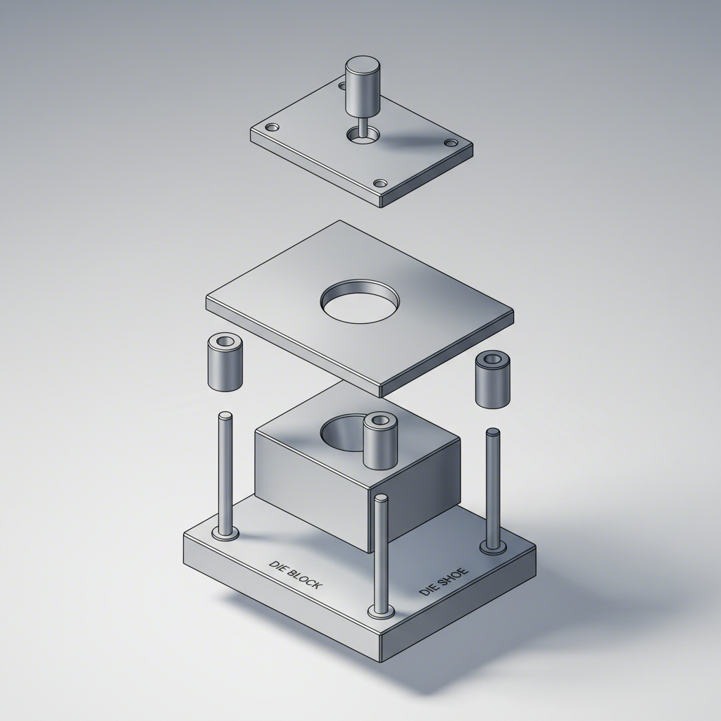
A die is not a monolithic block of steel but a precision assembly of interdependent components, each with a specific function. Understanding this anatomy is key to designing, building, and maintaining effective tooling. The entire assembly is housed within a die set, which consists of an upper and lower die shoe (or plate) aligned by guide pins and bushings. This foundational system ensures micron-level alignment between the upper and lower halves of the tool during high-speed operation, which is critical for preventing damage and maintaining part consistency.
The primary working components are the punch and the die block (or die button/insert). The punch, mounted to the upper die shoe, is the male component that performs the cutting. The die block, mounted to the lower shoe, is the female component with an opening that the punch enters. The precise geometry and clearance between these two parts define the final shape of the pierced hole or trimmed edge. Their material, hardness, and surface finish are paramount to tool life and part quality.
Another crucial component is the stripper. After a punch cuts through the material, the sheet metal's elastic recovery causes it to cling to the punch. The stripper's function is to forcibly remove the material from the punch on the press's upstroke. Strippers can be fixed or spring-loaded, with the latter providing pressure to hold the material flat during the cutting operation, thereby improving part flatness. For progressive dies, pilots are also essential. These are pins that engage with previously pierced holes in the strip to ensure precise alignment at each subsequent station.
Maintenance Checklist for Die Components:
- Punches and Die Buttons: Regularly inspect cutting edges for rounding, chipping, or excessive wear. Sharpen as needed to maintain a clean cut and reduce cutting force.
- Guide Pins and Bushings: Ensure they are properly lubricated and check for signs of galling or wear. Worn guides can lead to misalignment and catastrophic die crashes.
- Stripper Plate: Verify that springs (if applicable) have adequate pressure and are not broken. Check for wear on the contact surface.
- Die Set: Inspect the die shoes for any cracks or damage. Ensure all fasteners are torqued to the correct specification.
- General Cleanliness: Keep the die free of slugs, slivers, and other debris that can cause part defects or damage to the tooling.
Advanced Die Design Techniques and Materials
Moving beyond basic principles, advanced die design focuses on optimizing performance, handling difficult materials, and extending tool life for high-volume production. One of the most significant advancements is the use of progressive dies, which perform multiple operations (e.g., piercing, trimming, bending) sequentially at different stations within a single tool. As explained by experts at Eigen Engineering, mastering progressive die design involves sophisticated strip layout planning to maximize material usage and ensure strip stability as it advances through the die.
For achieving exceptional part flatness, techniques like fineblanking and cut-and-carry are employed. Fineblanking is a specialized process that uses a high-pressure pad and a v-ring to clamp the material tightly, resulting in a fully sheared, straight-edged part with virtually no fracture zone. Similarly, the cut-and-carry method, detailed by The Fabricator, involves blanking the part partially through the strip and holding it flat with a pressure pad before it is ejected at a later station. This control over the material during cutting minimizes the internal stresses that cause distortion.
Designing for advanced high-strength steels (AHSS) presents unique challenges due to their high strength and reduced ductility. This requires larger die clearances, more robust tool structures, and premium tool materials like powder metallurgy steels or carbide to withstand the extreme forces and abrasive wear. Additionally, punch geometry can be modified to reduce peak tonnage and shock. Using a sheared or beveled punch face staggers the cutting action over a slightly longer duration, which significantly lowers the required force and reduces the violent "snap-through" effect that can damage both the die and the press.
Progressive Dies vs. Single-Station Dies
- Pros of Progressive Dies: Extremely high production speed, reduced labor costs, high repeatability, and consolidation of multiple operations into one tool.
- Cons of Progressive Dies: Very high initial tooling cost, complex design and build process, and less flexibility for large or deeply drawn parts.
- Pros of Single-Station Dies: Lower tooling cost, simpler design, and greater flexibility for low-volume runs or very large parts.
- Cons of Single-Station Dies: Much slower production speed, higher labor costs per part, and potential for inconsistencies due to repeated handling and positioning.

Frequently Asked Questions
1. What is the die design rule?
While there isn't one single "rule," die design follows a set of established principles. These include calculating cutting forces based on material properties, establishing proper punch-to-die clearance (typically 5-12% of material thickness per side), ensuring structural rigidity of the die set, and planning a logical sequence of operations in the strip layout. The overarching goal is to create a tool that is safe, reliable, and produces parts that consistently meet quality specifications.
2. What is the trim tool die casting?
A trim tool in die casting serves a similar purpose to one in sheet metal stamping but operates on a different type of part. After a part is created through die casting (injecting molten metal into a mold), it is left with excess material such as the runner, overflows, and flash. A trim die is a tool used in a secondary press operation to shear off this unwanted material, leaving a clean, finished cast part.
3. What is the steel rule for die cutting?
Steel rule die cutting is a different process typically used for softer materials like paper, cardboard, foam, or thin plastics. It involves pressing a sharp, thin steel blade (the "steel rule"), which has been bent into the desired shape and embedded in a flat base (often plywood), into the material. It is a cost-effective method for cutting shapes in non-metallic or very thin sheet metal applications.
4. What are the different types of die cutting?
Die cutting encompasses several methods tailored to different materials and production volumes. In sheet metal, this primarily refers to stamping operations like piercing, blanking, and trimming using hard tooling (punch and die sets). Other forms include flatbed die cutting (for thicker materials), rotary die cutting (for high-speed production of labels or gaskets), and digital cutting methods like laser or waterjet cutting, which use no physical die.