 Small batches, high standards. Our rapid prototyping service makes validation faster and easier —

Stamping Manufacturing Process In 9 Steps: From DFM To SPC
Step 1: Define Project Requirements and DFM Goals for Stamping Manufacturing Success
Ever wondered why some stamped parts fit perfectly while others cause costly setbacks? The answer often lies in how clearly the project requirements are defined at the very start of the stamping manufacturing process. Launching your manufacturing stamping process with a rock-solid foundation ensures every downstream decision supports fit, form, function, and cost. Let’s break down how to get it right from the beginning.
Define Critical-To-Quality Features
Imagine you’re assembling a high-precision product. Which features absolutely must meet tight tolerances? Identifying these critical-to-quality (CTQ) features—such as hole locations, flatness, or edge conditions—ensures your stamping process is dialed in where it matters most. Early definition of CTQs helps prevent surprises during production and aligns the team on what success looks like.
Set Volume, Cost, and Lead-Time Targets
Are you planning a short-run prototype or a multi-year production campaign? Clearly capturing the intended part volumes, target costs, and required lead times is essential. These factors influence everything from tool design to material selection and even inspection strategies. For example, high-volume runs may justify more robust tooling and automation, while low-volume jobs might prioritize flexibility and cost control.
Map Functional Surfaces and Datum Strategy
Where does the part interface with other components? Mapping out functional surfaces and establishing a logical datum strategy ensures that measurements reflect how the part will perform in its final assembly. This step is crucial for both quality and manufacturability in the stamping process in manufacturing. Remember, datums should be chosen based on assembly needs—not just for measurement convenience.
- Material family (steel, aluminum, etc.)
- Gauge range (thickness)
- Tolerances (critical and general)
- Finish or coating requirements
- Edge conditions and burr direction
- Cosmetic and safety zones
- Weld or assembly interfaces
- Packing and handling constraints
- Target Cp/Cpk (process capability)
- Required PPAP level (if applicable)
| Feature | Function | Datum Reference | Tolerance Type | Risk Level |
|---|---|---|---|---|
| Mounting Hole | Assembly alignment | A | Positional | High |
| Edge Flange | Structural support | B | Flatness | Medium |
| Cosmetic Face | Visible surface | C | Surface finish | Low |
Define datums aligned to product assembly, not just convenient measurement faces.
Execution Tips for a Flawless Start
- Request both the latest native CAD files and a neutral format (such as STEP or IGES) to avoid translation errors.
- Ask about any prior forming issues on similar parts—past challenges can inform risk mitigation.
- Document all assumptions and unknowns. These can be validated later through simulation and tryout phases.
By thoroughly capturing requirements up front, you’ll set the stage for a smoother, more predictable manufacturing stamping process. This approach not only reduces program risk but also accelerates tooling design and downstream approvals. If you’re still asking, “What is metal stamping and why does it demand so much upfront detail?”—it’s because every decision made here ripples through cost, quality, and delivery. Get it right, and the rest of your stamping process will follow.
Step 2: Select Materials and Gauge Strategically for Reliable Stamping Results
Ever found yourself overwhelmed by choices when it comes to picking the right metal for stamping? The truth is, the material you choose will shape everything from part performance to long-term costs. Let’s walk through how to make smart decisions about metal stamping materials and gauge, so your stamping manufacturing process delivers the results you expect.
Choose Material Family by Function
Imagine you’re designing a bracket for an automotive assembly. Should you reach for carbon steel, stainless steel, or perhaps consider aluminium stamping? Each material brings its own strengths and trade-offs. Here’s a quick comparison to help you weigh your options:
| Material Family | Typical Gauge Range | Formability | Springback Tendency | Surface/Coating Notes | Typical Applications |
|---|---|---|---|---|---|
| Low-Carbon Steel | 0.020"–0.250" | Excellent | Low | Can be galvanized or painted | Brackets, housings, general hardware |
| HSLA Steel | 0.030"–0.187" | Good | Moderate | Often coated for corrosion resistance | Automotive frames, structural parts |
| Stainless Steel | 0.015"–0.125" | Fair–Good | High | Excellent corrosion resistance; may require lubrication | Food equipment, medical, decorative parts |
| Aluminum Alloys | 0.016"–0.125" | Excellent | High | Can be anodized, powder coated, or painted | Electronics, automotive, aerospace, appliances |
Control Springback and Formability
When you bend or form metal, it doesn’t always stay exactly where you put it—this is called springback. For example, aluminium stamping often requires extra attention to springback management because aluminum alloys tend to "bounce back" more than steel. Stainless steel stamping can also be tricky due to work hardening and higher required forming forces. Here’s what to keep in mind:
- Aluminum: Plan for robust fixturing and possibly over-bending to compensate for springback. Grades like 5052 and 6061 combine good formability with strength, making them a popular choice for stamped aluminum parts in demanding applications.
- Stainless Steel: Use appropriate lubrication and consider the work hardening rate to avoid tool wear or cracking. Select grades like 304 or 430 for a balance of formability and corrosion resistance.
- HSLA and Carbon Steel: These materials are generally easier to form and control, especially for high-volume runs where consistency is critical.
Align Gauge With Press Capacity and Tolerance
Gauge selection isn’t just about thickness—it’s about matching the right metal for stamping with your press capabilities and part requirements. For instance, a thicker gauge offers more strength but may require a more powerful press and tighter process controls. Remember, gauge numbers are not universal—a 16-gauge aluminum sheet is thinner than a 16-gauge steel sheet, so always reference material-specific charts.
- For tight tolerances, choose a gauge that minimizes variation but stays within the press’s rated capacity.
- Consult suppliers for formability curves and thickness tolerances specific to your chosen material.
- Validate critical dimensions through prototype runs or tryout before committing to high-volume production.
Coating Compatibility Notes
- Galvanneal: Works well with low-carbon and HSLA steels for corrosion protection.
- Zinc: Common for steel parts needing a bright finish and extra protection.
- Anodizing: Ideal for stamped aluminum parts to boost corrosion resistance and surface hardness.
- E-coat/Powder Coat: Suitable for both steel and aluminum for enhanced durability and aesthetics.
By methodically weighing the function, formability, and finishing needs of your part, you’ll select the right combination of metal stamping materials and gauge. This foundational step in the stamping manufacturing process ensures your components meet performance targets and are cost-effective to produce. Up next, we’ll look at how to plan the process and select the right press for your chosen materials.
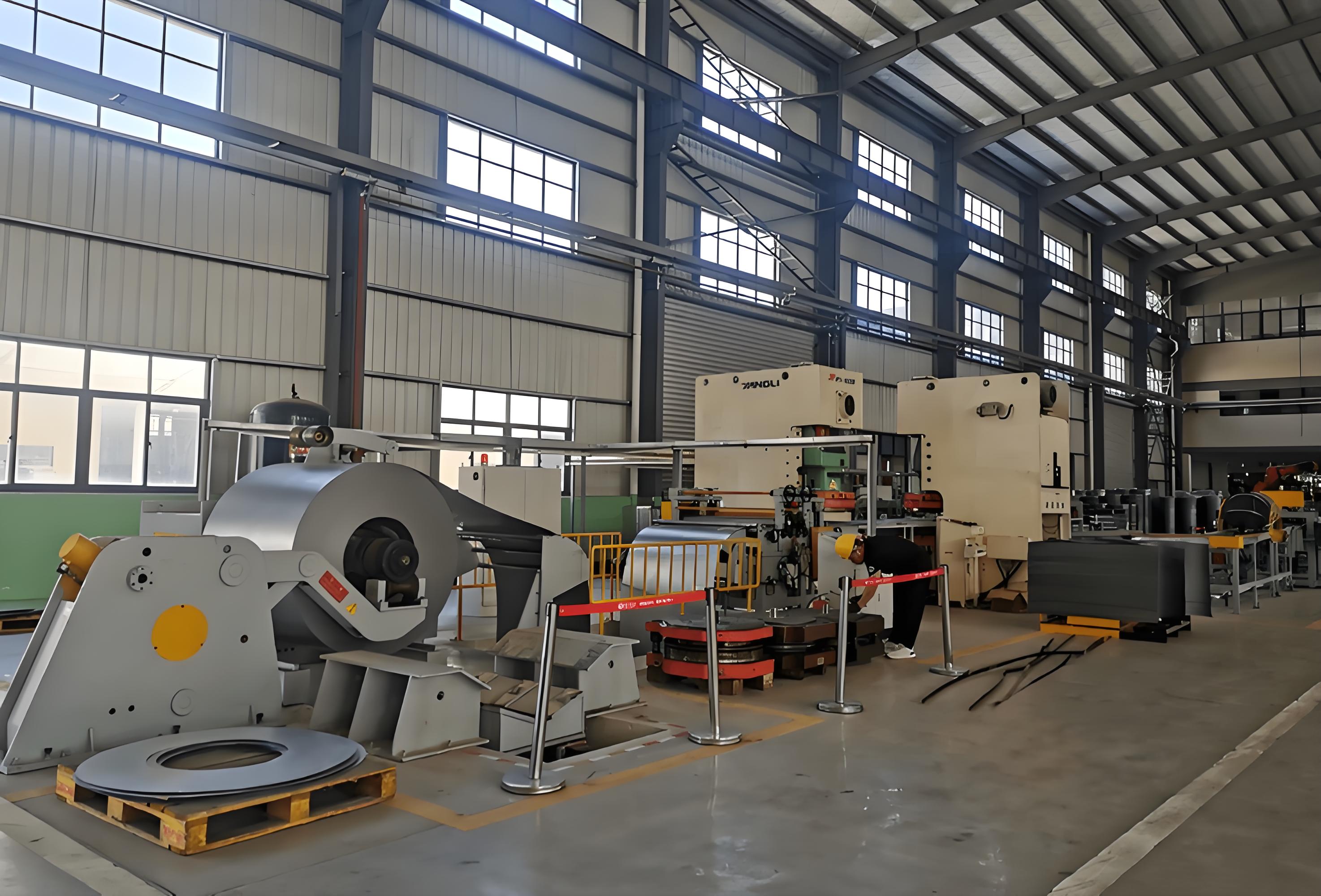
Step 3: Plan the Process and Choose the Right Stamping Press
When you’re ready to turn your material choice into real stamped parts, the next critical step in the stamping manufacturing process is architecting the production route and sizing the press line. Sounds complex? It doesn’t have to be—let’s break down how to match your operations to the right stamping presses and ensure your process runs smoothly from the first blank to the last finished part.
Estimate Press Tonnage and Bed Size
Before you even think about tooling, you’ll need to know how much force your sheet metal stamping press must deliver. Underestimating tonnage can stall your project; overestimating can waste budget and floor space. Here’s a practical way to estimate what you need:
-
Calculate Required Tonnage: Use the formula: Tonnage (T) = Perimeter (P) x Thickness (Th) x Material Constant (C). The material constant reflects the shear strength of your selected metal. For example, soft aluminum uses C = 11, cold-rolled steel uses C = 27, and stainless steel can be as high as 50.
- Example: For a 12-inch perimeter, 0.050" thick cold-rolled steel: 12 × 0.050 × 27 = 16.2 tons required.
- Determine Bed Size and Stroke: The bed must be large enough to fit your die, accounting for strip width and scrap clearance. Stroke length should accommodate the tallest part feature plus die height.
- Factor in Binder Force (for deep drawing): If your process includes forming or drawing, estimate binder force to prevent wrinkling—typically 20–50% of the main tonnage, depending on material and geometry.
Press selection is driven by the highest load station and the worst-case off-center loading.
Sequence Operations for Stability
Imagine your sheet metal press as a mini assembly line. Each station—blanking, piercing, forming, flanging, coining—needs to be sequenced so the strip stays stable and each operation is properly supported. Progressive die stamping is ideal for high-speed, high-volume runs with multiple operations in one pass, while transfer or line dies may be better for larger, more complex parts.
Here’s how a typical station-to-operation mapping might look:
| Station | Operation | Estimated Load (tons) | Sensoring | Lubrication Note | Scrap Route |
|---|---|---|---|---|---|
| 1 | Blanking | 20 | Strip feed, part-out | Light oil, pre-feed | Chute to bin |
| 2 | Piercing | 15 | Slug detection | Spot lube | Slug retention, ejection |
| 3 | Forming | 18 | Load cell | Continuous spray | Internal |
| 4 | Flanging | 10 | Part presence | Spot lube | Internal |
| 5 | Coining | 25 | Tonnage monitor | Final clean | Final ejection |
Plan Lubrication and Scrap Handling
Ever seen a press line grind to a halt because of jammed scrap? Planning for proper lubrication and scrap removal is just as important as sizing your metal stamping machine. Use the right lubricant for your material and operation—light oil for blanking, heavier lubricants for deep draws, and ensure even application. Design scrap chutes and slug retention to prevent double hits or die damage, and allocate sensors to detect misfeeds, part-outs, and excessive tonnage.
- Validate that off-center loads stay within the press’s rating curve—uneven force can damage both dies and presses.
- Ensure your sheet metal stamping press is compatible with your chosen process (progressive, transfer, or line die setups).
- Plan for feeder and straightener specs that match your coil or blank requirements.
By carefully mapping your operation sequence, estimating force and space needs, and planning for lubrication and scrap, you’ll set up a metal pressing process that is stable, efficient, and ready for consistent output. Next, we’ll dive into die design and tooling—where all this planning gets translated into precision hardware for your stamping process.
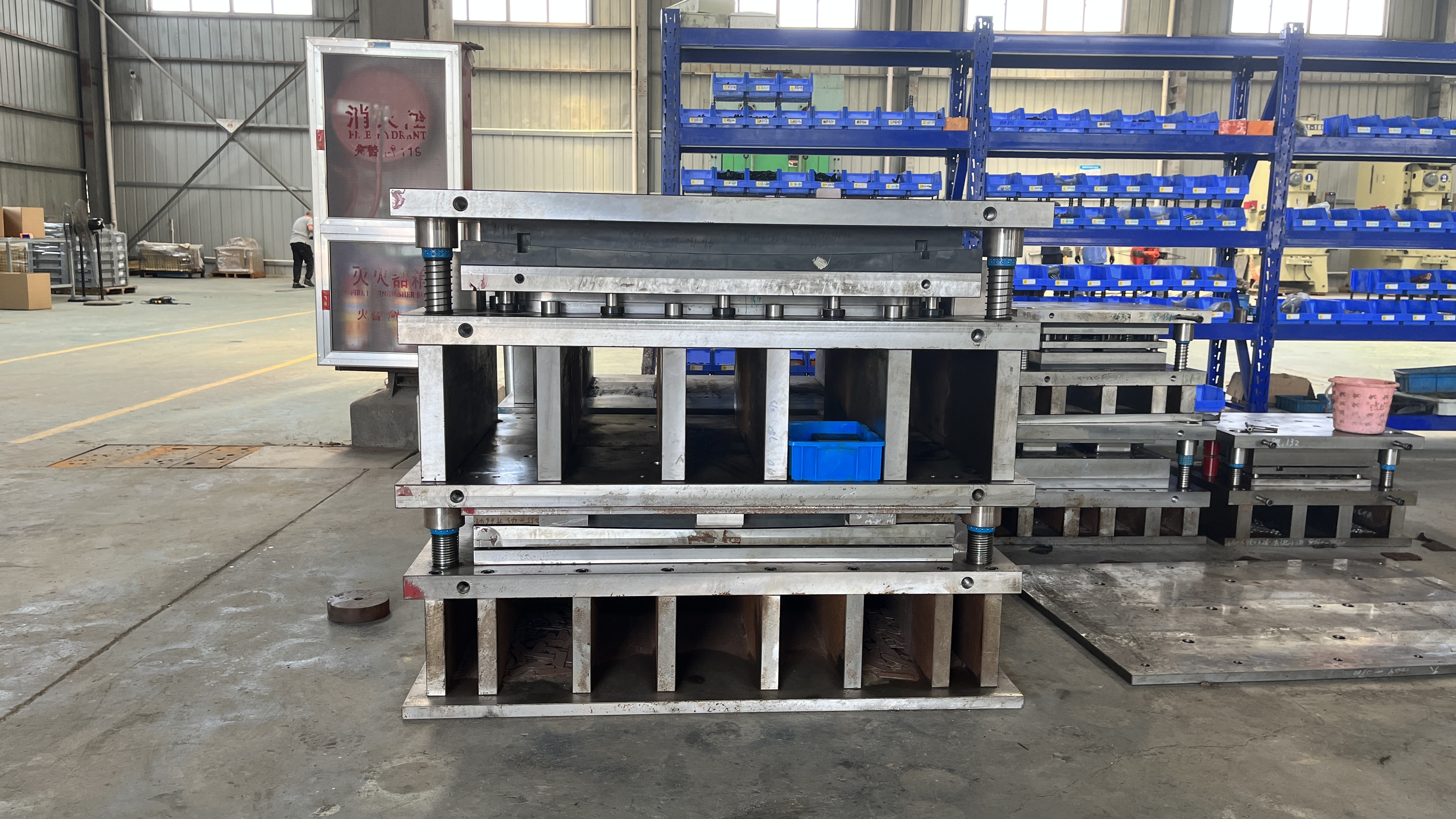
Step 4: Engineer the Die Design and Tooling Choices for Precision Stamping
When you picture a stamping manufacturing process that churns out flawless parts, what’s happening behind the scenes? The answer: a meticulously engineered die system, tailored to your part’s needs and production goals. Let’s walk through how to select the right types of stamping dies, set up critical clearances, and plan for long-term reliability—so your sheet metal die design delivers on every front.
Select the Right Die Type
Choosing a die isn’t just a technical step—it’s a strategic business move. The die type you select will shape your tooling investment, production speed, maintenance needs, and part quality. Here’s a side-by-side comparison to help clarify your options:
| Die Type | Best For | Complexity | Changeover Time | Expected Maintenance | Cost Trend |
|---|---|---|---|---|---|
| Progressive Die | High-volume, complex parts | High | Moderate | Frequent (multi-station) | High initial, low per-part |
| Compound Die | Simple, flat parts | Low | Short | Low | Low |
| Transfer Die | Large/intricate parts, multi-step forming | Very High | Long | Frequent (die & transfer system) | Very High |
For high-volume, intricate jobs, a progressive die is often the top choice. If you’re after simple, flat shapes in smaller runs, compound dies keep things cost-effective. And when your part is large or requires multiple forming steps, transfer dies offer unmatched flexibility. Each sheet metal die type comes with its own balance of speed, cost, and maintenance—so match the die to your real-world needs, not just the part drawing.
Set Punch-Die Clearances and Radii
Ever notice how some stamped parts have razor-sharp edges and others need deburring? It’s all about punch and die clearance. Proper clearance ensures clean cuts, minimizes burrs, and extends the life of your metal stamping dies. Here’s how to get it right:
- Material Matters: Harder, thicker materials need larger clearances. For most applications, a good starting point is 10% of the material thickness per side. For example, 0.060" steel calls for about 0.006" clearance per side. For tougher materials or longer tool life, 11–20% may be appropriate.
- Radii and Bend Design: Use an inside bend radius equal to or greater than the material thickness unless your design data supports tighter bends. This reduces cracking and increases die life.
- Critical Dimensions: Maintain minimum web widths and hole-to-edge distances to avoid weak spots and premature die wear. For instance, keep web widths at least 1.5x material thickness and hole-to-edge distances at least 2x thickness.
Use progressive pilots and keying to control strip growth and maintain positional accuracy.
Plan Maintenance and Insert Strategy
Imagine investing in a custom metal stamping die, only to face costly downtime from worn features. Proactive planning for maintenance and inserts can keep your line running smoothly:
- Removable Inserts: Design wear-prone features (like piercing punches or trim edges) as replaceable inserts. This allows for quick swaps without full die teardown.
- Die Steels and Treatments: Select tool steels to match your run volume and material. For general use, A2 or D2 are common; for high-wear or abrasive jobs, consider high-speed steel or even carbide for extreme longevity.
- Coatings: Where galling is a risk—especially with stainless or aluminum—specify coatings like TiN or DLC to reduce friction and wear.
- Preventive Maintenance: Schedule regular inspections and polishings, especially for progressive and transfer dies which have more moving parts.
Essential Design Rules for Sheet Metal Stamping Dies
- Minimum web width: ≥ 1.5x material thickness
- Minimum hole-to-edge distance: ≥ 2x material thickness
- Relief slots for complex bends
- Inside bend radius: ≥ material thickness (unless validated)
- Consistent strip layout for progressive dies
By applying these best practices, your stamping design will be robust, cost-effective, and ready for high-volume production. Whether you’re building a simple blanking tool or a sophisticated multi-station sheet metal stamping die, careful engineering at this stage pays off in fewer surprises and lower lifetime costs.
Ready to turn your die design into reality? Next, we’ll explore how simulation and tryout can validate your custom metal stamping die and ensure it performs exactly as intended—before it ever hits the press.
Step 5: Validate with Simulation Prototyping and Tryout for Reliable Stamping Production
How do leading manufacturers ensure their first stamped part is right—before ever cycling a press? The answer is digital validation. By harnessing advanced simulation and rapid prototyping, you can spot and solve issues long before the first metal blank meets the die. Let’s break down how simulation, prototyping, and data-driven tryout combine to de-risk the automotive metal stamping process and streamline production stamping for any industry.
Leverage CAE for Blank and Bead Optimization
Imagine being able to predict thinning, wrinkles, splits, or springback without cutting a single tool. With Computer-Aided Engineering (CAE) and forming simulation software, that’s exactly what’s possible. These digital tools model how sheet metal will behave under real-world stamping conditions, accounting for variables like material grade, geometry, and process parameters. For example, CAE can:
- Virtually test different blank shapes and sizes to maximize material yield and minimize waste.
- Simulate draw bead placement and binder force to control metal flow and prevent defects.
- Predict springback and suggest die compensation strategies, especially for challenging materials like high-strength steel and aluminum alloys (Keysight).
For automotive metal stamping, where lightweighting and tight tolerances are critical, CAE-driven blank development is invaluable. It lets you iterate virtually, reducing the number of costly physical trials needed in the tooling process.
Prototype to Validate Risk Features
Even the best simulations need real-world validation. That’s where prototyping comes in. You might use soft tooling, 3D-printed checks, or low-volume dies to:
- Test high-risk features like deep draws or sharp radii before committing to full-scale tooling.
- Validate material behavior, especially for new alloys or when switching to an aluminum stamping process.
- Confirm the effectiveness of draw beads, blank shapes, and binder forces under actual press conditions.
In the context of the automotive metal stamping process, companies like Shaoyi Metal Technology integrate CAE simulation and rapid prototyping from day one. Their IATF 16949-certified approach combines digital formability analysis and collaborative structural reviews, ensuring that parts meet the highest standards for dimensional accuracy and long-term durability—while reducing tryout cycles and tooling costs.
Shorten Tryout With Data-Driven Adjustments
Once hard tooling is built, the real-world tryout begins. But instead of guesswork, you’ll use simulation data and formability reports to guide each adjustment. Here’s a typical workflow to bridge digital and physical validation:
- CAE Setup: Import accurate material properties, define tooling geometry, and set realistic process parameters (press speed, lubrication, etc.).
- Virtual Die Tryout: Run simulations to identify risk zones—thinning, splits, wrinkles, or springback—and optimize design iteratively.
- Prototype Validation: Build soft tools or 3D-printed gauges to test critical features and validate simulation outcomes.
- Hard Tool Tryout: Use simulation-driven formability reports to guide press setup. Compare measured draw-in and strain maps with digital predictions to fine-tune the process.
- Signoff: Once the stamped part meets all criteria, document the baseline for future production stamping runs.
| Risk Mode | CAE Indicator | Countermeasure | Validation Step |
|---|---|---|---|
| Thinning/Cracking | High localized strain | Adjust blank shape, add draw beads | Prototype, strain mapping |
| Wrinkles | Compressive strain zones | Increase binder force, modify bead location | Tryout, visual inspection |
| Springback | Deviation in final geometry | Die compensation in CAD, over-bending | Measure against CAD, adjust tools |
| Surface Defects | Simulated surface contour | Polish die, adjust lubrication | Visual check, surface scan |
Close the loop by feeding tryout strain maps back into simulation for next-round accuracy.
By following this workflow, you’ll notice fewer surprises in the press, faster ramp-up, and a more stable production window. Simulation and prototyping don’t just save time—they help ensure your metal stamping manufacturing process delivers consistent, high-quality results, whether you’re running a new aluminum stamping process or refining legacy tooling for production stamping.
With your process validated and dialed in, you’re ready for safe, repeatable press setup and first-article approval—the next essential step on your path to stamping excellence.
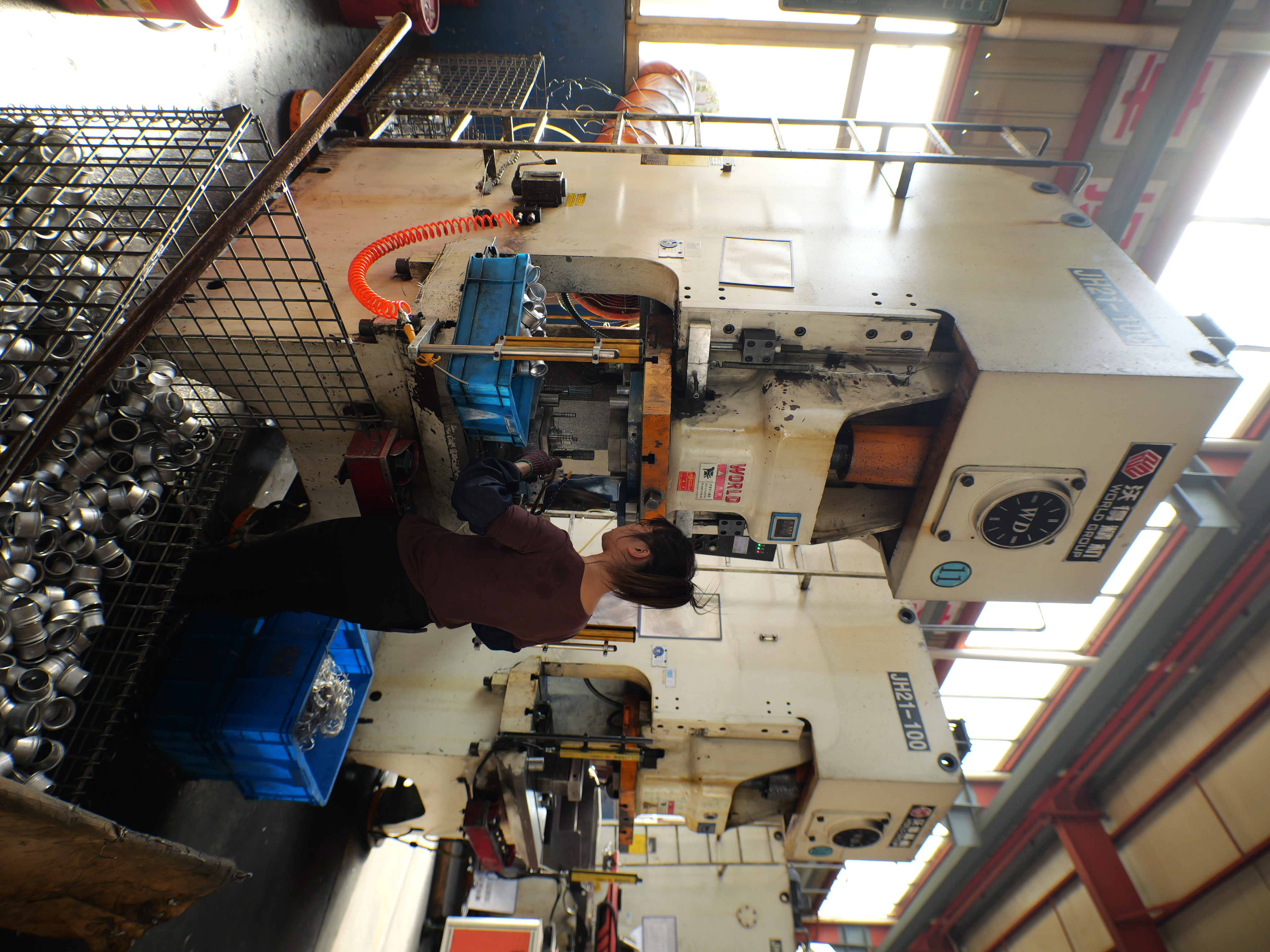
Step 6: Set Up the Press and Approve the First Article for Safe, Repeatable Stamping
Imagine investing time and resources into tooling, only to face costly rework or scrap due to a rushed setup. Setting up your metal stamping press machine correctly is the bridge between a validated process and consistent, high-quality output. Let’s walk through how to ensure a safe, stable launch—so every stamped part meets your expectations from the very first hit.
Die Set and Alignment Checklist
Sounds complex? It doesn’t have to be. A systematic approach using proven checklists and best practices can transform your press setup from a risky guess into a repeatable routine. Here’s an essential startup sequence, blending insights from industry experts and practical shop-floor experience:
- Verify Die ID and Documentation: Confirm that the correct die is staged, with the right part number and revision. Cross-check against the job traveler and setup instructions.
- Clean Clamp/Bolster and Die Seats: Remove all debris and old lube from the press table and die surfaces. A clean seat prevents uneven force and extends die life.
- Check Shut Height and Counterbalance: Set the press shut height to match die specs, then adjust the counterbalance for the die weight. This keeps the slide stable and prevents premature wear.
- Align Feed, Pilots, and Sensors: Position the strip or blank squarely in the die. Engage pilots and check all sensors for correct placement and function.
- Validate Feed Straightness and Timing: Run the feeder in inching mode to ensure smooth, straight movement—no jams or misfeeds.
- Sensor I/O and Lubrication Flow: Test all sensor inputs/outputs and confirm that lubrication is flowing to all required points. Adjust flow for material and operation.
- Scrap Evacuation: Clear scrap chutes and verify that slugs and offcuts have a clear path out of the die.
- Low-Speed Hand Cycling: Cycle the press slowly by hand, monitoring tonnage and checking for interference at each station.
Safety Checks for Industrial Stamping Machine Operation
Before powering up, pause and run through these critical safety checks. They’re the difference between a smooth launch and an incident:
- Personal Protective Equipment (PPE): Gloves, eye/face protection, hearing protection.
- Machine Guards: Ensure all guards, shields, and barriers are in place and functional.
- Emergency Stops (E-stops): Test every E-stop for proper operation.
- Light Curtains and Two-Hand Controls: Confirm that all safety interlocks and controls are active and working.
- Clear Work Zone: Verify that no tools, loose parts, or personnel are in the press area before cycling.
Never bypass sensor faults to meet rate; fix root cause before ramping up.
First Article and Run Approval
Once the steel stamping machine is set, it’s time for the moment of truth—the first article. Here’s how to make that first hit count:
- Capture Press Signature: Record the tonnage curve and press signature at the first good hit. This baseline helps spot drift or issues in future runs.
- Visual and Dimensional Inspection: Check part ejection, burr direction, and critical features. Use the drawing and measurement plan as your guide.
- Approve Against Specs: Only release production after the first article matches all requirements—dimensions, surface finish, and functional checks.
- Document Baseline Conditions: Record setup parameters, sensor settings, and inspection results for traceability.
By following this methodical setup and approval process, you’ll create a safe, repeatable workflow that protects both your people and your industrial stamping machine investment. The result? Fewer surprises, faster ramp-up, and a stable foundation for quality control. Next, we’ll dive into how to lock in quality with robust inspection and statistical process control (SPC).
Step 7: Control Quality with Inspection and SPC for Precision Metal Stamping
Ever wondered how manufacturers keep every stamped part within spec, even when producing thousands per hour? The answer lies in robust inspection and statistical process control (SPC) methods that lock in dimensional accuracy and prevent costly defects. Let’s explore how to build a quality stamping process that consistently delivers top-tier results—no matter the production volume.
Create the Measurement Plan and Datum Strategy
Imagine you’re tasked with inspecting a batch of precision metal stamping components. Where do you start? The foundation is a measurement plan rooted in Geometric Dimensioning and Tolerancing (GD&T). This plan defines which features are critical, how they relate to datums, and what tolerances must be met for fit and function. Always align your inspection to the datum scheme specified in the drawing—this ensures measurement results reflect real-world assembly, not just convenient reference points.
Measure to the datum scheme used in the drawing—do not re-datum the part to make results look better.
Choose Appropriate Inspection Methods
Not all features require the same inspection tools. For example, you might use a coordinate measuring machine (CMM) to check tight positional tolerances on holes, while a profile gauge quickly verifies flange shape. Here’s a practical mapping of feature types to common inspection methods in the stamping manufacturing process:
| Feature | Tool/Method | Sample Frequency | Acceptance Check |
|---|---|---|---|
| Mounting Holes | CMM or Vision System | 1 per shift or per lot | Positional Tolerance |
| Flanges | Profile Gauge | Every 10 parts | Profile/Flatness |
| Drawn Walls | Micrometer/Thickness Gauge | Every 20 parts | Wall Thickness |
| Burr Height | Go/No-Go Gauge | Every 10 parts | Burr ≤ Spec Limit |
| Cosmetic Surfaces | Visual/Tactile Inspection | Every 50 parts | Surface Finish/Defects |
For high-volume runs, consider automated vision systems or in-die sensors to monitor stamped parts in real time. This approach supports both quality stamping and process efficiency, especially for complex sheet metal stampings.
Establish Control Limits and Reaction Plans
Once your inspection plan is set, it’s time to lock in process stability with SPC. By collecting measurement data on key features—such as hole diameter or flange width—you can monitor trends and catch drift before it becomes a problem. Here’s how to react if things go off track:
- Tool clean/polish if burrs or edge defects increase
- Adjust lubricant flow if surface finish or part ejection suffers
- Tweak bead or shut height within authorized limits if dimensions trend out of spec
- Pause production and review process if control limits are breached
Don’t forget: before launching capability studies, always complete a gauge R&R (repeatability and reproducibility) assessment. This ensures your measurement system is accurate and reliable—a must for true precision stamping.
Sampling frequencies should be set based on risk and production volume. While some organizations follow detailed sampling plans per ISO or company quality systems, a general rule is to increase inspection frequency for critical or high-risk features.
By implementing these best practices, you’ll notice fewer defects, less scrap, and more consistent quality in your metal stamping components. This evidence-based approach to precision metal processing not only protects your bottom line, but also builds trust with customers who demand reliable, high-quality stamped parts every time. Next, we’ll dive into the business case and supplier selection—ensuring your stamping process is both competitive and sustainable.
Step 8: Benchmark Costs and Select Suppliers Wisely for Competitive Stamping Projects
When you’re planning a stamping manufacturing process, choosing the right supplier can make or break your project’s success. With so many metal stamping companies offering a range of capabilities, certifications, and pricing models, how do you make a decision that’s both cost-effective and low-risk? Let’s walk through a practical approach to modeling costs, crafting a robust RFP, and objectively comparing suppliers—so you can secure reliable custom metal stamping and long-term value.
Model Cost Drivers and Volume Breakpoints
Ever wondered why two quotes for the same part can be miles apart? It comes down to understanding all the elements that drive the total cost. Here’s a breakdown of key cost drivers you should model before sending out RFQs for metal pressing services or custom metal stamping services:
| Cost Element | Driver | Notes |
|---|---|---|
| Die Build | Complexity, material, tool life | High upfront, amortized over volume |
| Steels/Coatings | Material type, thickness, finish | Impacts both die and part cost |
| Tryout | Number of iterations, risk features | CAE can reduce cycles and cost |
| Spare Inserts | Wear-prone features, run length | Plan for maintenance and downtime |
| Setup Time | Die complexity, press changeover | Longer setups increase cost per run |
| Run Rate | Press speed, automation | Faster rates lower per-part cost |
| Scrap | Material yield, process stability | Optimized layouts reduce waste |
| Packaging | Part protection, logistics | Custom trays vs. bulk can affect cost |
| Freight | Supplier location, shipment mode | Local suppliers can cut lead time and cost |
Remember, the more parts you produce, the lower your per-part tooling cost. High-volume automotive stamping projects often justify higher initial investments in robust dies, while short runs may benefit from flexible tooling and lower upfront costs.
Issue a Detailed RFP and Evaluate Quotes
How do you separate a top-tier metal stamping company from the rest? A well-prepared RFP (Request for Proposal) is your first line of defense. Here’s a checklist of smart questions and requirements to include:
- What’s your rationale for die type selection?
- Describe your CAE/simulation workflow and how it reduces tryout risk.
- What’s the expected die life and maintenance plan?
- How do you manage change requests during production?
- What are your standard lead times and capacity for urgent orders?
- Can you provide sample timing and a gauge plan?
- List spare parts included and ongoing support/training options.
- Detail your quality certifications (ISO 9001, IATF 16949, etc.).
- How do you track material certification and sustainability compliance?
These questions will help you gauge not just price, but also the supplier’s ability to deliver reliable custom metal stamping at scale—especially for demanding automotive stamping or high-precision applications.
Compare Supplier Capabilities, Timing, and Risk Controls
It’s tempting to go with the lowest quote, but capabilities and track record matter just as much as cost. Here’s a sample comparison table to help you evaluate leading metal stamping manufacturers, including a concrete example of a supplier that leverages CAE and IATF-backed quality:
| Supplier | Core Strengths | Certifications | Simulation/DFM Support | Lead Time | Risk Controls | Limitations |
|---|---|---|---|---|---|---|
| Shaoyi Metal Technology | CAE-driven die design; IATF 16949; deep engineering collaboration; rapid prototyping to mass production | IATF 16949 | Advanced CAE, structural reviews, formability analysis | Short (rapid prototyping); scalable to high volume | Simulation-led risk mitigation, robust quality tracking | Focused on automotive and high-precision sectors |
| Acro Metal Stamping Co. | Complex, tight-tolerance parts; strong engineering | ISO 9001 | Engineering support, some simulation | Medium | SPC, vision inspection | Less focus on ultra-high volume |
| American Industrial Company (AIC) | Automotive focus; automated assembly | IATF 16949 | APQP, PPAP, some simulation | Short–medium | Automated QC, high capacity | Primarily high-volume |
| HPL Stampings, Inc. | Short-run, prototypes; fast turnaround | ISO 9001 | Quick DFM, limited simulation | Very short | Rapid tooling, flexible volumes | Not for high-volume runs |
When benchmarking, prioritize suppliers who demonstrate deep process knowledge, robust quality systems, and proven CAE/simulation workflows—these factors reduce risk and speed up your time to market. For automotive stamping, IATF 16949 certification is often a must-have, while for custom metal stamping services in other industries, ISO 9001 or sector-specific credentials may suffice.
Negotiate Support, Tryout, and PPAP Scope
Once you’ve shortlisted your top metal stamping manufacturers, dig into the details that impact long-term project success:
- Clarify how tryout costs, sample runs, and PPAP (Production Part Approval Process) are handled.
- Negotiate clear support terms—such as spare insert supply, preventive maintenance, and rapid response to quality issues.
- Define escalation paths for engineering changes or supply chain disruptions.
By following these steps, you’ll not only secure the best possible pricing, but also build a resilient partnership with your chosen metal stamping company—one that supports your goals from prototype to mass production.
With costs benchmarked and partners selected, you’re ready to maintain and optimize your stamping operation for the long haul. Next, we’ll explore how to troubleshoot, sustain, and improve your process for lasting success.

Step 9: Troubleshoot, Maintain, and Optimize for Sustainable Stamping Operations
Ever had your stamping line grind to a halt because of a recurring defect, or watched scrap bins fill up faster than finished parts? Sustaining a reliable stamping manufacturing process isn’t just about running presses—it’s about solving problems fast, preventing downtime, and making the most of every coil. Let’s break down how you can troubleshoot defects, maintain your dies, and boost sustainability for long-term success in steel stamping and beyond.
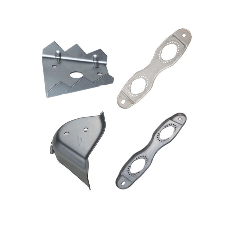
Troubleshoot Common Stamping Defects
Imagine you’re inspecting a batch of stamped steel parts and spot cracks, wrinkles, or burrs. What’s your next move? Effective troubleshooting starts with understanding both symptoms and root causes. Here’s a practical table to guide your response to typical stamping metal process issues, including those encountered in blank stamping, coining stamping, and other operations:
| Symptom | Likely Causes | Immediate Checks | Corrective Actions |
|---|---|---|---|
| Splits/Cracks | Material brittleness, excessive strain, worn die, high pressure | Check material specs, inspect die edges, review press settings | Switch to tougher material, polish die, adjust pressure/speed |
| Wrinkles | Uneven strain, loose blank holding, low binder force | Inspect binder, check blank position, review die geometry | Increase binder force, optimize die design, improve blank holding |
| Burrs/Blanking Burrs | Dull punch/die, improper clearance, worn tooling | Examine cutting edges, measure clearance, check for wear | Sharpen tools, reset clearances, replace worn inserts |
| Dimensional Drift | Tool wear, loose fasteners, thermal expansion | Check die alignment, torque on fasteners, part measurements | Regrind/replace inserts, retighten hardware, adjust die set |
| Galling | Insufficient lubrication, incompatible materials, rough die surface | Review lube system, inspect die finish, check material pairing | Increase lubrication, polish die, use extreme pressure (EP) grease |
| Slug Pull/Coil Set | Improper scrap removal, weak slug retention, coil memory | Observe scrap flow, check slug retention, review coil handling | Improve scrap chutes, enhance slug retention, pre-flatten coil |
Maintain sharp, consistent clearances—dull tooling multiplies burr height and downstream problems.
Plan Preventive Maintenance and Spares
When you’re running high-volume stamping, waiting for a failure isn’t an option. Preventive maintenance is your best defense against costly downtime and quality escapes. Here’s a maintenance schedule you can tailor to your operation:
- Per Shift: Clean dies, check sensors, inspect lube flow, remove scrap buildup
- Weekly: Deburr cutting edges, validate fastener torque, check for insert wear
- Monthly: Deep clean dies, inspect and rotate inserts, review sensor calibration, inspect lube system and apply extreme pressure (EP) grease as needed
Keep detailed records of all maintenance actions and defects. Use a work order system to track repairs, prioritize urgent work, and identify recurring issues. This data-driven approach improves both uptime and quality over time.
Reduce Scrap and Improve Sustainability
Ever wondered how much profit is lost to scrap? Optimizing material yield is one of the fastest ways to boost sustainability in stamping operations. Here’s how you can make an immediate impact:
- Analyze defect Pareto charts and correlate with coil lots, lubrication type, and press signatures to pinpoint root causes
- Revisit strip layouts—nesting left/right or multiple parts can reduce scrap in blank stamping and coining stamping setups
- Add geometric stiffeners or redesign features to allow thinner material without sacrificing strength
- Recycle offcuts and implement return-to-mill programs where possible
- Regrind or replace inserts before dimensional drift impacts capability
By emphasizing prevention, rapid troubleshooting, and smart material use, you’ll create a stamping metal process that’s both resilient and efficient. This approach keeps your operation competitive, sustainable, and ready for whatever comes next in the world of stamped steel parts.
Frequently Asked Questions About the Stamping Manufacturing Process
1. What are the main steps involved in the stamping manufacturing process?
The stamping manufacturing process typically includes defining project requirements, selecting materials and gauge, planning the process and press, engineering die design, validating with simulation and tryout, setting up the press, controlling quality with inspection and SPC, benchmarking costs and suppliers, and maintaining and optimizing sustainability. Each step ensures precision, quality, and cost efficiency in producing stamped metal parts.
2. How does automation impact the stamping process in manufacturing?
Automation in stamping integrates robotic arms, automatic transfer systems, and quality inspection equipment to streamline production. This reduces manual intervention, increases consistency, and allows for higher production speeds. Automated systems also enhance safety and support real-time monitoring, which is crucial for maintaining quality and minimizing downtime.
3. What factors influence material selection in metal stamping?
Material selection depends on the part’s function, required strength, formability, corrosion resistance, and cost. Common choices include low-carbon steel, HSLA, stainless steel, and aluminum alloys, each offering specific benefits for different applications. Considerations like springback, drawability, and coating compatibility are also essential for optimal results.
4. How is quality ensured in the stamping manufacturing process?
Quality is maintained through robust inspection plans, adherence to GD&T standards, and the use of statistical process control (SPC). Regular measurement of critical features, in-process monitoring, and clear reaction plans for deviations help prevent defects and maintain consistent output. Advanced suppliers may also use CAE simulations to predict and address potential quality issues before production.
5. What should be considered when choosing a metal stamping supplier?
Key factors include the supplier’s technical capabilities, quality certifications (such as IATF 16949 or ISO 9001), simulation and engineering support, lead times, risk controls, and experience with similar projects. It’s also important to review their maintenance plans, ability to handle change requests, and overall track record in delivering reliable, cost-effective stamped parts.