 Small batches, high standards. Our rapid prototyping service makes validation faster and easier —

Automotive Stamping Dies: Smarter Tryout, Fewer Defects, Longer Life
Essential foundations of automotive stamping dies
Ever wondered how a flat sheet of steel becomes a perfectly contoured car door or a precisely formed chassis rail? The answer lies in the world of automotive stamping dies—specialized tools that shape, cut, and refine sheet metal into the critical components that define vehicle safety, appearance, and performance. Understanding these dies, their terminology, and their process flow is the first step to reducing ambiguity and making smarter decisions across design, purchasing, and manufacturing teams.
What is a die in manufacturing for automotive applications?
At its core, what is a die in manufacturing? In automotive production, a stamping die is a hardened tool used to cut or form sheet metal under high pressure. These dies are meticulously engineered to deliver precise shapes, dimensions, and surface finishes, directly impacting everything from body-in-white panels to safety-critical brackets. The term "die" encompasses a broad family of tooling, each purpose-built for different operations, but all share a common goal: transforming flat metal into functional, accurate parts at scale.
- Blank: The initial flat sheet or pre-cut metal shape loaded into the die.
- Binder: A die component that holds and controls the flow of sheet metal during forming.
- Die set: The complete assembly of upper and lower die halves, precisely aligned to form or cut the part.
- Punch: The male tool that presses into or through the sheet metal to shape or cut features.
- Stripper: Removes the finished part or scrap from the punch after forming or cutting.
- Springback: The elastic recovery of metal after forming, which can affect final dimensions.
How the stamping process transforms sheet metal into precision parts
Sounds complex? Let’s break it down. The sheet metal stamping process is a sequence of operations, each performed by a specific die or die station:
- Blanking: Cutting the raw sheet into the basic outline of the part.
- Drawing: Forming the blank into a three-dimensional shape, such as a door panel or wheel housing.
- Flanging: Bending up the edges to add strength or provide mounting surfaces.
- Piercing: Creating holes or slots for fasteners, wiring, or assembly features.
- Trimming: Removing excess material for a clean, accurate final shape.
These steps often chain together in a process layout, moving the part from one die to the next, or through a multi-station die, depending on complexity and production volume.
[Process Flow: Blanking → Drawing → Flanging → Piercing → Trimming → Inspection]
From design to production
Tooling choices—such as die material, geometry, and surface finish—directly influence dimensional accuracy, surface quality, and production throughput. But the die’s impact starts even earlier. Upstream decisions like material grade and lubrication plan affect how the metal flows, how much force is required, and how long the die lasts. Downstream, requirements such as inspection criteria and packaging methods ensure that stamped parts meet quality targets and arrive intact at the next assembly stage.
Upstream material and lubrication decisions often determine downstream die performance; align them early.
For example, selecting a high-strength steel sheet for a side impact beam demands a robust die design and careful control of springback. Conversely, a simple aluminum bracket may allow for faster cycling and less complex tooling. In either case, clear terminology and early cross-functional alignment prevent costly rework and ensure that every stakeholder—from design to purchasing to production—speaks the same language.
In summary, mastering the essential foundations of automotive stamping dies—terminology, process flow, and lifecycle context—empowers teams to make informed decisions that drive quality, efficiency, and cost control across the entire automotive value chain. As you explore deeper topics, keep these basics in mind—they are the building blocks for every successful stamping project.
Die types and when to use them
When you’re staring down a new stamping project, the question isn’t just “what die do I need?”—it’s “which die type will deliver the best quality, efficiency, and cost for my part’s needs?” The world of automotive stamping dies offers a diverse toolkit, but choosing the right one can make or break your program’s success. Let’s demystify the main types of stamping dies and give you a decision framework you can use for smarter, faster tooling selection.
Types of stamping dies and typical use cases
Imagine you’re building a car door, a seat bracket, or a complex reinforcement panel. Each part’s geometry, tolerance, and production volume will steer you toward a specific die family. Here’s what you’ll encounter on the shop floor:
| Die Type | Best For | Operation Count | Surface Class | Volume Suitability | Changeover Complexity | Maintenance Needs |
|---|---|---|---|---|---|---|
| Progressive Die | Small/medium parts with multiple features | Many (sequential stations) | Medium to High | High-volume | Low (coil-fed, minimal manual intervention) | High (many working elements require regular checks) |
| Compound Die | Simple, flat parts (washers, gaskets) | Few (multiple ops in one stroke) | Medium | Low to medium volume | Medium (single hit, but part-specific) | Low to Medium (simpler structure) |
| Transfer Die | Large, deep, or complex parts | Many (separate stations, part transferred) | High | Medium to high volume | High (setup and transfer system) | High (die and transfer mechanism) |
| Single-Hit Die | Prototypes, basic shapes, low volume | One | Low to Medium | Prototype/short runs | Low | Low |
| Draw Die | Deep-formed panels (oil pans, door outers) | One (drawing operation) | High | Medium to high volume | Medium | Medium to High (depends on draw depth) |
| Trim Die | Final shape, edge finishing | One (trimming) | High | Any | Low | Low |
Progressive versus compound: What really changes on the shop floor?
Let’s get practical. Progressive die metal stamping is the backbone of high-volume production—think brackets, clips, or small body reinforcements. Here, a coil of sheet metal feeds through a series of stations, each performing a different operation (blanking, piercing, forming, etc.) with every press stroke. The primary advantage of a progressive press is its ability to combine speed, consistency, and low labor input. If you need thousands or millions of parts with repeatable quality, progressive dies are your go-to.
By contrast, compound die stamping handles simpler, flat parts—often in smaller batches. All required actions (like punching and blanking) happen in a single press stroke. This makes compound dies cost-effective for lower volumes and quick changeovers, but they lack the automation and throughput of progressive dies. You’ll notice they’re less suited for intricate or multi-featured parts.
When a dedicated draw die is the right choice
Complex shapes—like deep oil pans or exterior panels—demand a different approach. Transfer dies and dedicated draw dies shine here, as they can handle large blanks, deep draws, and multiple forming steps. In transfer die stamping, mechanical arms move each part between stations, allowing for more flexibility and the ability to form, pierce, and trim in sequence. However, this flexibility comes with higher setup and maintenance overhead, and careful attention to transfer window constraints is required.
- Progressive dies: Best for high-volume, high-speed runs of smaller, multi-featured parts.
- Compound dies: Suited for simple, flat parts where precision is key and run size is moderate.
- Transfer/draw dies: Handle large, deep, or complex shapes, especially when multiple forming steps are required.
Common pitfalls in die selection
- Ignoring transfer window or press bed constraints for large parts
- Underestimating scrap management in progressive layouts
- Choosing a complex die type for low-volume/prototype runs
- Overlooking maintenance needs for intricate stamping tooling
The right die type balances part complexity, volume, and cost—choose fit-for-purpose tooling to avoid costly redesigns and downtime.
In summary, understanding the types of dies available—progressive, compound, transfer, draw, trim, and single-hit—empowers you to match your sheet metal stamping dies to the unique demands of each project. As you move forward, keep in mind that the next challenge is not just selecting the die, but ensuring it’s engineered to handle the specific material and forming strategy your part requires.
Forming modern materials without surprises
Ever tried to form a complex car panel and ended up with unexpected wrinkles or a part that just won’t fit the gauge? When working with today’s advanced materials, it’s not just about picking a die—it’s about understanding how steel sheet stamping and aluminum forming each come with unique challenges and require tailored strategies. Let’s break down what you need to know to get predictable results from your automotive stamping dies.
AHSS and UHSS forming considerations that designers must respect
Automotive manufacturers are increasingly turning to Advanced High Strength Steel (AHSS) and Ultra High Strength Steel (UHSS) to reduce vehicle weight while maintaining safety. But these steels present new hurdles for metal forming dies—especially in controlling metal flow, managing springback, and selecting the right lubrication plan.
- Higher work hardening rates: AHSS and UHSS quickly become stronger as they are deformed, which means more force is needed and the risk of cracking rises if the die geometry isn’t right.
- Springback risk: After forming, these steels tend to "spring back"—returning slightly toward their original shape—which can throw off your part’s final dimensions. Robust compensation strategies, such as over-forming or using stake beads, are essential to minimize this effect [AHSS Insights].
- Lubrication demands: The localized pressures and temperatures in forming AHSS/UHSS require advanced synthetic lubricants that provide uniform coverage, better cooling, and minimal residue, supporting both die life and downstream weldability.
- Binder and bead design: Draw bead geometry, binder force tuning, and addendum optimization must be dialed in to control flow and avoid splits or wrinkles.
For example, using retractable or hybrid stake beads can apply targeted post-stretch to sidewalls, reducing angular change and sidewall curl—two common forms of springback. Modern presses with multipoint binder force control allow you to fine-tune pressure during the stroke, further improving dimensional accuracy.
Dialing in lubrication and bead geometry for steel sheet stamping
Why do some stamped steel sheet parts come out flawless while others suffer from surface scuffing or edge cracks? Often, it comes down to the synergy between lubrication, bead design, and process control. For sheet metal for stamping, the right lubricant reduces friction and die wear, while the bead geometry manages how the metal flows during the draw.
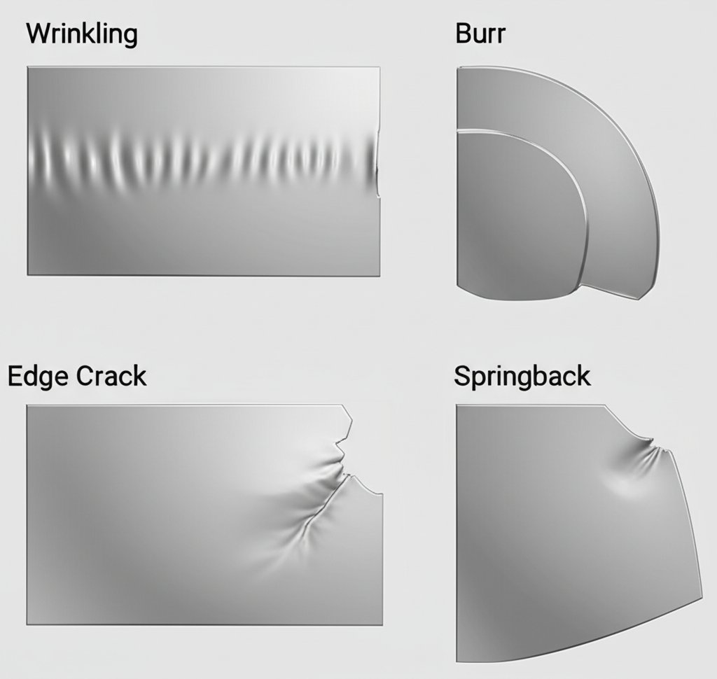
- Wrinkling: Countered by increasing binder force or optimizing bead placement.
- Edge cracking: Controlled by reducing draw severity, adjusting radii, or using tailored blanks.
- Surface scuffing: Mitigated through advanced lubricants and smoother die finishes.
- Springback: Minimized with post-stretch operations, over-forming, or design features like stiffening darts and vertical beads.
Imagine tuning the stake bead height or using a hybrid bead design to achieve just enough post-stretch—this not only helps eliminate curl but also makes your process less sensitive to material variations. The result? Fewer surprises and more parts that meet spec on the first try.
Aluminum panel stamping: Avoiding galling and orange peel
Switching gears to aluminum, you’ll notice different challenges. Aluminum alloys offer high strength-to-weight ratios and natural corrosion resistance, but they are softer and more prone to surface defects during aluminum stamping dies operations.
- Galling: Aluminum tends to stick to tool surfaces, causing scratches and rapid die wear. Counter this by using specialized die coatings (like nitrides or DLC) and lubricants formulated for aluminum.
- Surface damage/orange peel: Careful control of die finish and lubricant choice is key. Thermal management is also important, as frictional heat can exacerbate galling and surface defects.
- Formability: Aluminum is less ductile than steel, so tighter radii or deep draws may require annealing or multi-stage forming to avoid splits.
It’s also important to consider potential bimetallic corrosion if aluminum parts are mated with steel fasteners or components—anodizing or painting can help mitigate this risk.
-
Key material-specific risks and countermeasures:
- Wrinkling → Binder force tuning, addendum optimization
- Edge cracking → Tailored blanks, optimized radii
- Surface scuffing/galling → Advanced lubricants, die coatings
- Springback → Stake beads, over-forming, post-stretch, stiffening features
Robust draw development reduces tryout churn more than any single late-stage die tweak.
To sum up, mastering the interplay of material properties, die design, lubrication, and process control is the secret to success when forming modern steels and aluminum. By anticipating risks and building in effective countermeasures, you’ll spend less time troubleshooting and more time producing quality parts. Next, we’ll explore how to translate these material and process insights into a practical die design and specification blueprint—ensuring your investment in automotive stamping dies pays off across the entire part lifecycle.
Die design and specification blueprint
When you’re tasked with specifying a stamping die design for automotive applications, the challenge is more than just “drawing a tool.” You’re defining the DNA of quality, cost, and service life for every part that die will produce. So, how do you create a specification that’s clear, robust, and easily understood by both engineering and procurement? Let’s walk through a practical, reusable blueprint for metal stamping die design—one that reduces ambiguity and streamlines supplier handoffs.
Stamping die design essentials: Steel selection, heat treatment, and surface protection
Imagine you’re building a die for a high-volume body panel. Your choices—base material, tool steel, and surface treatments—directly impact not just performance, but also long-term maintenance and part consistency. Here’s how to break it down:
- Die base material: Standard die sets often use cast iron (G2500/NAAMS or equivalent) with minimum wall thicknesses—1.25" for outside and 1.0" for inside walls—to ensure structural strength and longevity.
-
Tool steel selection: For cutting and forming sections, commonly used grades include:
- D2: High-carbon, high-chromium; excellent wear resistance for long-run blanking, punching, and forming dies.
- A2: Air-hardening; balances toughness and wear resistance, ideal for blanking/forming punches and die trimming.
- S7: Shock-resistant; used for applications needing high impact resistance, like punches and rivet sets.
- H13: Hot-work; maintains hardness at high temperatures, suitable for aluminum die casting or hot forming.
- Heat treatment objectives: The goal is to achieve a balance—high surface hardness for wear, with enough core toughness to resist chipping. For example, D2 can reach 62–64 HRC after hardening and tempering, while H13 is typically treated to HRC 46–52 to balance hardness and high-temperature toughness. Always stamp the tool steel type on each section for traceability.
-
Surface coatings: Options include nitriding, TiN, TiCN, AlCrN, and DLC. Select coatings based on:
- Material type: Aluminum often requires DLC or nitrided surfaces to combat galling; AHSS may benefit from TiCN for extra wear protection.
- Lubrication plan: Some coatings work better with specific lubricants or dry conditions—coordinate with your process engineer.
When coatings pay off—and when they do not
Not every manufacturing die needs a high-end coating. For high-wear areas or when stamping abrasive materials, hard coatings can extend tool life and reduce downtime. But if your part is low-volume or the wear risk is minimal, a standard die finish may suffice. The key is to match the coating to the expected wear mode and lubrication environment.
GD&T for Class A versus Class B tools
How tight do your tolerances need to be? This is where geometric dimensioning and tolerancing (GD&T) comes in. For Class A (exterior) surfaces—think visible body panels—specify tighter profile, flatness, and controlled radii, plus robust datum strategies for repeatable location. For Class B (structural or hidden parts), functional tolerances and economical finishing are typically enough. Align your sheet metal stamping design with international standards like ISO 2768 for general tolerances and ISO 1101 or ASME Y14.5 for GD&T.
-
Specification checklist for stamping die components:
- Die base material: ____________________
- Tool steel grade (cutting/forming): ____________________
- Heat treatment goal (HRC, core vs. surface): ____________________
- Surface coating (if any): ____________________
- Lubrication plan: ____________________
- Sensor/protection strategy: ____________________
- GD&T/inspection datums: ____________________
- Class A/B finish requirements: ____________________
- OEM/industry standards referenced: ____________________
Always align your metal stamping design and specification language with OEM standards (ISO, SAE, ASTM) to ensure clarity and prevent costly misunderstandings.
By using a structured checklist and referencing the right standards, you’ll ensure your sheet metal stamping design is both manufacturable and robust—minimizing RFQ ambiguities and smoothing supplier collaboration. Next, we’ll look at how to translate these specs into actionable process planning to reduce risk and drive consistent, high-quality production.
Process planning methods that reduce risk in the metal stamping process
Ever wondered why some stamping lines run smoothly from day one, while others struggle with costly rework and missed deadlines? The answer often lies in the early planning stages of the metal stamping process. Let’s walk through a practical, step-by-step approach to process planning that helps you reduce risk, control costs, and consistently hit your throughput targets—no matter how complex your automotive stamping dies might be.
Estimating tonnage and energy without over or under sizing
Imagine you’re about to launch a new part. The first question is: does your press have the muscle to handle it? Estimating press tonnage is a foundational step in the stamping process in manufacturing. The required force depends on the part’s shear perimeter, material thickness, and the material’s shear strength. Here’s the basic logic:
- Shear perimeter: Add up the total length of all cuts in your blank or pierced features.
- Material thickness: Thicker materials require more force—doubling thickness nearly doubles the tonnage needed.
- Material strength: Harder materials (like stainless steel) need more tonnage than softer ones (like aluminum).
The formula for punching force is: Punching force = Shear Perimeter × Thickness × Material Shear Strength. To convert this force to tons, divide by 9,810 (since 1 ton ≈ 9,810 N), and always add a safety factor (typically 1.2–1.3) to ensure reliability. Too little tonnage results in incomplete cuts and die damage; too much leads to unnecessary equipment costs and accelerated die wear. That’s why balancing press capacity is crucial for a robust metal pressing process.
Blank holder force strategy for robust draw control
If your part involves drawing—like forming a deep door panel—blank holder force becomes your next focus. The blank holder (or binder) controls metal flow, preventing wrinkles or splits. Here’s what drives your force strategy:
- Binder area: Larger contact areas typically require higher forces to hold the material steady without tearing.
- Bead resistance: Draw beads add targeted resistance, helping control how and where the metal stretches.
- Draw depth: Deeper draws require careful balancing—too much force causes splits, too little leads to wrinkling.
Fine-tuning binder force and bead geometry is often an iterative process, validated through simulation and tryout. Modern presses with multipoint binder control allow you to adjust force dynamically, improving consistency across part runs and materials.
Die clearance and edge quality methodology
Ever noticed burrs or rapid die wear after a few runs? Die clearance—the gap between the punch and die—directly impacts edge quality and tool longevity. Too little clearance means higher punching force and faster wear; too much can cause excessive burrs and poor part edges. As a rule of thumb, target die clearance at 5–10% of material thickness, but always validate with your material and part geometry in mind.
Cycle time drivers—like part complexity, automation, and transfer speed—should also be mapped early. This ensures your sheet metal stamping process is balanced for both efficiency and quality.
Sequenced planning steps for the manufacturing stamping process
- Gather material data: Collect material certs, thickness, and mechanical properties.
- Develop blank layout: Calculate shear perimeter and optimize nesting to reduce scrap.
- Estimate press tonnage: Use formulas and safety factors to determine minimum press size.
- Specify die clearance: Set punch-to-die gap based on material thickness and type.
- Determine blank holder and bead strategy: Design binder area and select bead geometry for controlled metal flow.
- Check press capability: Compare your requirements with press manufacturer curves for force and energy.
- Plan for in-die sensors: Integrate sensors for part presence, stripper position, and overload detection to protect tooling and minimize downtime.
- Balance the line: Sequence dies and automation to avoid bottlenecks and maximize throughput.
-
Key data sources to consult:
- Material certifications
- Press manufacturer capability curves
- Tooling supplier handbooks
Accurate planning and early validation in the manufacturing stamping process are the best insurance against costly rework and missed deadlines.
So, how does stamping work? In essence, it’s about bringing together the right material, die, and press—supported by precise planning and data-driven decisions. By following a structured process, you’ll reduce surprises, improve quality, and set your sheet metal stamping process up for repeatable success. Next, we’ll dive into tryout and validation—turning your plan into real-world results on the shop floor.
Tryout validation and quality control checkpoints for precision die stamping
When you finally move from process planning to real-world production, the question shifts from "Will it work?" to "How do we prove it, repeat it, and avoid surprises?" The answer: a structured, stepwise approach to die tryout and quality control. In high-stakes automotive environments, every sheet metal stamping press run must meet exacting standards—making validation and inspection as critical as the tooling itself. Here’s how to ensure your precision die stamping delivers reliable results, every time.
First-off tryout sequence and acceptance readiness
Imagine you’re launching a new die. It’s tempting to rush the first parts through, but skipping steps can lead to costly rework. Here’s a proven sequence to follow for production metal stamping:
- Soft-tool or simulation correlation: Before cutting steel, validate the process with soft tooling or digital simulation. This step helps catch major forming or fit issues early, reducing downstream surprises [The Fabricator].
- Steel tryout: Produce the first-off parts with the actual die set in the sheet metal stamping press. Assess part shape, surface quality, and die function under realistic conditions.
- Process tuning: Adjust binder force, bead geometry, and press settings. Fine-tune until parts consistently meet dimensional and cosmetic targets.
- PPAP-style documentation: Record all process parameters, material lots, and inspection results. This creates a baseline for future production and supports customer approval.
Lock the datum scheme before tuning the process or capability data will be misleading.
Dimensional validation strategy for stamped sheet metal
How do you know your stamped steel parts really meet spec? Relying on visual checks alone isn’t enough. Instead, use a layered inspection approach:
- Blanks: Inspect blank size and geometry before forming to ensure proper material flow.
- Formed radii: Measure critical bends and curves for consistency and to catch thinning or over-stretching early.
- Pierce location: Use go/no-go gauges or optical systems to verify hole and slot positions.
- Flange angles: Check flange orientation and angle to prevent assembly issues downstream.
- Trimmed edges: Inspect for burrs, clean cuts, and edge quality—key for both safety and fit.
For high-precision or safety-critical stamped sheet metal parts, advanced measurement tools come into play:
- Coordinate Measuring Machine (CMM): Captures 3D dimensions for complex features and tight tolerances.
- Laser scanning: Quickly compares part geometry to CAD models, ideal for rapid feedback during ramp-up.
- Go/no-go gauges: Provide fast, repeatable checks for critical features right on the shop floor.
From run at rate to steady state quality control
Quality isn’t just a one-time check—it’s a continuous process. Here’s how to manage inspection frequency and maintain process capability as you scale up:
- Ramp-up phase: Increase inspection frequency (every part or every few parts) to catch early process drift and validate adjustments.
- Steady-state production: Once capability is proven, shift to a sampling plan (e.g., every 10th or 50th part), based on process stability and customer requirements.
- Ongoing monitoring: Use Statistical Process Control (SPC) charts to track key dimensions and react quickly to trends or out-of-control conditions.
- Audit checks: Periodically perform full dimensional layouts and functional tests to confirm long-term die and process health.
-
Documentation artifacts to archive:
- Draw-development records
- Tryout and process tuning logs
- Deviation permits and corrective action reports
- Capability summaries (CP, CPK, PPAP records)
In summary, a disciplined approach to tryout validation and quality control—supported by robust documentation and the right measurement technology—ensures your sheet metal stamping press produces parts that meet spec, every time. This not only protects your investment in production metal stamping but also builds confidence for downstream assembly and customers alike. Next, we’ll tackle troubleshooting: what to do when defects threaten to derail your launch or production run.
Troubleshooting defects before scrap escalates
Ever launched a new part, only to find wrinkles, splits, or a mysterious line marring the surface? Defects are a reality in the stamping metal process—but with the right playbook, you can link what you see to what needs fixing, fast. Let’s walk through the most common issues in steel stamping dies and how you can systematically diagnose and resolve them—before scrap piles up and costs spiral.
Systematic troubleshooting from symptom to stable fix
Imagine you’re inspecting a batch of panels and spot edge cracks, burrs, or the notorious shock line stamping defect. Where do you start? Effective troubleshooting begins with observation, root-cause analysis, and targeted corrective actions. Here’s a compact guide to the most frequent defects, their likely causes, and proven solutions:
| Defect | Common Causes | High-Leverage Corrective Actions |
|---|---|---|
| Wrinkling |
|
|
| Edge Cracks / Splits |
|
|
| Excessive Thinning |
|
|
| Burrs |
|
|
| Galling |
|
|
| Springback |
|
|
| Shock Line |
|
|
Change one variable at a time and log outcomes to avoid confounding.
Reducing burrs and improving edge integrity
Burrs and poor edge quality can quickly escalate into downstream assembly or safety issues. The root often lies in die clearance, tool wear, or misalignment. For example, if you notice burrs growing over a production run, check for worn edges on your steel stamping dies and verify punch-to-die alignment. Adjusting clearance is a quick fix, but lasting improvement may require regrinding or even redesigning the cutting section.
-
Pros:
- Quick clearance adjustment can reduce burrs immediately
- Regrinding extends tool life
-
Cons:
- Frequent regrinding reduces tool life over time
- Incorrect clearance adjustment can worsen other defects
When reviewing die design, consider the purpose of bypass notches in stamping dies: these notches help control the flow of material and prevent excessive stress in critical areas, reducing the likelihood of burrs and edge cracking during stamping and die cutting operations.
Controlling springback without chasing shims
Springback—where the part relaxes after forming—can be especially troublesome with high-strength steels. Don’t just chase the problem with shims or manual tweaks. Instead, address the root by increasing post-stretch (using stake beads or over-forming), refining die angles, or adjusting material selection. Simulation tools can help predict and compensate for springback before you cut steel, saving time and cost down the line.
-
Pros:
- Permanent die modifications yield more stable results
- Simulation reduces trial-and-error cycles
-
Cons:
- Die rework can be costly and time-consuming
- Material changes may require process requalification
Diagnosing and preventing the shock line stamping defect
The shock line stamping defect—a visible line on outer panels, often at door thresholds—can be a persistent cosmetic issue. It’s typically caused by tight radii, steep sidewall angles, or uncontrolled material flow in the die. As demonstrated in recent case studies, using CAE simulation to analyze unbending strain and contact pressure can accurately predict the location and severity of shock lines, guiding you to increase radii or adjust bead design for a cleaner result. This approach prevents costly rework and shortens the tryout cycle.
In summary, a disciplined, data-driven approach to troubleshooting—combined with a clear understanding of die geometry, material flow, and the purpose of bypass notches in stamping dies—empowers teams to solve stamping defects quickly and prevent scrap escalation. Next, we’ll explore how proactive maintenance planning can further extend die life and avoid unplanned downtime.
Maintenance planning and service life management
Ever wondered why some stamping dies seem to run for years with minimal fuss, while others are constantly sidelined for repairs? The secret isn’t just in the design—it’s in disciplined, proactive maintenance. Let’s break down how a smart maintenance strategy, tailored to the realities of die machining and die processing, keeps your stamping die machine producing top-quality parts and avoids costly unplanned downtime.
Planned maintenance intervals that match your production rhythm
Imagine your die as the heart of your stamping operation. Just like any high-performance machine, it needs regular care to deliver consistent results. Here’s how to structure maintenance routines so nothing slips through the cracks:
- Per shift: Quick clean-down to remove debris, visual check for obvious damage, and basic lubrication as needed.
- Per week: Deeper cleaning, edge inspection for wear or chipping, check for loose fasteners, and verify sensor function.
- Per production run: Inspect and deburr cutting and forming edges, check alignment, and monitor for abnormal noise or increased press tonnage (a sign of dulling or misalignment).
- Pre-storage: Full inspection, re-sharpening or edge reconditioning if needed, apply protective coatings, and document die condition for future reference.
By sticking to these intervals, you’ll catch issues early—before they escalate into expensive repairs or unplanned downtime. And if you’re running multiple stamping die machines, standardized checklists help ensure consistency across your operation.
Diagnosing wear modes before failure
Not all die wear looks the same. Identifying the specific wear mode is key to choosing the right fix and extending tool life. Let’s look at the most common types:
| Wear Mode | Telltale Signs | Recommended Intervention |
|---|---|---|
| Abrasive wear | Dull edges, gradual loss of sharpness, fine scratches along working surfaces | Re-sharpen cutting edges, increase lubrication, consider harder tool steel |
| Adhesion & galling | Metal transfer or build-up on die, scored or torn part surfaces, increased press force | Polish die surface, apply or refresh coatings, switch to a lubricant better suited for the material |
| Chipping | Small pieces missing from cutting edges, sudden burrs or out-of-tolerance parts | Edge reconditioning, check for misalignment, review press setup and die handling |
Routine inspection—both visual and using magnification for critical features—helps you spot these signs early. Advanced shops may also use non-destructive testing (NDT), like ultrasonic or X-ray, to detect subsurface cracks before they become catastrophic.
Capture die condition at pull and at install to tighten your root-cause loop.
Refurbish versus replace: Making the call in dies manufacturing
So, you’ve found damage—now what? Deciding whether to refurbish or replace a die component depends on:
- Damage localization: Is the wear or breakage limited to a replaceable insert, or does it affect the main die body?
- Remaining stock for regrind: Can the worn section be re-sharpened without compromising die geometry or tolerances?
- Performance history: Has this machining die been reliable after previous repairs, or is it a recurring problem?
In most cases, minor wear is addressed by re-sharpening or reworking the affected area. If you notice frequent, localized failures, it may be time to review material selection or adjust your die processing parameters—like lubrication, press speed, or die alignment. When damage is widespread or the die can no longer be restored to spec, replacement is the safest bet for long-term reliability.
Practical tips for extending die life and reducing downtime
- Standardize maintenance checklists and train all operators on best practices.
- Keep records of all repairs, refurbishments, and replacements—these logs provide invaluable clues for future troubleshooting.
- Invest in predictive maintenance tools (vibration, temperature, and force sensors) to catch issues before they become failures.
- Work with your die supplier to identify high-wear components and keep spares on hand for quick swaps.
By embedding these habits into your dies manufacturing workflow, you’ll boost overall equipment effectiveness (OEE), reduce emergency repairs, and get more value out of every stamping die machine in your shop.
As you move forward, remember: proactive maintenance isn’t just about fixing what breaks—it’s about building a culture of reliability that protects your investment in automotive stamping dies. Next, we’ll explore how smart procurement strategies can further optimize die lifecycle cost and support long-term stamping success.
Procurement strategy and lifecycle economics
When you’re sourcing automotive stamping dies, do you focus on the lowest piece price, or are you weighing the full financial picture? Smart procurement teams know that the true cost of a stamping die goes far beyond the initial quote. Let’s break down a practical framework that helps you compare options, model total cost-of-ownership, and negotiate with confidence—especially for high volume stampings and custom tooling projects.
Lifecycle cost modeling for production metal stamping
Sounds complex? Here’s the reality: the upfront price of a die is just the tip of the iceberg. Lifecycle cost modeling—sometimes called Total Cost of Ownership (TCO) or Life Cycle Costing (LCC)—captures every expense from tool build to disposal. This approach helps you avoid surprises and supports better budgeting for your next custom automotive metal stamping project.
| Cost Driver | Upfront (CapEx) | Variable (Per-Part) | Periodic (Ongoing) |
|---|---|---|---|
| Tool Build & Engineering | Die design, materials, fabrication, initial tryout | - | Tooling modifications for engineering changes |
| Tryout & Tuning | First-off runs, process tuning, simulation | - | Extra loops for new parts or process changes |
| Spares & Maintenance | Initial spare inserts (negotiable) | Lubricants, minor repairs | Scheduled maintenance, refurbishments |
| Scrap & Rework | - | Material loss, defective parts | Rework during ramp-up or after process drift |
| Changeover & Downtime | Setup and training | Lost production during changeovers | Press time for die swaps, troubleshooting |
| Expected Service Life | Tool class and coating choice drive lifespan | - | Replacement or major overhaul |
By mapping these costs, you’ll see how choices like die class, coatings, and process type (progressive vs. transfer) shift both capital (CapEx) and operational (OpEx) expenses. For example, investing in premium metal stamping tooling—with advanced coatings or modular inserts—may cost more upfront but can slash maintenance and downtime over millions of cycles. This is especially critical in high volume stampings where even small per-part savings add up fast.
Balancing CapEx and OpEx in die sourcing
Imagine you’re comparing quotes from several stamping die manufacturers or metal stamping die manufacturers. One offers a lower initial price, but uses less durable steel and minimal coatings; another proposes a higher-cost tool with advanced features and a longer warranty. Which is the better deal? Here’s what to weigh:
- Die class and material: Higher-grade steels and robust designs extend tool life, reducing long-term OpEx—even if CapEx is higher.
- Coating choices: The right coating can minimize wear and galling, reducing scrap and maintenance for both custom metal stamping dies and standard tools.
- Process selection: Progressive dies often win out for custom automotive metal stamping in high-volume, multi-featured parts, while transfer dies are better for large, deep-drawn components. Each has different implications for changeover costs and service life.
Don’t forget hidden costs: offshore options may look cheaper, but can entail higher maintenance, longer lead times, and more frequent die replacements—driving up your Total Cost of Ownership. Domestic stamping die factory partners often offer better oversight, shorter lead times, and more predictable quality, which can be crucial for just-in-time supply chains and sustainability goals.
Commercial risk controls that prevent surprises
Want to avoid late-stage cost overruns or quality headaches? Build in these procurement milestones:
- Design-for-manufacturing (DFM) reviews: Engage your supplier early to simplify part geometry, minimize tight tolerances, and cut unnecessary features.
- Simulation checkpoints: Use digital tryout to spot forming risks, springback, or excessive thinning before steel is cut.
- Tooling validation: Insist on documented tryout results, PPAP data, and spare parts lists before sign-off.
- Supplier audits: Request material certs, sample parts, and on-site visits to verify quality systems.
Negotiation levers can also drive value. Consider asking for:
- Spare inserts or wear parts included in the initial order
- Extra tryout loops for complex parts
- Accelerated lead time for critical launches
- Flexible payment terms tied to performance milestones
Each tradeoff—like paying more upfront for a higher-class die or negotiating for more spares—should be weighed against your expected production volume and quality requirements. The goal is a sourcing strategy that delivers predictable costs and supports your long-term production goals, whether you’re buying from a local stamping die factory or global supplier.
Lifecycle cost modeling empowers smarter decisions: focus on total value, not just the lowest price, to ensure your stamping program thrives from launch through end-of-life.
With a solid procurement strategy, you can confidently select custom metal stamping die solutions that balance cost, quality, and risk. Next, let’s explore how to choose and collaborate with a technology partner that can further optimize your stamping success—from simulation-driven design to certified production support.

Selecting a technology partner for stamping success
When you’re investing in automotive stamping dies, the right technology partner can make all the difference between a smooth launch and a costly struggle. Imagine reducing tryout cycles, hitting dimensional targets on the first run, and scaling from prototype to mass production with confidence. Sounds complex? It’s easier when your stamping partner brings together simulation-driven design, disciplined engineering reviews, and a proven quality system. Here’s how to evaluate and collaborate with a stamping supplier who delivers results—whether you’re sourcing critical automotive stamping parts or complex assemblies for the next generation of vehicles.
What to look for in a stamping die factory partnership
Not all stamping suppliers are created equal. When choosing a partner for your automotive stamping die or automotive metal stamped parts, look for these essentials:
- CAE simulation expertise: Can the supplier model and optimize material flow, predict springback, and validate die geometry virtually—before cutting steel?
- Certified quality systems: Is the factory IATF 16949 or ISO 9001 certified, ensuring repeatable quality and robust traceability?
- End-to-end engineering support: Do they provide structural reviews, formability analysis, and design-for-manufacturing feedback—helping you avoid late-stage surprises?
- Flexible production capability: Can they scale from rapid prototyping to high-volume runs, with a fleet of die stamping machines and automation for consistent results?
- Transparent communication: Are project milestones, risks, and changes clearly documented and shared throughout the process?
For example, Shaoyi Metal Technology exemplifies this approach by leveraging advanced CAE simulation, in-depth structural reviews, and IATF 16949 certification to reduce tryout cycles and ensure dimensional accuracy from day one. Their support spans the entire lifecycle—from initial feasibility to mass production—making them a practical resource for teams seeking robust, scalable automotive die solutions.
Using CAE to derisk geometry and material flow
Ever had a die tryout derail due to unexpected thinning, wrinkles, or springback? Computer-Aided Engineering (CAE) simulation is your best insurance. By digitally modeling the stamping process, you can:
- Predict and prevent forming defects—like splits or shock lines—before they happen
- Optimize addendum, bead strategy, and blank shape for ideal material flow
- Fine-tune die geometry to minimize springback and hit tight tolerances
- Estimate required press force and select the right die-stamping machine for the job
- Reduce physical tryout loops, saving both time and cost
According to industry research, virtual tryouts using finite element analysis (FEA) can flag issues like cracks, wrinkles, or excessive thinning long before steel is cut, allowing for rapid iteration and design improvements [Keysight: Stamping Out Defects]. This is especially powerful for automotive die cutting of lightweight alloys or high-strength steels, where traditional trial-and-error methods are slow and expensive.
-
Collaboration touchpoints to maximize CAE value:
- Early feasibility reviews: Test part geometry and material choices before design freeze
- Formability analysis: Simulate potential defects and adjust designs proactively
- Structural reviews: Ensure tooling can withstand production loads and cycles
- Pilot-to-mass production support: Validate process windows and scale up with confidence
Front-load simulation and cross-functional reviews to lower total tooling cost.
From prototype to production
Ready to move from design to the shop floor? The best stamping partners offer a clear roadmap for each phase:
- Rapid prototyping with in-house toolmaking and quick-turn die sets
- Detailed process simulation for each automotive stamping part—from blank development to final trim
- Disciplined tryout and PPAP-style validation, with documented results for every production die-stamping machine
- Continuous improvement support—feedback loops from production data to further optimize die life and part quality
This end-to-end approach ensures your automotive metal stamped parts meet the highest standards, no matter how complex or demanding the application. By collaborating closely with your stamping supplier and leveraging CAE-driven insights, you’ll avoid common pitfalls and build a foundation for long-term stamping success.
As you wrap up your journey through the world of automotive stamping dies, remember: the right technology partner doesn’t just deliver parts—they deliver peace of mind, process stability, and a competitive edge for every program.
Automotive Stamping Dies: Frequently Asked Questions
1. How are car stamping dies made?
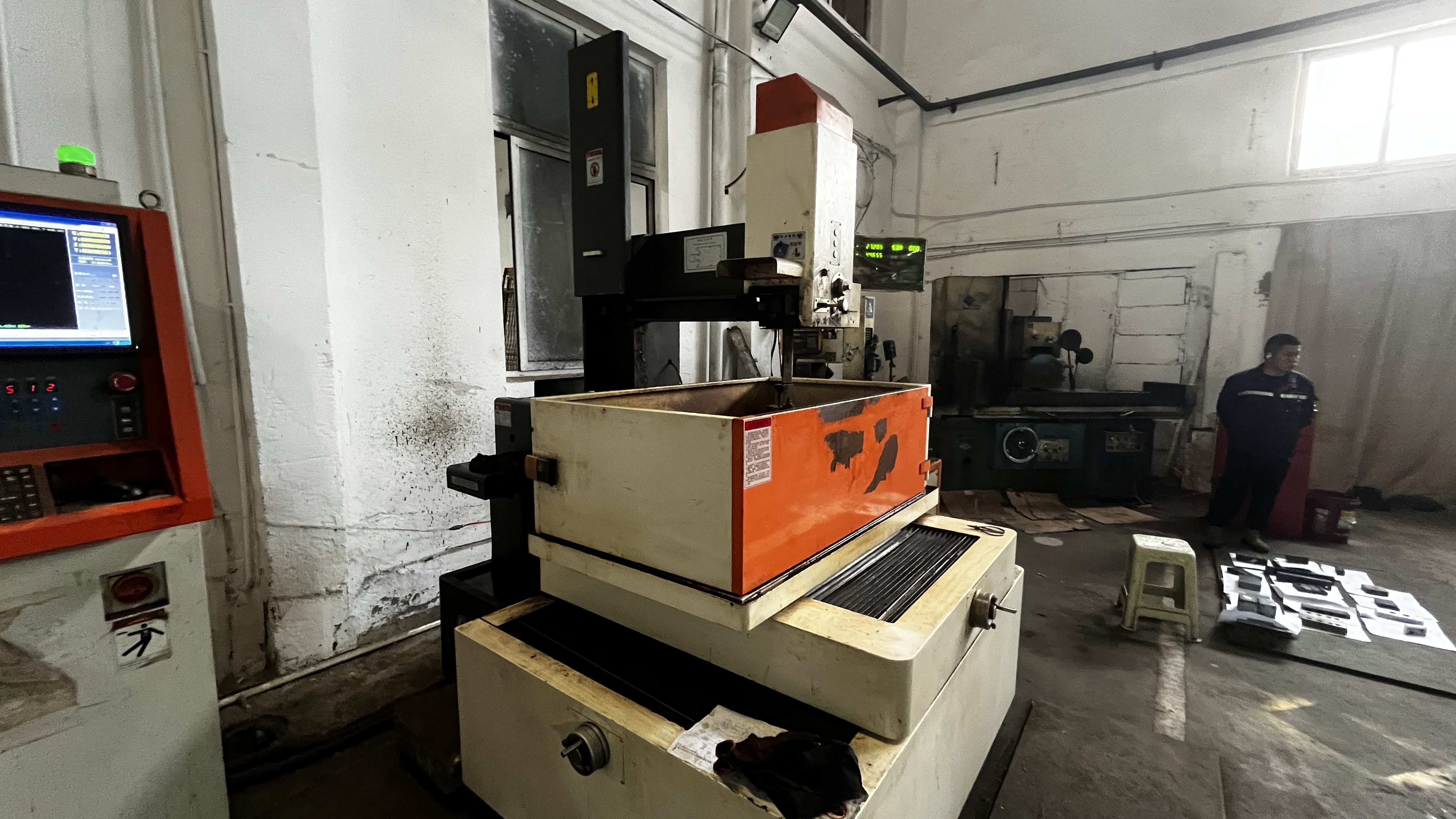
Car stamping dies are crafted using advanced machining techniques such as CNC milling, EDM, and grinding. The process starts with a finalized die design, followed by precise shaping of raw materials into durable dies. These tools are then heat-treated and surface-finished to ensure they can withstand high-pressure sheet metal forming, delivering accurate, repeatable parts for automotive manufacturing.
2. What is the difference between a stamping die and a progressive die?
A stamping die is a general term for any tool that shapes or cuts metal in the stamping process. A progressive die is a specific type that performs multiple operations in sequence as the material moves through different stations, ideal for high-volume production. In contrast, single-hit or compound dies complete one or a few operations per press stroke, often used for simpler or lower-volume parts.
3. What are the key factors to consider when selecting a stamping die type for automotive parts?
Choosing the right die type depends on part complexity, required tolerances, production volume, and surface quality needs. Progressive dies suit high-volume, multi-featured parts, while transfer and draw dies handle large or deep-formed panels. It's also important to assess maintenance requirements, changeover complexity, and how each option fits your manufacturing process.
4. How do maintenance practices impact the lifespan of stamping dies?
Regular maintenance—such as cleaning, edge inspection, re-sharpening, and sensor checks—extends die life and reduces unplanned downtime. Identifying wear early and addressing issues like galling or chipping through refurbishment or proper lubrication helps maintain consistent quality and lowers long-term operational costs.
5. Why is CAE simulation important in the automotive stamping die process?
CAE simulation allows engineers to model material flow, predict forming defects, and optimize die geometry before production begins. This reduces tryout cycles, minimizes costly rework, and ensures that stamping dies deliver precise, high-quality parts from the start. Collaborating with a partner who uses CAE and holds certifications like IATF 16949 can further enhance process reliability and part quality.