 Small batches, high standards. Our rapid prototyping service makes validation faster and easier —

Manufacturing Die Build Steps That Shrink Cost And Lead Time
Essential Concepts and Definitions
Ever wondered how everyday metal parts—from car doors to kitchen appliances—get their precise shapes and features? The answer lies in the world of the manufacturing die, a cornerstone of modern production. If you’ve heard terms like tool and die or press tool but aren’t sure what they mean, you’re not alone. Let’s break down the essentials so you can navigate deeper design and manufacturing topics with confidence.
What is a Manufacturing Die?
A die is a precision tool designed to cut or shape material in a press, ensuring repeatability and dimensional accuracy in mass production.
In practical terms, a manufacturing die is a custom-shaped piece of tooling—usually made from hardened steel—that transforms flat sheet metal, wire, or softer materials into finished parts. Dies are not stand-alone; they work as part of a die set, which includes key components like the punch (which moves), die block (which holds the material), stripper (to remove the part), guide elements, and mounting plates. Together, these elements form the heart of a press tool system.
Where Tool and Die Work Fits in Production
So, what is tool & die versus just a die? In manufacturing, tool and die work refers to the broader discipline of designing, building, and maintaining all specialized tools—including dies, molds, jigs, and fixtures—that enable mass production. While a die is the shaped element that forms or cuts material, tool and die covers the full workflow: from design and machining to setup and troubleshooting.
Dies are typically installed in mechanical or hydraulic presses on the production floor. Here, they perform repeated operations with tight tolerances, ensuring every part matches the design. This is central to high-volume industries like automotive, electronics, and consumer goods.
Core Functions: Blanking, Piercing, Forming, and More
Imagine you’re making a car fender or a metal bracket. What are dies used for in these cases? The answer lies in their core operations, which fall into two main categories:
- Blanking: Cutting a flat shape (the blank) from sheet metal
- Piercing: Punching holes or slots into the sheet
- Forming: Bending or shaping the metal without removing material
- Drawing: Stretching the metal into a deeper shape (like a cup or shell)
- Trimming: Removing excess material for precise edges
Each of these operations may require a different die design, but all rely on the same principles of controlled force and alignment. For example, die cutting is essential in industries where speed and accuracy are paramount, as it allows for high-throughput production with minimal waste.
| Die Type | Typical Parts Produced | Common Materials |
|---|---|---|
| Blanking Die | Automotive brackets, electronic enclosures | Steel, aluminum, brass |
| Piercing Die | Ventilation holes, mounting slots | Sheet metal (various alloys) |
| Forming Die | Body panels, appliance covers | Low-carbon steel, stainless steel |
| Drawing Die | Cups, cans, shells | Aluminum, steel |
| Trimming Die | Finished edges on stamped parts | Varies by application |
Key Elements and Safety Considerations
Every die set must be precisely aligned in the press to ensure proper shut height and set height. Incorrect setup can lead to tool damage or safety risks. Operators must always follow safety protocols during setup and operation, as the forces involved are significant. Proper maintenance and alignment guarantee long tool life and consistent part quality.
In summary, understanding what is a die in manufacturing—and how it fits within the broader tool and die field—lays the groundwork for mastering advanced topics in die design, build, and troubleshooting. As you explore the next chapters, you’ll gain deeper insight into how the right die architecture, materials, and processes can shrink cost and lead time without sacrificing quality.
Types of Dies and When to Use Them
When you walk through a busy manufacturing floor, you’ll notice that not all stamping dies are created equal. In fact, selecting the right die type can make or break your project’s cost, speed, and quality. But how do you know which die architecture fits your part? Let’s break down the major types of dies used in sheet metal processes—and when each shines.
Progressive vs Transfer Die Selection
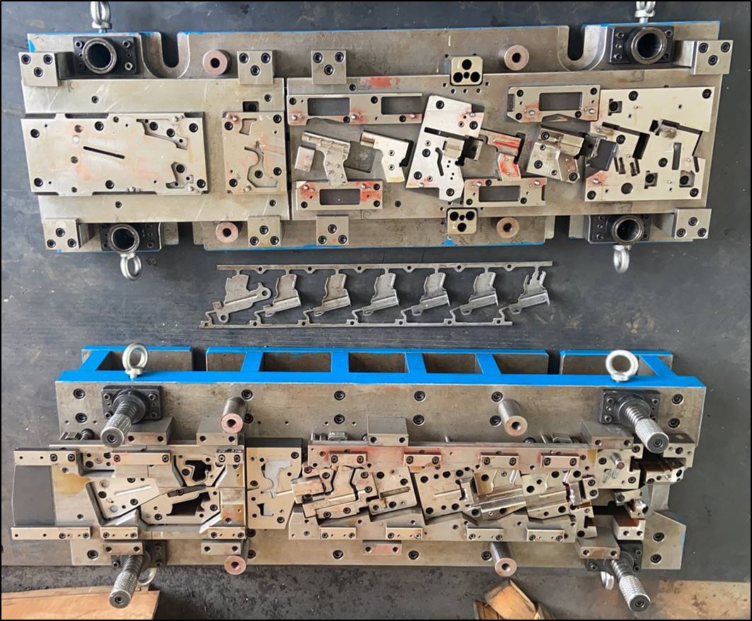
Imagine you need thousands of identical metal brackets, each with several holes and bends. This is where a progressive die excels. In a progressive die setup, sheet metal feeds continuously from a coil through a series of stations—each performing a unique operation like piercing, forming, or trimming. The part is completed as it exits the final station. Progressive dies are best for high-volume runs of moderately complex parts, where speed and efficiency matter most. However, they require a higher initial investment and meticulous maintenance to keep every operation in sync.
On the other hand, transfer dies are like an assembly line for larger or more intricate parts. Here, the part is moved—either mechanically or manually—from one station to the next. Each station can perform a different operation, making transfer dies flexible for complex shapes and deeper draws. This method suits medium to high production volumes but comes with higher setup and operational costs due to the complexity of the transfer system.
| Die Type | Part Complexity | Tolerance Needs | Feed Type | Expected Volume | Maintenance |
|---|---|---|---|---|---|
| Progressive Die | Medium | High | Coil | High | Frequent |
| Transfer Die | High | Medium | Blank/Coil | Medium-High | Frequent |
| Compound Die | Low | High | Blank | Low-Medium | Low |
Compound and Line Dies Use Cases
For simpler, flat parts like washers or electrical contacts, compound dies are often the go-to solution. A compound die performs multiple operations—such as cutting and punching—in a single press stroke. This makes them ideal for low- to medium-volume production where precision is key but part geometry is straightforward. Maintenance is generally lower due to the simpler design, but these dies are limited when it comes to complex shapes.
Line dies are used when each operation (blanking, piercing, forming, etc.) is performed in separate dies, often in sequential presses. This setup is flexible for large parts or when combining multiple die types is necessary, but it typically results in slower throughput and more manual handling.
Forming and Draw Dies at a Glance
When it comes to deep shapes—think automotive door inners or reinforcement panels—forming dies and tools like draw dies are essential. These dies gradually shape the metal, controlling material flow to avoid tearing or excessive thinning. The choice between a simple forming die and a more robust draw die depends on the depth and geometry of your part, as well as the material’s behavior under stress. For example, deep drawing requires careful attention to draw ratios and the addition of features like draw beads to control metal movement.
- Progressive dies: Best for brackets, high-volume reinforcement parts
- Transfer dies: Suited for door inners, complex body panels
- Compound dies: Ideal for flat, simple parts like washers
- Forming/draw dies: Needed for deep shells, automotive structural parts
Ultimately, the selection of dies types hinges on your part’s complexity, required tolerances, production volume, and how the material behaves under forming. By understanding these distinctions, you’ll be equipped to choose the right press dies and die press setup for your application—laying the groundwork for efficient manufacturing and quality outcomes.
Next, we’ll explore how material and heat-treatment choices further influence die performance and cost, ensuring your metal stamping dies deliver lasting value.
Die Materials, Heat Treatment, and Coatings
When you invest in a manufacturing die, have you ever wondered why some tools last for years while others wear out quickly or crack under pressure? The answer often lies in the careful selection of die material, heat treatment, and surface engineering. Let’s break down how these choices directly impact die longevity, cost, and your production’s bottom line.
Selecting Die Steel for Blanking and Forming
Imagine you’re specifying a steel die for high-volume blanking, or a tooling die for forming ultra-high-strength steel. The right die steel must balance toughness (resisting cracks and chipping) and wear resistance (standing up to abrasion and galling). According to die engineering best practices, you should always start by considering the most likely failure mode in your application—will your metal die fail by cracking, chipping, or wearing away?
Select for the failure mode you most need to prevent.
For example, D2 tool steel is a popular cold-work choice thanks to its high wear resistance, but it can be prone to chipping if subjected to shock loads. S7, on the other hand, offers excellent toughness, making it ideal for operations where impact is a concern. For hot-work applications—think die casting or forming at elevated temperatures—H13 is a go-to material because it maintains hardness and resists thermal fatigue. Carbides and powdered metal tool steels are reserved for extreme wear zones, but their higher cost means they’re best used where the return on investment is clear (The Fabricator).
| Material Family | Toughness | Wear Resistance | Typical Application |
|---|---|---|---|
| D2 (Cold-work) | Medium | High | Blanking, piercing, moderate forming |
| S7 (Shock-resistant) | High | Medium | Piercing, trimming, dies with impact loading |
| H13 (Hot-work) | Medium | Medium | Die casting, hot forming |
| Carbide/Powdered Metal | Low-Medium | Very High | High-wear inserts, abrasive materials |
Beyond the steel itself, always factor in the number of parts you expect to run, the workpiece material’s hardness, and the complexity of the die forming operation. Sometimes, using a more expensive steel die up front can reduce maintenance and downtime, resulting in lower total cost over the die’s life.
Coatings and Surface Engineering Choices
Ever seen a die that starts to gall or stick to the workpiece? That’s where surface engineering steps in. Techniques like nitriding and PVD (Physical Vapor Deposition) coatings—including TiN or AlCrN—are widely used to create a hard, wear-resistant surface that resists galling, adhesive wear, and corrosion. Duplex surface engineering, which combines nitriding and a PVD coating, is especially effective for extending the life of dies in challenging environments. This dual approach not only improves wear resistance but also reduces downtime for maintenance.
- Nitriding: Adds a hard, wear-resistant layer by diffusing nitrogen into the surface—ideal for dies needing high surface hardness without distortion.
- PVD Coatings: Deposits thin, ultra-hard films that reduce friction and resist wear. Common choices include TiN (gold color), TiAlN, and AlCrN.
- Duplex Engineering: Combines both for superior performance, especially in automotive, packaging, and medical die forming applications.
When choosing coatings, consider the compatibility with your base die material and the operating temperature. Some coatings require high-temperature processes that may soften certain steels, so always verify with your supplier or consult standards.
Heat Treatment Sequencing and Stress Relief
Heat treatment is the backbone of die manufacturing, directly affecting dimensional stability and performance. For hot-work steels like H13, industry standards such as NADCA, FORD, and GM specify vacuum heat treatment with controlled quenching rates and multiple tempering cycles to ensure uniform hardness and minimize internal stresses (SECO/WARWICK). Proper heat treatment includes:
- Gradual preheating to avoid thermal shock
- Controlled austenitizing and rapid quenching (often in vacuum furnaces with gas quench)
- Multiple tempering cycles for stress relief and dimensional stability
Monitoring temperature differences between the core and surface of large dies is crucial—excessive gradients can cause cracking or distortion. Simulation tools and real-time thermocouple monitoring are now common in advanced die engineering to predict and control final properties during die manufacturing.
Through-hardening (hardening the entire cross-section) is typical for high-performance dies, while case hardening (hardening only the surface) is used when core toughness is required. The choice depends on the demands of your specific die process.
By aligning your die material, heat treatment, and surface engineering strategy with the realities of your production—part material, run rate, and expected wear modes—you’ll maximize die forming performance and extend tool life. Next, we’ll explore how to design your die for manufacturability, ensuring stable production and long-term value.
Design for Manufacturability for Dies
When you’re tasked with die design, it’s tempting to focus on part geometry and material specs alone. But have you ever run into costly rework or inconsistent parts during production? That’s where Design for Manufacturability (DFM) comes in—bridging the gap between the drawing board and stable, high-yield manufacturing. Let’s walk through the practical DFM guidelines that keep your sheet metal die projects on track, minimize scrap, and extend die life.
Blanking and Pierce Clearance Fundamentals
Ever noticed rough edges or excessive burrs after a punch drawing operation? The culprit is often improper clearance. Punch and die clearance—the gap between the punch and die button—directly controls cut quality, burr formation, and die tooling wear. Here’s what you need to know:
- Clearance grows with material thickness. Thicker materials require greater clearance to avoid excessive force and premature tool wear.
- Material hardness matters. Harder or higher-tensile materials need larger clearances to prevent die chipping or punch breakage.
- Recommended clearance is typically 10% of material thickness per side for standard applications, but modern practices suggest 11–20% for tougher materials or longer tool life.
- Burr direction is predictable: Burrs form on the side of the material that exits the die opening. Plan your die drawing and part orientation accordingly.
Proper clearance not only ensures clean edges but also reduces secondary deburring and extends the life of your die tooling.
Edge Radii and Bead Strategies for Springback
Have you ever bent a part only to find it “springs back” and doesn’t hold the intended angle? That’s springback—a common headache in forming dies and tools. Here’s how to manage it:
- Larger die radii reduce splitting and cracking but increase springback. There’s always a trade-off between formability and dimensional accuracy.
- Springback is more pronounced in high-strength and thinner materials. Always test with actual production material before finalizing the die form.
- Draw beads and addendum shapes help control metal flow—they “lock” the material in place and reduce springback variation across the part.
- Angle compensation and overbending are standard techniques: Intentionally bend past the final angle, letting springback bring the part into spec.
Modern die process strategies may include real-time angle control systems or feedback devices to further stabilize results, especially in automated production lines.
Tolerancing and Datum Schemes that Work
Ever been asked to hold "tight tolerances everywhere"? In die design, that’s a trap. Instead, focus on what really matters:
- Critical features get tight tolerances. Secondary features can often be loosened, saving cost and avoiding unnecessary die complexity.
- Datum selection should mirror how parts are measured and assembled. The best die drawing references the same datums used in metrology and downstream assembly.
- Follow general tolerances like ISO 2768 for non-critical features, but always confirm with customer requirements and house standards.
Collaborate early with your team to identify which features truly drive part function and fit. This approach streamlines die tooling and reduces tryout loops.
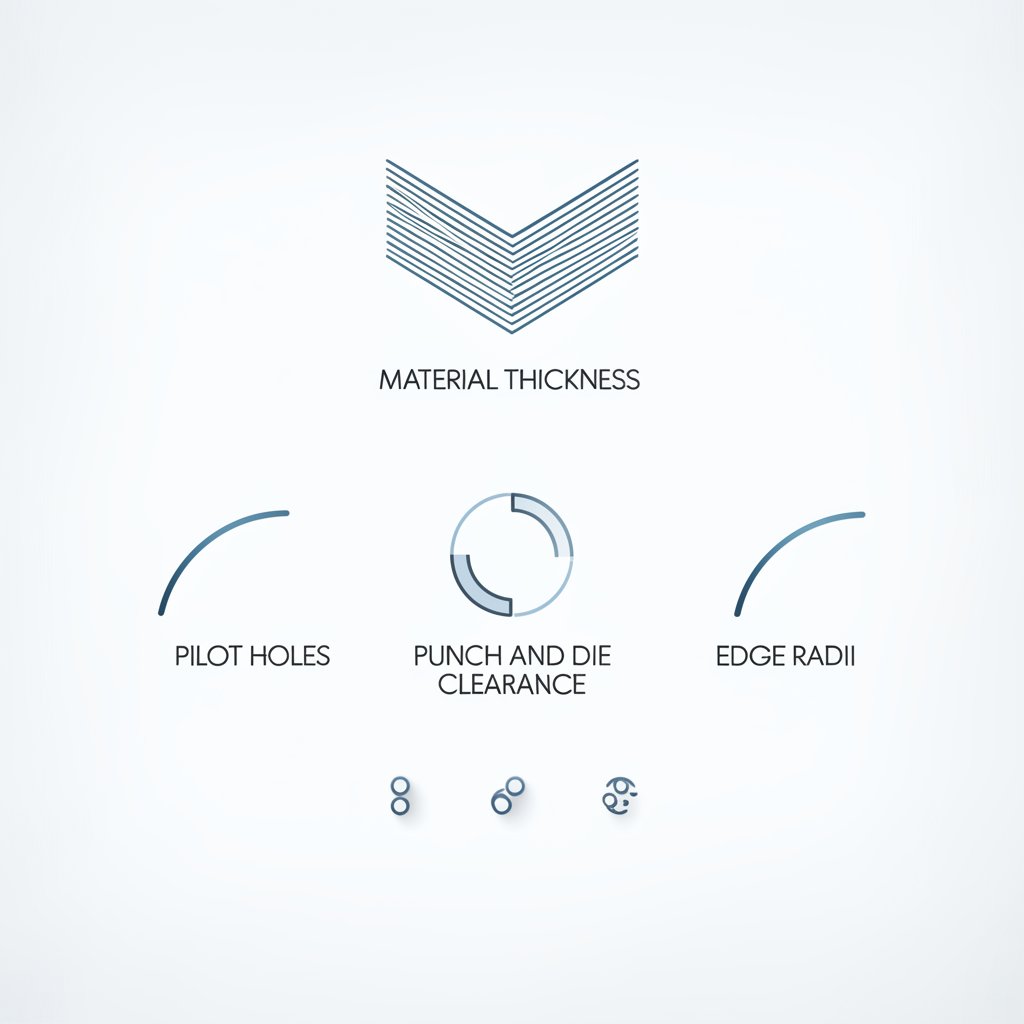
Stepwise DFM Checklist for Die Design
Ready to apply these principles? Here’s a practical checklist to guide your next die process:
- Analyze material thickness and grade—are you using production-intent stock?
- Specify punch and die clearance based on material and thickness.
- Design edge radii and draw beads to manage springback and prevent splitting.
- Check hole and feature proximity—avoid clustering features too close to edges or bends.
- Plan pilot hole locations for accurate strip progression in progressive dies.
- Set tolerances and datum schemes that match how parts will be measured and assembled.
- Review the complete die drawing with production, quality, and tooling teams before release.
Control variation at the strip to stabilize downstream forming.
By following these DFM rules, you’ll create forming dies and die tooling that deliver consistent results, minimize rework, and keep your manufacturing die process efficient. Up next, we’ll dive into the step-by-step manufacturing of the die, showing how these design choices translate into real-world build quality and performance.
Manufacturing the Die Step by Step
Ever wondered why some dies deliver flawless parts for years, while others struggle with accuracy or wear out quickly? The answer often lies in the precision and discipline of the die build process. If you’re new to stamping die manufacturing or looking to refine your approach, let’s break down the essential steps and best practices that shape a high-performance manufacturing die—from digital design to final tryout.
CAM Toolpaths for Die Cavities
Imagine you’ve finished a robust die design. What’s next? The journey begins with computer-aided manufacturing (CAM) to translate your CAD model into actionable toolpaths. Here’s how the process unfolds:
- CAD and CAE Validation: Engineers create a 3D model of the die, then run simulations to predict material flow and potential trouble spots. This step ensures the machine die will meet dimensional and performance targets.
- Material Preparation: High-strength steel or alloy blocks are cut to size. If required, the stock undergoes heat treatment to achieve baseline hardness and toughness.
- Rough Machining: Using CNC machining centers, excess material is removed to create the basic die shape. Conservative stock is left for later finishing steps, accounting for any potential distortion during heat treatment.
- Semi-Finish and Stress Relief: After roughing, the die is partially machined to near-final dimensions, then stress-relieved to minimize internal stresses. This helps prevent warping during subsequent steps.
- Finish Machining: Precision CNC machining creates the final contours, critical features, and tight tolerances. Here, advanced 5-axis machining dies technology shines—enabling complex shapes and high repeatability.
Throughout these steps, maintaining consistent datums and locator schemes is critical. This ensures that all features align perfectly—whether you’re machining dies for automotive panels or intricate electronic parts.
EDM Electrode Strategy and Tolerancing
Some die features—like deep pockets or sharp internal corners—can’t be milled conventionally. That’s where Electrical Discharge Machining (EDM) comes in. But how do you optimize this step?
- Electrode Design: Electrodes (often graphite or copper) are custom-shaped to match the cavity or feature. Multiple electrodes may be used: roughing electrodes for fast material removal, and finishing electrodes for final precision.
- EDM Machining: The electrode is brought close to the die block, and controlled sparks erode the material to the desired shape. The process is tuned for speed (higher energy for roughing) or surface finish (lower energy for finishing).
- Tolerancing and Undersize Strategy: Electrodes are often made slightly undersize to compensate for the spark gap—ensuring the finished cavity matches the CAD model. The exact undersize depends on machine and material, but the principle is to plan for the EDM gap in both roughing and finishing steps.
Proper flushing and dielectric fluid management are essential to avoid arcing and maintain surface quality. Advanced EDM systems may use adaptive controls for real-time gap adjustments, further improving accuracy.
Fixturing and Assembly Best Practices
After machining and EDM, it’s time to bring the die together:
- Hand Fitting and Polishing: Skilled technicians refine the die’s surface finish, ensuring smooth material flow and eliminating minor imperfections.
- Die Assembly: All die components—including punches, buttons, guides, strippers, and springs—are assembled with precision. Alignment is checked against the original datums established in the CAD phase.
- Tryout and Adjustment: The assembled die is installed in a press for test runs. Parts are measured for dimensional accuracy and surface finish. If needed, minor tweaks are made—such as adjusting shut height or refining radii.
| Die Component | Function |
|---|---|
| Punch | Shapes or pierces the material during the press stroke |
| Die Button | Works with the punch to define holes or cutouts |
| Guide Pin/Bushing | Ensures precise alignment between die halves |
| Stripper | Removes the part from the punch after forming or cutting |
| Springs/Gas Cylinders | Provide controlled force for stripping or part ejection |
Each component must be installed and checked meticulously. Even a small misalignment can cause premature wear or part defects, emphasizing why careful assembly and inspection are non-negotiable in die machining.
By following this disciplined build sequence, you not only improve accuracy and tool life but also lay the groundwork for reliable, repeatable production. Next, we’ll explore how thorough inspection and tryout processes ensure your die is truly production-ready—helping you avoid costly surprises down the line.
Quality Assurance Inspection and Tryout
When you’ve invested time and resources into a new manufacturing die, the last thing you want is a surprise defect or a costly production delay. So, how do you make sure your dies and stamping processes deliver consistent, high-quality results from the very first part? Let’s walk through a practical quality plan—covering first-article inspection, measurement strategies, and tryout documentation—that keeps your tool and die manufacturing on track and your production risk low.
First Article and Buyoff Checklist
Imagine launching a new die: your first step is a First Article Inspection (FAI). This comprehensive review checks that the entire process die—from raw material to final part—matches design intent and is ready for serial production. According to industry best practices, an FAI should include:
- Design records (drawings, BOMs, ballooned drawings)
- Raw material certificates and traceability
- Dimensional inspection reports (with gage IDs and calibration records)
- Special processing certifications (e.g., heat treatment, coatings)
- Functional test results
This process isn’t just a box to check—it’s your opportunity to catch design or process issues early, ensuring that each subsequent part will meet expectations. If you change the part design, process, or supplier, a new FAI is required to validate those changes (1Factory).
Measurement Points and Gaging Strategy
Sounds complex? Not if you break it down. To ensure reliable die processing, every critical feature must have a clear inspection plan. The golden rule:
Measure what you locate.
That means aligning your datums and checks with how the part is held and used in the real world. A robust gaging strategy includes:
- Go/no-go gages for quick functional checks
- Variable gages (calipers, micrometers, CMMs) for key dimensions
- Repeatable and traceable measurements—each tied to a specific gage and calibration record
- Coverage of features that drive assembly, fit, and performance
Don’t forget: gage resolution should be at least one-tenth of the feature tolerance to ensure accuracy. This attention to detail is what separates robust tool and die manufacturing from trial-and-error approaches.
Tryout Logs and Corrective Actions
Once your die is assembled and initial parts are produced, tryout is where theory meets reality. During tryout, document every adjustment, measurement, and outcome. Key inspection artifacts include:
- Strip layout and material flow maps
- Pierce quality and burr direction notes
- Springback measurements and compensation records
- Panel flushness and gap checks
- Surface finish and cosmetic assessments
Each observation helps you fine-tune the die, ensuring consistent results when you move to full production. Use a tryout log to record:
- Date and shift
- Operator and press settings
- Die adjustments made
- Non-conformances and corrective actions taken
To make quality control more actionable, pair common defect types with inspection methods and acceptance criteria:
| Defect Type | Inspection Method | Acceptance Criteria |
|---|---|---|
| Burr Height | Micrometer, visual check | Meets print spec or visual standard |
| Hole Position | CMM, go/no-go gage | Within specified tolerance |
| Springback | Angle measurement, CMM | Within allowable angle deviation |
| Surface Finish | Profilometer, visual | Meets cosmetic/roughness standard |
Finally, don’t overlook process capability monitoring. By tracking process capability indices (like Cpk) for key features, you can proactively spot trends before they become problems. This is the backbone of any ISO 9001-aligned quality management system for dies and stamping operations.
With a clear quality plan, measurement strategy, and tryout documentation, you’ll minimize launch risk and set the stage for stable, high-yield production. Next, we’ll tackle troubleshooting and preventive maintenance—ensuring your die delivers lasting performance shift after shift.
Troubleshooting and Preventive Maintenance
When you’re staring at a pile of rejected parts or an idle press, it’s easy to wonder: what went wrong with the die? Whether you’re a seasoned tool & die maker or just starting out, knowing how to systematically diagnose and maintain your die sets is the key to reliable, cost-effective production. Let’s break down the most common failure modes, how to fix them, and the shop-floor routines that keep your manufacturing die in top shape.
Diagnosing Burrs and Edge Quality
Ever noticed ragged edges or burrs on your stamped parts? Burrs are more than a cosmetic issue—they signal trouble in the punch die and can lead to downstream assembly problems or even safety hazards. Here’s a quick guide to root causes and corrective actions:
- Worn punch or die edges—often from lack of sharpening or improper material selection.
- Incorrect punch-to-die clearance—too tight leads to galling, too loose causes rollover and large burrs.
- Misalignment in the die for press or mounting base, resulting in uneven wear or double impressions.
Pros and Cons: Increasing Clearance
- Pros: Reduces punch and die wear, lowers press tonnage, helps with thicker or harder materials.
- Cons: Can increase burr height if excessive, may reduce edge quality for thin materials.
Pros and Cons: Re-sharpening Punches/Buttons
- Pros: Restores clean cutting action, improves edge quality, extends die life.
- Cons: Requires downtime and skilled labor, repeated sharpening reduces tool dimensions over time.
Regular visual checks and timely re-sharpening are essential. According to industry best practices, always follow a direction check during die installation and adjust stamping depth incrementally to avoid excessive wear.
Solving Misfeeds and Strip Control Issues
Imagine the frustration of a misfeed: strips jam, parts misalign, or the press plate stops mid-cycle. These issues don’t just waste material—they risk damaging your tooling dies and halting production. Common culprits include:
- Improper strip guides or worn pilots, leading to inaccurate progression.
- Build-up of debris or lack of lubrication causing material drag.
- Incorrect press settings or worn springs/gas cylinders in the die set.
Pros and Cons: Adding or Tuning Pilots
- Pros: Improves strip alignment, reduces misfeeds, stabilizes part progression in progressive dies.
- Cons: Adds complexity and cost, requires precise installation and maintenance.
Pros and Cons: Improving Lubrication
- Pros: Reduces friction, prevents galling, extends tool and die life.
- Cons: Over-lubrication can cause contamination or slippage, may require additional cleaning steps.
Establishing a routine for cleaning, lubricating, and inspecting strip guides and pilots is a simple way to avoid costly downtime. Always use shims and calibration checks to ensure precise alignment.
Wear, Cracking, and Regrind vs Replace
Premature wear, cracking, or chipping in your die maker tools can shut down production fast. But how do you know when to regrind and when to replace?
| Failure Symptom | Likely Root Cause | Preventive Step |
|---|---|---|
| Burrs, rough edges | Worn punch/die edges, improper clearance | Sharpen edges, check/adjust clearance |
| Cracks in punch or die | Improper heat treatment, overloading, misalignment | Review heat treat records, check alignment, avoid overloading |
| Chipping of punch corners | Excessive hardness, sharp internal corners, improper steel choice | Use tougher steel, add radii, review design |
| Premature wear (galling, scoring) | Poor lubrication, incorrect material pairing, surface finish issues | Improve lubrication, apply coatings, polish surfaces |
| Misfeeds, double hits | Strip misalignment, worn guides/pilots | Replace guides, re-align die set |
Root-cause analysis is critical: don’t just fix the symptom—trace it back to design, material, heat treatment, or setup. As VA C AERO notes, multiple factors often contribute, and a thorough review of design, material, and process history is best practice.
Preventive Maintenance Checklist for Die Sets
Imagine never being surprised by a sudden die failure. That’s the power of a disciplined preventive maintenance routine. Here’s a practical checklist to keep your tooling dies and die sets in optimal condition:
- Schedule regular visual inspections for cracks, wear, and misalignment (focus on punch edges, die buttons, guides, and stripper plates).
- Sharpen punches and dies at the first sign of edge rounding or burrs—don’t wait for part quality to drop.
- Clean and lubricate all moving parts, including guide pins and bushings, to prevent galling and scoring.
- Check fastener torque and stripper/pressure pad balance to avoid uneven wear or shifting during operation.
- Inspect and replace springs or gas cylinders as needed to maintain consistent stripping force.
- Keep detailed maintenance logs—record inspection intervals, findings, and actions taken.
- Establish clear criteria for when to regrind (minor wear, no cracks) versus replace (deep cracks, excessive wear, repeated failures).
Don’t forget: well-maintained dies are safer, more reliable, and deliver better part quality. Proactive care is a hallmark of every great tool & die maker and extends the life of your investment.
By following these troubleshooting and maintenance strategies, you’ll stabilize uptime and boost the performance of every die for press on your floor. Up next, we’ll explore how smart tooling economics and lifecycle planning can help you budget and schedule for even greater efficiency.
Tooling Economics and Lifecycle Planning
When you’re planning a new manufacturing die, it’s easy to focus on the sticker price. But have you ever considered how the right economic strategy can turn a higher upfront investment into lower long-term costs and smoother production? Let’s break down the key factors that shape tooling economics, so you can plan budgets, timelines, and maintenance with confidence—whether you’re an engineer, a sourcing manager, or a die manufacturer looking to sharpen your edge in the die industry.
Cost Drivers and Tradeoffs
Imagine you’re comparing two tooling quotes: one for a basic single-operation die, the other for a robust progressive die with advanced features. Why such a big difference? The answer lies in several core cost drivers:
| Feature/Upgrade | Impact on Upfront Cost | Impact on Per-Part Cost | Impact on Lifecycle/Maintenance |
|---|---|---|---|
| Premium Tool Steel or Carbide Inserts | High | Lower (over long runs) | Longer tool life, fewer stoppages |
| Advanced Coatings (e.g., PVD, Nitriding) | Medium | Lower (reduces wear/scrap) | Less regrind, better uptime |
| Additional Die Stations | High | Lower (higher throughput) | More complex maintenance |
| In-Die Sensors | Medium | Lower (prevents crashes) | Early fault detection, fewer breakdowns |
| Quick-Change Features | Medium | Lower (less downtime) | Faster changeovers, higher flexibility |
Lower per-part cost often follows better die stability.
For example, investing in premium tool steel or advanced coatings may seem costly at first, but if you’re running hundreds of thousands of parts, the reduction in downtime, scrap, and maintenance can pay off quickly. On the flip side, for short runs or prototype projects, simpler or even soft tooling may be the smarter financial move (The Fabricator).
Run Rate and Break Even Planning
Ever wondered when a progressive die makes more sense than a line die? It often comes down to production volume and part complexity. Here’s how to approach it:
- Low Volume (Prototypes, <10,000 parts): Lower-cost, simpler dies or soft tooling are often best. The initial investment is lower, even if per-part costs are higher.
- Mid Volume (10,000–100,000 parts): More durable tools (hardened steel), with some automation or progressive features, strike a balance between cost and efficiency.
- High Volume (>100,000 parts): Advanced dies (progressive or transfer) with automation, premium materials, and robust maintenance plans drive the lowest per-part cost.
Break-even analysis helps you decide: Will the higher upfront spend on a complex die be offset by lower operating costs over the expected run? If the answer is yes, the investment is justified. If not, consider a simpler approach. This is a core principle in what is tool and die manufacturing—matching die architecture to production goals and budget.
Maintenance Scheduling and Spare Strategy
Imagine your line is down, waiting for a replacement punch. That’s where lifecycle planning comes in. Proactive maintenance and a well-stocked spare kit are essential for minimizing costly downtime. Here’s how to structure your approach:
- Set preventive maintenance (PM) intervals based on expected wear—track tool life data and schedule sharpening or regrinding before issues occur.
- Keep critical spares (punches, buttons, springs) on hand, especially for high-volume dies where even short delays are expensive.
- Document all maintenance actions and part replacements—this builds a data-driven history for future cost and downtime forecasting.
- Coordinate with your die manufacturer or supplier to ensure quick turnaround on custom or long-lead parts.
Well-planned PM and spares not only extend die life but also support stable production and predictable costs—hallmarks of top-tier industrial tool die and engineering operations.
Build-Versus-Buy Analysis: A Simple Framework
- Define your production volume, part complexity, and quality requirements.
- Estimate total cost of ownership for in-house tooling vs outsourced dies (include build, maintenance, and downtime).
- Assess supplier capabilities and lead times—are they experienced in your part type and volume?
- Factor in ongoing support: Will the supplier provide spare parts, maintenance, and engineering help?
- Decide based on total value, not just lowest upfront price.
By weighing these considerations, you’ll make informed decisions that fit your budget, schedule, and production goals—whether you’re a buyer, engineer, or decision-maker in the die industry. Next, we’ll explore how to select the right automotive die partner to further streamline your project from prototype to mass production.

Selecting the Right Automotive Die Partner
When you’re tasked with bringing a new automotive die into production, the right partner can mean the difference between a seamless launch and unexpected delays. But with so many die manufacturing companies out there, how do you choose a supplier who will deliver precision, speed, and support at every stage? Let’s walk through a clear, actionable framework for vendor selection—then see how advanced simulation and engineering support can shrink cost and lead time in even the most demanding automotive programs.
What to Ask a Die Partner
Imagine you’re evaluating several die manufacturers for your next project. What should you look for beyond just a competitive quote? Here’s a practical checklist of due diligence questions to help you uncover true capability and fit:
- Do you hold relevant certifications (such as IATF 16949) for automotive die production?
- What is your experience with similar parts—especially complex body die or high-strength sheet metal dies?
- Can you provide end-to-end support, from die design and CAE simulation to tryout, launch, and ongoing maintenance?
- How do you approach formability analysis and dimensional control during the design phase?
- What is your process for virtual tryouts or simulation-driven optimization?
- How do you document and communicate design changes, process risks, and corrective actions?
- Can you scale production if volumes increase or design changes occur late in the program?
- Do you offer transparent project management, touchpoints, and on-site visits?
As industry experts recommend, thorough evaluation of experience, certifications, technical capabilities, and communication practices is essential for selecting a partner who will meet your requirements and adapt as your project evolves.
CAE Simulation and Tryout Reduction
Ever wonder how leading die manufacturing companies consistently deliver parts that meet tight tolerances—often on the first tryout? The answer is advanced CAE (Computer-Aided Engineering) simulation. By digitally modeling material flow, springback, and potential defects, top suppliers can predict and resolve issues before a single tool is cut. This dramatically reduces the number of physical tryout loops, shortens lead time, and cuts costs associated with rework or late-stage changes.
For example, Shaoyi Metal Technology stands out by combining IATF 16949 certification, advanced CAE simulation, and a collaborative engineering team. Their process includes:
- Virtual die tryouts to optimize die geometry and material flow
- In-depth formability analysis to anticipate and prevent defects in sheet metal dies
- Structural reviews to ensure robust, repeatable auto die production
- Support from rapid prototyping through to mass production
This integrated approach not only accelerates launch but also helps maintain dimensional accuracy and durability for critical body die components—attributes that are increasingly vital in today’s automotive industry (Keysight).
| Supplier | CAE Simulation | Engineering Support | Certifications | Launch & Aftercare |
|---|---|---|---|---|
| Shaoyi Metal Technology | Advanced, in-house; virtual tryouts | Full collaboration, formability & structural reviews | IATF 16949 | From prototype to mass production; global support |
| Hatch Stamping Company | Innovative software, CMM validation | In-house engineering, hands-on project management | ISO 14001/IATF 16949 | Custom solutions, ongoing repair & support |
| Other Die Manufacturers | Varies; some outsource simulation | Depends on team size & process maturity | Check for relevant industry standards | May offer limited launch or aftercare |
From Prototype to Mass Production
When you select a die partner with proven simulation, engineering, and launch capabilities, you’ll notice smoother transitions from early prototypes to full-scale body die production. This end-to-end approach is especially valuable for automotive projects, where late-stage changes or material shifts can otherwise derail schedules. The right supplier will not only build your tool but also act as an extension of your engineering team—troubleshooting, optimizing, and supporting your manufacturing die over its entire lifecycle.
In summary, choosing among die manufacturing companies isn’t just about price—it’s about finding a partner who can guarantee quality, speed, and adaptability. By prioritizing CAE-driven design, robust certifications, and clear communication, you set your next auto die project up for success. Ready to take the next step? Explore more about Shaoyi Metal Technology’s automotive die solutions as a benchmark for what is possible in today’s competitive landscape.
Manufacturing Die FAQs
1. What's the difference between tool and die in manufacturing?
A tool is any device used to perform actions like cutting or bending materials, while a die is a specialized tool designed to shape or form materials with high accuracy, often enabling the mass production of consistent parts.
2. What are the main types of dies used in manufacturing?
Key types include progressive dies for high-volume, multi-step operations; transfer dies for complex, large parts; compound dies for simple, flat parts; and forming or draw dies for shaping deep or intricate components.
3. How do material and heat treatment choices affect die performance?
Selecting the right die steel and heat treatment enhances wear resistance, toughness, and lifespan. Surface coatings like nitriding or PVD further reduce wear and galling, ensuring reliable, long-lasting die performance.
4. What should be included in a quality plan for die manufacturing?
A robust quality plan covers first-article inspection, clear measurement strategies, documented tryout logs, and ongoing process monitoring to maintain consistent part quality and minimize production risks.
5. How do I choose the right die manufacturing partner for automotive projects?
Look for partners with relevant certifications (like IATF 16949), advanced CAE simulation capabilities, comprehensive engineering support, and a track record of delivering precise, durable dies for automotive applications.