 Small batches, high standards. Our rapid prototyping service makes validation faster and easier —

Sheet Metal Stamping Dies: 10 Essential Points Engineers Miss
Stamping Die Fundamentals Made Clear
What is Metal Stamping and Why It Matters
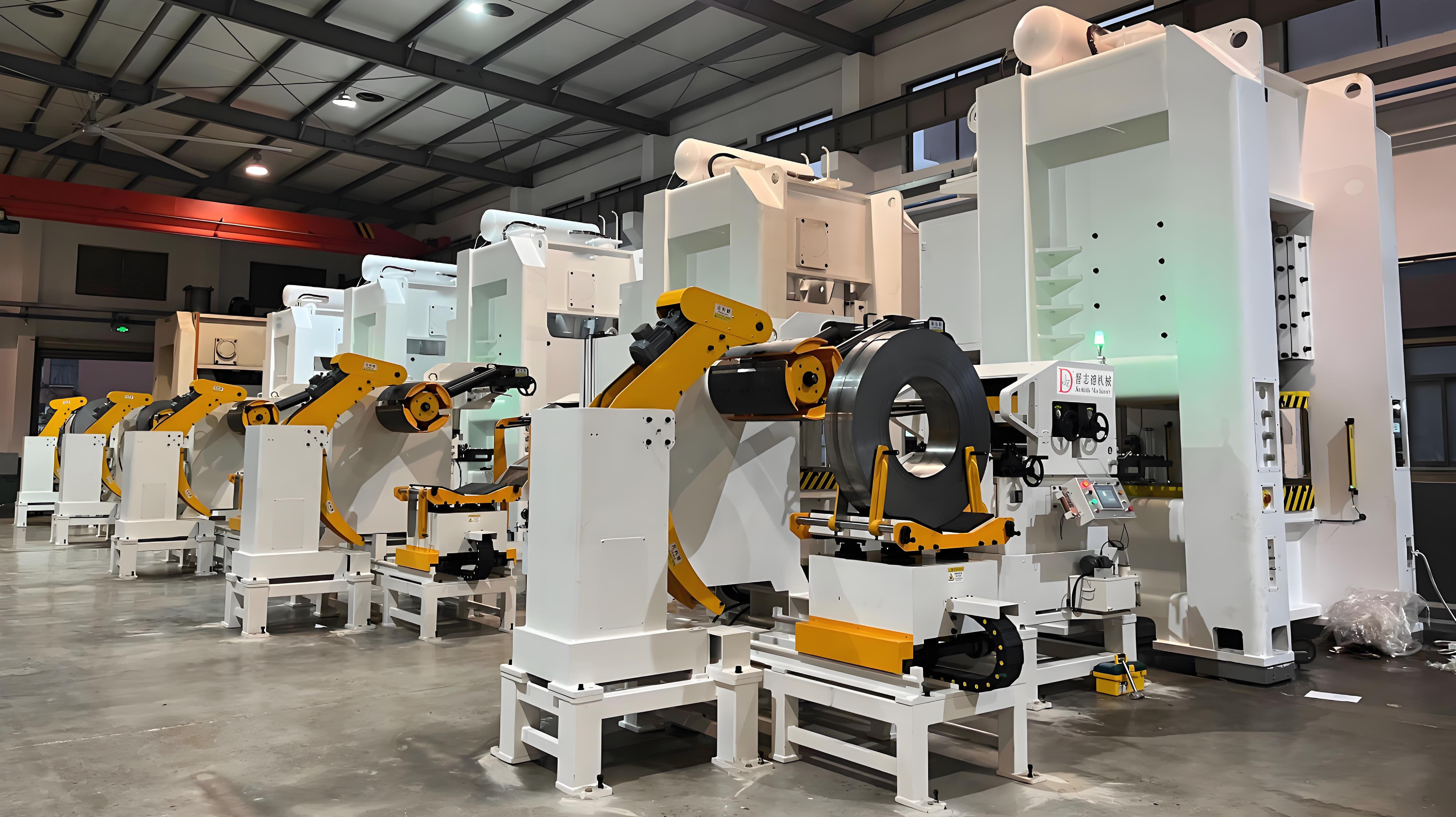
Ever wondered how a flat piece of metal transforms into a car bracket, appliance panel, or intricate electronic part? That’s the power of metal stamping. In its simplest form, metal stamping is a cold-forming process where a sheet or coil of metal is fed into a press and shaped by a tool called a stamping die. The press applies immense force—often measured in tons—pushing the die into or through the sheet to create precise, repeatable parts, all without the need for heat.
So, what is stamping in manufacturing terms? It’s a collection of processes—blanking, forming, drawing, piercing, flanging, and trimming—each performed by a stamping die to turn raw metal into functional components. The accuracy, speed, and cost-effectiveness of these operations make stamping essential for high-volume production across automotive, electronics, and appliance industries.
What a Stamping Die Does in the Press
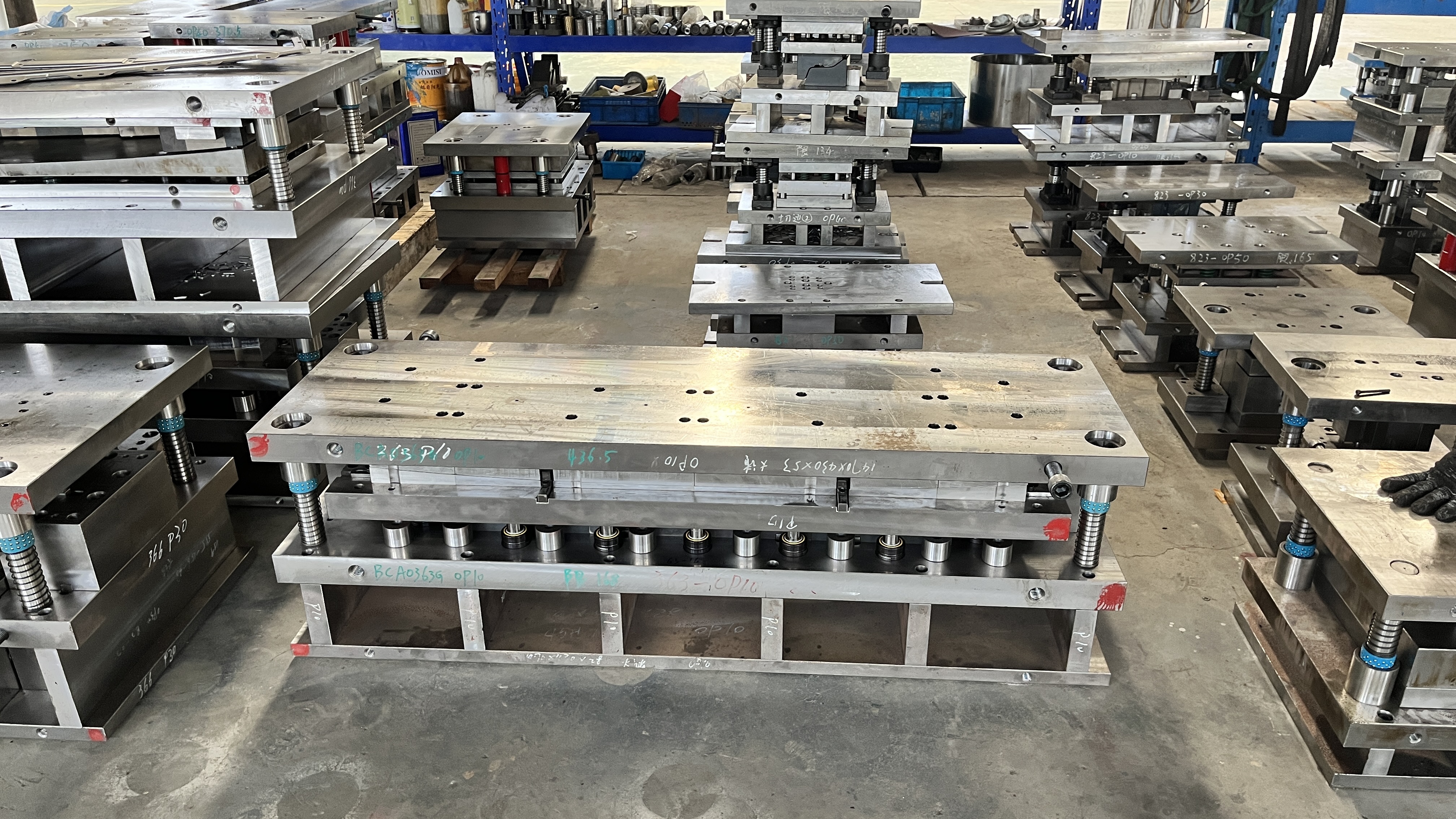
Imagine the stamping die as a custom mold for metal parts. When mounted in a press, it acts like a precision tool—cutting, forming, and shaping the metal exactly as designed. Dies are engineered for specific tasks. Some cut out shapes (blanking), others punch holes (piercing), while more advanced dies can form bends, curves, or even deep drawn cups.
- Blanking: Cutting out a flat shape from the sheet
- Forming: Bending or shaping the metal
- Drawing: Pulling the metal into a cavity to create depth
- Piercing: Punching holes or slots
- Flanging: Creating raised edges or lips
- Trimming: Removing excess material for a clean finish
Die quality amplifies or limits press capability; precision in the die is precision in the part.
From CAD to Coil to Finished Parts
Sounds complex? Here’s how the typical workflow unfolds:
- Part Design: Engineers create the geometry in CAD software, considering function, manufacturability, and cost.
- Die Design: Toolmakers design the stamping die, selecting die set materials and defining clearances based on the part’s geometry and metal type.
- Build: Skilled machinists fabricate the die, assembling core components—die plates, punches, buttons, springs, and retainers.
- Tryout: The die is tested in the press, with adjustments made to ensure part accuracy and repeatability.
- PPAP/Approval: Parts are validated to customer and industry standards before full production.
- Production: The approved die stamp is run in high volumes, producing thousands or millions of parts.
- Maintenance: Regular inspection, repair, and reconditioning keep the die and press performing at peak efficiency.
Key Die Components and Terminology
Let’s break down a few essential terms to align engineers, buyers, and operations teams:
- Die Set: The structural foundation holding all die components, typically upper and lower plates.
- Working Steels: The actual cutting and forming elements—punches and dies—that contact the metal.
- Subsystems: Elements like strippers (remove the part from the punch), pilots (align the material), lifters (raise parts or scrap), and sensors (monitor process or part presence).
Each subsystem plays a role in stamping meaning: precision, safety, and efficiency. For example, strippers prevent the metal from sticking to the punch, while sensors can detect misfeeds before a costly crash.
Why Materials and Geometry Matter
Not all metal stamping dies are created equal. The type of metal (steel, aluminum, copper) and the complexity of the part’s shape directly influence die geometry, clearances, and even the type of die used. Tight tolerances or intricate bends may require special working steels or advanced die configurations, which we’ll explore in detail later.
At its core, the stamping die is the bridge between design and production reality. Understanding its structure and function is the first step to mastering quality, throughput, and cost in any stamping project.
Next, we’ll dive into the different types of stamping dies and how to choose the right one for your application.
Choosing the Right Type of Stamping Die for Your Project
Progressive Dies for Continuous Coil-to-Part Flow
When you’re planning high-volume production and need a fast, repeatable process, progressive die metal stamping often stands out. Imagine a metal coil feeding into a press, moving from one station to the next in a single die set—each stroke advances the strip, and each station performs a different operation. The finished part is separated at the final station, ready for use. This method is ideal for complex parts with multiple features, such as brackets with holes, bends, and cutouts, all completed in a single, streamlined process.
Progressive dies require higher upfront investment and careful engineering. However, their speed and efficiency make them the go-to choice for producing thousands or even millions of identical parts. You’ll notice that the per-part cost drops dramatically as volume increases, making this stamp die type extremely cost-effective for long runs.
Compound and Stage Dies for Discrete Operations
Not every part needs the complexity of a progressive die. For simpler, flat components—think washers, gaskets, or simple brackets—compound die stamping is often the answer. Here, multiple operations (like cutting and punching) are performed in a single press stroke, but without the sequential movement of material through stations. This approach is efficient for low-to-medium volumes and excels at delivering high-precision flat parts.
Stage or line dies, meanwhile, break down the process into separate stations, with the part moved manually or by automation between dies. This method offers flexibility for parts that might need unique operations at each stage, but it can increase setup time and handling costs.
Transfer Dies: Flexibility for Larger and Complex Parts
What if your part is large, has deep draws, or requires complex features not easily handled by the other die types? Transfer dies step in. In this process, the part is physically transferred (by mechanical arms or automation) between separate die stations, each performing a specific function. Transfer dies shine when you need to form intricate shapes or larger components that progressive dies can’t accommodate efficiently.
| Die Type | Best For Volumes | Typical Operations | Setup Time | Scrap Rate Potential | Maintenance Complexity |
|---|---|---|---|---|---|
| Progressive | High | Multi-feature, sequential | High (initial) | Low | High (many moving parts) |
| Compound | Low to Medium | Simple, flat parts | Low | Low | Low to Medium |
| Transfer | Medium to High | Large/complex, multi-step | High | Medium | High (complex transfer systems) |
| Stage/Line | Low to Medium | Step-by-step, flexible | Medium | Medium | Medium |
How Components Inside Dies Drive Performance
Regardless of the types of dies you choose, the performance and longevity of your stamp and die setup depend on the quality and configuration of its key components. These are the unsung heroes inside every die:
- Punches: Cut or form features into the sheet metal
- Dies: Matched to punches, providing the cavity or shape
- Pilots: Align material for precise feature placement
- Strippers: Remove the part or scrap from the punch
- Pressure Pads: Hold the workpiece steady during forming
- Lifters: Raise parts or scrap for transfer
- Cams: Enable side actions or angled features
For example, if your part has multiple piercings or deep draws, you’ll need more stations in a progressive die or additional cam actions in a transfer die. The right combination of stamping die components ensures your process remains stable, efficient, and cost-effective.
Choosing the right stamp die is about matching part complexity, volume, and downstream needs to the die’s strengths—there’s no one-size-fits-all solution.
As you evaluate your options, consider not just the initial investment, but also how each die type impacts maintenance, scrap, and flexibility. Up next, we’ll discuss how material selection further shapes your die design and performance.
Material Specific Die Design Rules for Sheet Metal Stamping
Ever noticed how some stamped sheet metal parts look flawless, while others warp, crack, or wear out tools far too quickly? The secret often lies in matching your die design to the unique behavior of each material. Whether you’re working with aluminum, HSLA or stamped steel, stainless, or copper alloys, the right approach can slash tryout cycles and field failures. Let’s break down what you need to know for each group—and why skipping these details can cost you in both quality and efficiency.
Designing Dies for Aluminum Without Galling
Aluminum’s lightweight strength and corrosion resistance make it a favorite for automotive, aerospace, and electronics. But the aluminum stamping process brings challenges like galling (material sticking to dies), oxide buildup, and shrinkage during piercing. Here’s a practical checklist for aluminum stamping success:
- Blank Holder Force: Use moderate force—too high increases thinning, too low causes wrinkling.
- Die Radii: Increase radii versus steel to reduce cracking and thinning; sharper corners risk splits.
- Tool Coatings: Apply coatings (e.g., TiN, chrome) to minimize galling and prolong tool life.
- Lubrication: Choose fully synthetic, oil-free lubricants designed for both light and heavy-duty stamping. Proper lube reduces friction and galling.
- Punch-to-Die Clearance: Adjust based on aluminum grade and thickness—softer grades require tighter clearance to avoid burrs and shrinkage.
- Surface Finish: Maintain smooth, polished tooling to limit oxide buildup and sticking.
Aluminum’s springback can be unpredictable, so validate compensation strategies with tryout parts before locking fixtures. Also, consider the impact of the chosen alloy—5000 and 6000 series handle piercing better, while 3000 and 4000 series are prone to shrinkage and require careful clearance adjustment.
Dialing in Stamped Steel Edge Quality
Stamped steel sheet is the backbone of automotive and industrial parts, prized for its strength and cost-effectiveness. But with increased strength comes reduced formability and a higher risk of springback, splits, and excessive tool wear. Here’s how to optimize your approach for steel stamping dies (Auto/Steel Partnership):
- Blank Holder Force: Increase force for HSLA and ultra-high strength steels; insufficient force leads to buckling or wrinkles.
- Die Radii: Use as small a radius as the material allows—1 to 2 times sheet thickness for lower strength, slightly larger for high strength. Smaller radii reduce springback but risk splits if too tight.
- Draw Beads: Tune bead location and shape to control metal flow, especially for deep draws. Run beads out at tangent points to avoid corner splits.
- Tool Coatings and Materials: Upgrade to wear-resistant tool steels and consider chrome plating for high-volume or outer panel work.
- Lubrication: Use lubricants formulated for extreme pressure. Pre-lubes or dry films may be needed for advanced grades.
- Die Clearance: Maintain 7–10% of metal thickness for HSLA; tighter clearance improves edge quality but increases wear.
For stamped steel components, springback compensation is crucial—plan for overbend (up to 6 degrees for HSS) and validate with forming analysis or CAE simulation. Don’t forget to adjust radii and clearances for different grades within the stamped steel sheet family.
Stainless Steel and Copper: Special Considerations
Stainless steel excels where corrosion resistance and strength are critical, but it work-hardens rapidly and can be tough on dies. Copper and its alloys, meanwhile, are go-to materials for electrical components due to their excellent conductivity but can be prone to burrs and require gentle forming.
| Parameter | Stainless Steel | Copper/Brass |
|---|---|---|
| Blank Holder Force | High (to prevent wrinkling) | Low to Moderate (minimize work hardening) |
| Die Radii | Larger radii to avoid cracking | Small, but avoid sharp corners |
| Tool Coatings | Wear-resistant (e.g., nitrided, carbide) | Standard tool steel, polished finish |
| Lubricant Viscosity | High—aggressive lubrication required | Low to medium—prevent burrs |
| Die Clearance | Increase slightly for hard grades | Optimize for minimal burr, avoid excessive work hardening |
For both groups, maintain a focus on surface finish—polished dies help reduce friction and sticking. For copper, keep forming operations minimal to avoid excessive work hardening, and always check for burrs on sheet metal stampings destined for electrical use.
Adjust springback compensation strategy by material grade and thickness; validate with tryout parts before locking fixtures.
Why Material-Specific Tuning Matters
Imagine skipping these adjustments: more scrap, longer tryouts, and unhappy customers. By tailoring your die design, clearances, and process controls to the material—whether it’s aluminum, stamped steel, stainless, or copper—you’ll boost part quality and tool life, and minimize surprises in production. Don’t hesitate to leverage CAE/formability analysis to predict issues like splits and wrinkles and to fine-tune draw bead geometry for each material.
Next, we’ll explore how to translate these material-driven rules into quantitative die design and press selection for robust, efficient stamping lines.
Quantitative Design And Press Selection
Clearance and Punch-to-Die Fit Fundamentals
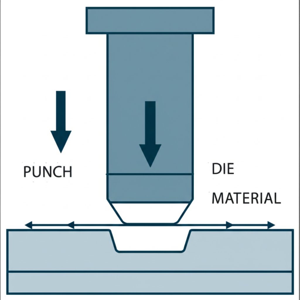
Ever wondered why some stamped parts come out crisp and clean, while others show burrs or require constant rework? The secret often lies in the punch-to-die clearance—a core pillar of stamping die design. Clearance is the gap between the cutting edge of the punch and the die opening. Too tight, and you risk excessive wear or broken tools; too loose, and you get rough edges and burrs that add cost and slow down production.
- Standard Rule: Clearance is typically set as a percentage of sheet thickness—often 10% per side for mild steels, with harder or thicker materials requiring more.
- Material Matters: Stronger, harder materials (like high-strength steel) need larger clearances, while softer metals (like aluminum) can use less.
- Quality vs. Tool Life: Tighter clearance improves edge quality but increases punch/die wear and alignment demands. Wider clearance extends tool life but may create more burrs.
Here’s a quick formula for calculating per-side clearance:
Clearance per side (%) × Material Thickness = Actual Clearance (per side)
For example, with a 2 mm thick steel sheet and a recommended 10% clearance, the gap is 0.2 mm per side. Adjust as material, part tolerance, or tool wear dictates.
Press Tonnage Estimation and Energy Needs
Choosing the right press is about more than just "bigger is better." Imagine underestimating the force needed—your die and stamping process could stall or damage equipment. Overestimate, and you waste energy and capital. For sheet metal die work, you’ll need to calculate both the required tonnage and the press’s energy capacity.
For blanking and piercing, use:
Required Tonnage = Perimeter × Material Thickness × Shear Strength
- Perimeter: Total length of the cut edge (in inches or mm)
- Material Thickness: In inches or mm
- Shear Strength: In tons/in2 or N/mm2
For drawing or forming operations, swap in the material’s ultimate tensile strength. Don’t forget to add extra for spring strippers, lifters, cams, and scrap cutting. And always check that the press can deliver the energy needed at the point in the stroke where the load peaks (The Fabricator).
Sounds complex? Try mapping each station’s load, then sum them for total press requirements. This not only protects your die and stamping investment but ensures balanced loads and longer tool life.
Station Planning and Progressive Advantages
How do you decide the number and order of stations in a die-stamping machine? Each feature—holes, bends, trims—needs its own stop. Progressive dies shine here, letting you combine multiple steps in one tool. The result? Faster production, less handling, and more consistent quality. In fact, the primary advantage of a progressive press is its ability to deliver continuous, repeatable throughput with minimal manual intervention.
| Station | Operation | Feature Quality Checkpoint |
|---|---|---|
| 1 | Blank | Edge quality, flatness |
| 2 | Pierce | Hole diameter, burr height |
| 3 | Form/Draw | Bend angle, draw depth |
| 4 | Trim | Final profile, edge burrs |
| 5 | Flange | Flange angle, length |
| 6 | Restrike | Dimensional accuracy |
Each station serves as a controlled checkpoint for quality and dimensional accuracy. Smart station planning minimizes rework and helps operators quickly spot issues before they escalate.
Integrating It All: Practical Steps for Success
- Start with material specs and part geometry to set initial clearances.
- Estimate tonnage for each operation and sum for total press requirement.
- Choose a press with both the tonnage and energy capacity needed for your die and stamping workload.
- Lay out stations to match each feature, optimizing for progressive flow when possible.
- Validate with tryouts and adjust as needed—small changes in clearance or sequence can have big impacts on quality and tool life.
Balancing clearance, tonnage, and station layout is the foundation of robust stamping die design—optimize these, and you’ll unlock stable, cost-effective production for any sheet metal die.
Next, we’ll look at how process controls and troubleshooting strategies keep your stamping line running smoothly, even when the unexpected happens.
Lubrication Control And Troubleshooting in the Sheet Metal Stamping Process
Ever had a stamped part come out with wrinkles, cracks, or stubborn burrs—despite careful die design? You’re not alone. Even the best-engineered sheet metal stamping dies can run into trouble if process controls or lubrication aren’t dialed in. Let’s break down the essentials for keeping your stamping process stable, your dies healthy, and your parts defect-free.
Lubrication Strategies for Draw, Pierce, and Flange Operations
Imagine you’re running a high-speed stamping line. If you notice lubricant pooling under the press or parts coming out with inconsistent finishes, it’s a red flag. Proper lubrication isn’t just about picking the right oil—it’s about applying it consistently and in the right amount. The wrong lubricant or poor application can lead to increased friction, tool wear, and even defects like splits or burrs (The Fabricator).
- Drawing/Deep Forming: Use high-lubricity, high-viscosity oils or synthetic lubricants. Apply evenly to both sides of the strip (contact applicators like rollers/wipers work best).
- Piercing/Blanking: Moderate-viscosity lubricants, targeted at the cutting zone. Non-contact spray systems can be effective, but watch for overspray and waste.
- Flanging/Bending: Lighter lubricants or dry films may suffice, especially for simple bends. Ensure coverage at bend radii to prevent galling.
- Material Matters: Aluminum and stainless need more aggressive lubrication to avoid galling; copper and brass require just enough to prevent burrs and surface stains.
Cleaner shop floors, less scrap, and longer tool life are all signs you’ve got lubrication under control. If you’re seeing lubricant on the floor or in scrap bins, it’s time to revisit your application method.
Rapid Troubleshooting for Splits, Wrinkles, Burrs, and More
When defects appear, don’t panic—systematic troubleshooting can quickly get your stamping and pressing line back on track. Here’s a practical table you can use on the shop floor:
| Symptom | Likely Causes | Corrective Actions |
|---|---|---|
| Wrinkles | Low blank holder force, uneven strain, improper lube, loose material | Increase holder force, adjust lube, check material thickness/fit |
| Cracks/Splits | Excessive strain, sharp radii, poor lube, improper die clearance, hard material | Increase radii, improve lube, check clearance, use softer material |
| Excessive Burrs | Worn or dull punch/die, excessive clearance, poor lube, misalignment | Regrind/replace tooling, adjust clearance, improve lube, realign die |
| Flares/Edge Rollover | Improper punch/die fit, worn tools, excessive lube | Check punch/die fit, replace tools, reduce lube amount |
| Shock Line Stamping Defect | Sudden press speed change, uneven feed, lube breakdown, material lot variation | Stabilize press speed, calibrate feed, check lube system, review material batch |
For every stamping metal process, it’s critical to document each change—only alter one variable at a time, and record the outcome. This disciplined approach prevents confusion and helps you zero in on root causes rather than chasing symptoms.
Stabilizing the Sheet Metal Stamping Process
What’s the secret to a stable, high-yield stamping and die cutting operation? It’s less about heroics and more about controlling inputs and monitoring for drift. Instability often starts with:
- Material lot variability (thickness, hardness, surface finish)
- Lubrication breakdown (wrong type, inconsistent application, clogged nozzles)
- Feed misalignment or slippage
- Poor scrap evacuation (leading to jams or double feeds)
Stabilize inputs—coil properties, lube application, feed accuracy—before altering die geometry.
For example, if you’re seeing a sudden rise in burrs or splits, first confirm your lubricant is being applied correctly and your coil stock is within spec. Only after stabilizing these factors should you consider adjusting die clearances or station order.
Sometimes, restrike operations can be used to correct minor form defects, but this comes at a cost—added cycle time and tool wear. It’s better to address root causes upstream whenever possible.
Best Practices for Process Control
- Standardize lubricant application and inspection at each shift change.
- Use checklists for die setup and shutdown to ensure consistency.
- Monitor part quality at each station—catch issues early, before they propagate.
- Keep clear records of all adjustments and outcomes for future troubleshooting.
By combining robust process control with targeted troubleshooting, you’ll reduce downtime, scrap, and tool wear—unlocking the full potential of your sheet metal stamping process.
Next, we’ll see how automation and real-time monitoring can take defect prevention and process stability to the next level.
Automation and Industry 4.0 in Stamping
Press Monitoring and In-Die Sensing: The Foundation of Smart Stamping
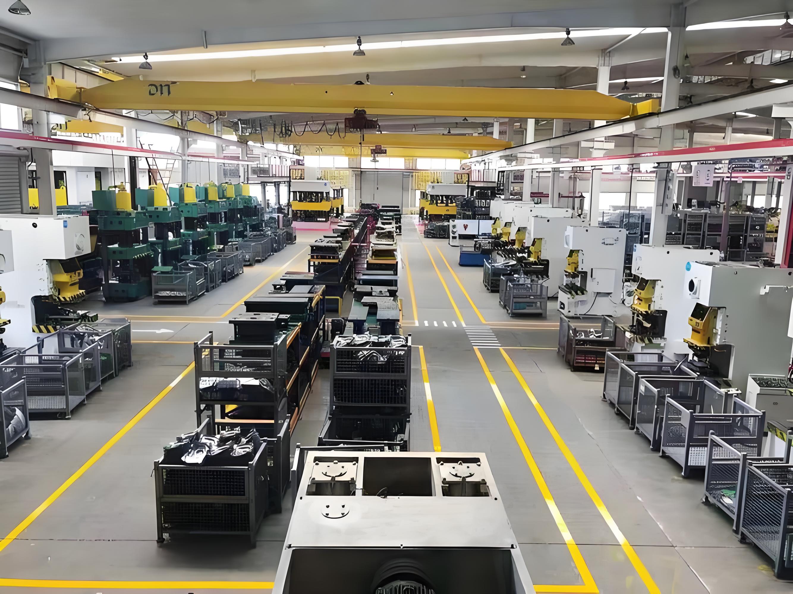
When you picture a modern die stamping machine in action, do you imagine a hands-off, highly automated line producing flawless parts hour after hour? That’s no longer just a vision—it’s reality, thanks to the integration of sensors and real-time data capture in industrial metal stamping. But how do these technologies actually work, and what do they mean for your process?
Let’s start with the basics. Early automation relied on simple counters or manual checks. Today, advanced stamping technology leverages a suite of in-die sensors to monitor every critical step. These sensors not only protect the die from crashes and misfeeds but also create a controlled production environment that consistently delivers high-quality parts.
- Basic Stroke Counter: Tracks press cycles to schedule maintenance and monitor output.
- Tonnage Monitor: Measures force applied during each stroke—helps spot overloads or unexpected resistance.
- In-Die Sensors: Detect part presence, strip position, misfeeds, and more in real time.
- Vision Inspection: Uses cameras to verify part features, orientation, or detect defects on the fly.
- Closed-Loop Feed Corrections: Automatically adjusts feed or press parameters based on sensor feedback, minimizing scrap and downtime.
- Tonnage Sensors: Mounted on the press frame or tie rods to monitor forming forces.
- Stripper Sensors: Embedded in the stripper plate to confirm part ejection.
- Part-Out Sensors: Positioned at die exits to ensure every part is removed.
- Misfeed Sensors: Placed along the feed path to detect jams or double feeds.
Design for sensors from day one; retrofits are harder and less reliable.
Robotic Feeding and Part Transfer: Unlocking New Levels of Production Metal Stamping
Ever wondered how some lines run at breakneck speeds with barely a hiccup? The answer often lies in robotic handling. Automated feeders and robotic transfer arms streamline material movement, reduce manual intervention, and help maintain a steady flow through each standard die and station. Imagine the impact: fewer misfeeds, less die damage, and more consistent cycle times.
But there’s more to it than just speed. Robotic systems can be programmed for precise placement, orientation, and even complex part manipulation between stations. This flexibility supports more intricate die designs and enables technical stamping for parts with demanding tolerances or geometries. Plus, with fewer hands-on interactions, workplace safety improves and operators can focus on higher-level oversight.
Keep in mind, though, that robotic integration affects die and line design—pitch, station spacing, and guarding must all be considered up front. When done right, the result is a seamless, high-throughput production metal stamping system that adapts quickly to changing demands.
Predictive Maintenance and Data-Driven Uptime Gains
What if your line could tell you in advance when a tool needs attention—before a costly breakdown? That’s the promise of predictive maintenance, a hallmark of Industry 4.0 in industrial metal stamping. By analyzing sensor data—vibration, temperature, force, and cycle counts—maintenance teams can spot trends and intervene proactively.
Instead of relying solely on fixed schedules, you’ll align preventive actions with real-world equipment health. For example, a spike in press tonnage readings or abnormal vibration patterns might signal wear on a standard die or bearing, prompting inspection before a failure occurs. This approach minimizes downtime, extends tool life, and reduces emergency repair costs.
Here’s a quick visual of the maturity path for automation in stamping lines:
- Manual counters and basic press monitoring
- Automated tonnage and cycle tracking
- In-die sensors for real-time part and strip monitoring
- Vision inspection systems for automated quality control
- Closed-loop controls and predictive maintenance analytics
As you progress along this path, you’ll notice not only higher output and quality, but also a more agile and resilient operation—one that can quickly adapt to new product requirements or market shifts.
Why Embracing Smart Stamping Technology Matters
Integrating automation, sensors, and data analytics isn’t just about keeping up with trends. It’s about building a stamping operation that’s more consistent, cost-effective, and ready for tomorrow’s challenges. Whether your focus is on die stamping machine upgrades or full-scale Industry 4.0 transformation, the key is to start with scalable steps and design for integration from the outset.
With these technologies in place, you’ll be better positioned to reduce scrap, improve part quality, and maximize uptime—critical wins for any pressing and stamping operation. As you consider your next equipment or process upgrade, ask: How can smarter automation and data help you get ahead?
In the next section, we’ll dive into maintenance and rework strategies that keep your stamping dies—and your production line—operating at peak performance.
Maintenance Repair And Rework Playbook for Precision Die Stamping
Routine Inspection and Wear Mapping
Ever wondered why some stamping shops run for months without a hiccup, while others seem to battle surprise breakdowns? The answer often lies in disciplined die processing and a proactive maintenance mindset. Imagine catching a worn punch before it causes a batch of rejected parts, or spotting a misaligned lifter before it damages your die set. That’s the power of a robust inspection and maintenance routine—a cornerstone of the die making industry.
- Incoming Inspection: Assess dies as they return from the press. Look for obvious damage, wear, or contamination.
- Cleaning: Remove metal shavings, lubricant residues, and debris. Clean dies reveal subtle cracks or wear patterns that dirty ones hide.
- Visual Checks: Use good lighting and magnification to inspect working surfaces, edges, and alignment features. Check for cracks, galling, chipped punches, or worn radii.
- Functional Checks in Press: Run the die at low speed to confirm smooth operation. Listen for unusual noises or increased tonnage—these can signal hidden problems.
- Measurement Against Control Plan: Use gauges or CMM to verify critical dimensions and clearances. Compare to your control plan or last good part.
- Decision Gate (Repair/Rework/Replace): Based on findings, decide whether to regrind, adjust, or fully rebuild components. Prioritize work based on production needs and part quality impact.
- Documentation: Log every intervention and outcome. This builds a history for each die set, helping predict future maintenance and guide dies production planning.
Document every intervention; predictable dies are maintainable dies.
When to Repair Versus Rework
Not sure when to regrind a punch or when to send a die for full rebuild? Here’s a quick guide:
- Regrind Punches: When burrs increase or hole sizes drift out of spec, a quick regrind restores sharpness and dimensional accuracy.
- Polish Radii: If you spot galling or rough finishes on formed areas, polish the radii to reduce friction and extend tool life.
- Adjust Clearances: When parts show excessive burrs or require more press force, check and reset clearances to the original die for manufacturing specs.
- Replace Springs/Lifters: Weak or broken springs can cause misfeeds or part ejection failures—replace before they fail in production.
- Reblue and Spot: Use bluing compound to identify high spots, then hand-fit components for optimal contact and alignment.
If a die set exhibits multiple issues—say, chipped punches and misaligned guides—consider a full teardown and rebuild. For minor wear or a single out-of-spec feature, targeted rework is faster and more cost-effective. Always weigh the downtime and risk to part quality before making your call.
Spare Components and Change Management
Imagine you’re mid-run and a punch fails. If you have a labeled spare kit on hand, you’re back up in minutes. If not, you risk hours of downtime and missed shipments. That’s why the best stamping tooling programs standardize spare parts and change management:
- Keep carts stocked with common wear items: punches, springs, lifters, shims, and fasteners.
- Label and organize spares by die set and feature for quick access.
- Update documentation after each change—track which components were replaced, when, and why.
- Review spare usage regularly to spot trends and adjust inventory or maintenance intervals.
This approach not only speeds up repairs but also supports continuous improvement in precision die stamping operations, reducing the risk of ad hoc fixes and undocumented changes.
Optimizing Inspection Frequency and Wear Detection
How often should you inspect your dies? There’s no one-size-fits-all answer, but here are some practical guidelines:
- Material Abrasiveness: Harder or more abrasive materials (like stainless or high-strength steel) require more frequent checks.
- Stroke Counts: Schedule inspections based on the number of strokes or parts produced—high-volume dies may need daily checks, while low-volume tools can be inspected less often.
- Critical Features: Prioritize features that affect part function or customer specs for first-piece and ongoing checks.
- Feedback Loops: Use data from past repairs and part inspections to refine intervals and catch wear trends early.
By connecting inspection frequency to material and production realities, you’ll catch issues before they become costly failures—and help ensure every die stamped part meets spec.
Why Maintenance Discipline Matters
Sound maintenance isn’t just about preventing breakdowns—it’s about protecting uptime, dimensional stability, and your reputation for quality. Each well-maintained die set is a direct investment in reliable dies production and the overall health of your stamping operation.
As you refine your maintenance playbook, remember: documentation, standardization, and a proactive approach are your best tools for long-term success in the die making industry. Next, we’ll explore how smart procurement and cost control can amplify these maintenance wins for your entire stamping program.
Cost Drivers, ROI, and a Smarter Procurement Framework for Metal Stamping Dies
Tooling Cost Drivers That Buyers Must Know
When you’re tasked with sourcing sheet metal stamping dies, the price tag can be daunting. But have you ever paused to ask, “What’s really driving these costs?” Understanding the main cost drivers is your key to smarter negotiations and better ROI. Let’s break them down in a way that’s easy to compare:
| Cost Driver | Impact (Low/Medium/High) | Notes |
|---|---|---|
| Die Type/Complexity | High | Progressive dies cost more upfront; compound or simple dies are less expensive but may limit flexibility. |
| Material (Tool & Part) | Medium/High | Harder tool steels and exotic part materials increase both tooling and maintenance costs. |
| Number of Stations | Medium | More stations mean more complexity, higher build time, and greater maintenance needs. |
| Cams/Sensors | Medium | Essential for intricate features or process monitoring; add upfront and ongoing costs. |
| Coating/Surface Treatment | Low/Medium | Improves tool life and part quality; a wise investment for abrasive or high-volume jobs. |
| Tryout Effort | Medium | Complex parts or tight tolerances require more tryout cycles and adjustments before approval. |
| Spare Sets/Components | Low/Medium | Having spares reduces downtime but adds to initial investment. |
| Maintenance | High (over time) | Neglecting maintenance increases cost per metal stamping part—plan for scheduled upkeep. |
Each of these factors can shift your total cost of ownership. For example, investing in robust coatings or advanced sensors may raise initial costs, but they often pay for themselves by reducing unplanned downtime and scrap rates over the die’s lifetime.
Per-Part Cost and the Volume Crossover
Ever wondered why custom metal stamping dies can seem expensive up front, yet become a bargain at scale? The answer lies in how tooling costs are amortized across production. The more parts you make, the lower your per-part tooling cost becomes. But where’s the break-even point?
Let’s illustrate: If your die costs $50,000 and each metal stamping die part saves you $2 over a machined alternative, your payback is 25,000 parts. After that, every additional part lowers your total cost per unit. This is why high-volume programs can justify more complex, durable tooling—and why low-volume runs may stick with simpler dies or even other manufacturing methods.
But don’t overlook hidden costs: scrap rate, cycle time, maintenance, and changeover frequency all impact your true per-part cost. Efficient manufacturing stamping operations focus on reducing these variables, not just the sticker price of the die.
Vendor Selection Criteria and RFQ Tips
How do you ensure you’re getting the best value—not just the lowest price—from stamping die manufacturers or a stamping die factory? It starts with a clear, comprehensive RFQ (Request for Quotation). Here’s a checklist to keep you on track:
- Include fully dimensioned part prints with GD&T (Geometric Dimensioning & Tolerancing).
- Specify material type, grade, and thickness ranges.
- State annual volumes and expected peak rates.
- Outline your required quality plan (inspection points, certifications, traceability).
- Define packaging, labeling, and delivery requirements.
- Share your target launch timing and any critical milestones.
Why so much detail? The more information you provide, the more accurate and comparable your quotes will be. It also signals to suppliers that you’re serious about quality and long-term partnership. As you review quotes, look beyond price: consider supplier experience, technical support, lead times, and their ability to support ongoing maintenance and quick changeovers.
Connecting Engineering Choices to Financial Outcomes
Imagine you’re evaluating two die designs—one with a lower upfront cost, but higher scrap and maintenance, and another with a higher initial investment but proven longevity. Which is the better deal? Often, the second option wins in total ROI, especially for long runs or critical applications. That’s why collaborating early with your supplier on DFM (Design for Manufacturability) and robust tooling pays off in the long run.
Remember, the smartest buyers don’t just chase the lowest quote—they build partnerships that deliver quality, reliability, and cost savings across the full lifecycle of their metal stamping part programs.
Next, we’ll see how to objectively evaluate die suppliers for automotive and high-spec programs, ensuring your investment pays off from prototype to full production.

Selecting an Automotive Die Partner With Confidence
What to Evaluate in an Automotive Die Partner
When you’re sourcing automotive stamping dies, the stakes are high—dimensional accuracy, launch speed, and lifetime cost all ride on your supplier choice. But with so many metal stamping die manufacturers and service models, how do you objectively compare options? Imagine you’re preparing for a new automotive stamping process launch. You’ll want to look beyond price and check how each partner supports design, simulation, certification, and production scale-up. Here’s a comparative table to help you clarify your priorities:
| Vendor | CAE/Formability Support | Certification | Tryout Approach | Launch Services | Automotive References |
|---|---|---|---|---|---|
| Shaoyi Metal Technology | Advanced CAE simulation, in-depth structural and formability reviews, design optimization for automotive components progressive stamping | IATF 16949, global automotive compliance | Rapid prototyping, iterative tryout cycles, close engineering collaboration | Cross-functional launch support, PPAP documentation, mass production readiness | Trusted by 30+ global automotive brands |
| Precision Stamping Vendor A | Standard FEA/CFD analysis, limited DFM input | ISO 9001, some automotive experience | Conventional tryout, customer-driven adjustments | Basic launch support, on-request documentation | Multiple Tier 2/3 automotive programs |
| Global Die Group B | CAE via partner network, variable support | IATF 16949, multi-site | Batch tryout, remote engineering reviews | Standard PPAP, limited on-site launch | References in EU, APAC |
| Regional Toolmaker C | Manual reviews, little simulation | ISO 9001 | Traditional tryout, longer lead times | Minimal launch support | Local OEMs, niche projects |
How CAE and Formability Reviews Cut Tryout Time
Ever faced unexpected part splits or wrinkles during tryout? Early CAE (Computer-Aided Engineering) and formability reviews are your insurance policy. By running digital simulations of your custom metal stamping die before cutting steel, you can predict material flow, spot problem zones, and optimize geometry—often reducing tryout iterations and tooling costs. Modern CAE tools, including FEA and CFD, provide actionable feedback on stress, draw depth, and springback, letting you lock in robust designs earlier in the automotive die cutting process (Neural Concept).
For example, Shaoyi Metal Technology leverages advanced CAE simulation and cross-functional collaboration, helping teams validate and refine dies for automotive components progressive stamping before tryout. This not only accelerates launch but also enhances consistency and part quality—key advantages for high-volume automotive programs.
Certification and Launch Support Considerations
Certification isn’t just a box to check—it’s a critical risk management tool. When evaluating metal stamping die manufacturers, prioritize those with IATF 16949 or comparable automotive certifications. This ensures your supplier understands PPAP (Production Part Approval Process), traceability, and the documentation required for global launches. Ask about:
- Depth of launch support (on-site, remote, or hybrid)
- Experience with rapid prototyping and mass production transitions
- Proven track record with global automotive brands
Look for partners who offer transparent communication, robust documentation, and proactive issue resolution. These qualities reduce launch delays and help you hit your quality and timing targets.
Choosing the right automotive die partner means balancing technical capability, simulation-driven design, certification, and launch support—not just cost or proximity.
Tips for Confident Supplier Selection
- Visit facilities or request virtual tours to assess equipment, workflow, and capacity
- Review sample PPAP packages and ask for references from recent automotive stamping die projects
- Clarify expectations on communication, engineering change management, and post-launch support
- Weigh the value of early CAE and DFM involvement—these often pay for themselves in reduced rework and faster launches
By using a structured comparison and focusing on the full lifecycle of your automotive stamping die, you can select a partner who supports your goals from prototype to production. As you move forward, remember that robust supplier collaboration is the foundation for success in any automotive stamping process—and sets the stage for a data-driven, sustainable die program.
In our final chapter, we’ll outline a practical roadmap for integrating design, process control, and supplier selection into a winning stamping strategy.
Actionable Roadmap and Next Steps for Sheet Metal Stamping Dies
Build Your Die Program Roadmap
When you’re ready to take your stamping project from concept to production, where do you start? The process may seem overwhelming, but breaking it down into clear, manageable steps can make all the difference. Here’s a practical roadmap that connects design, process control, and procurement—ensuring your sheet metal stamping dies deliver on quality, cost, and timeline:
- Finalize Print and Material Specs: Review your part drawings for function, manufacturability, and cost. Confirm all tolerances, material grades, and thicknesses are realistic for the manufacturing stamping process.
- Choose Die Type and Stations: Match part complexity and volume to the right die (progressive, compound, transfer, or line). Define each operation—blanking, piercing, forming, trimming—within your sheet metal die press plan.
- Estimate Tonnage and Select Press: Calculate the force and energy needed for each operation. Select a press that provides the right tonnage, shut height, and bed size for your die and part.
- Validate with CAE/Formability: Use Computer-Aided Engineering (CAE) and virtual tryout tools to simulate material flow, predict splits or wrinkles, and optimize your die geometry before cutting steel. This step de-risks your project and shortens tryout time.
- Issue RFQ with Cost Drivers: Prepare a detailed request for quotation (RFQ) including part prints, material specs, annual volumes, and quality plans. Highlight your priorities—speed, cost, flexibility, or certification—to attract the right partners.
- Plan Tryout and PPAP: Schedule die tryouts and process validation runs. Use the Production Part Approval Process (PPAP) to lock in quality and gain customer approval before ramping up production.
- Lock Maintenance and Monitoring Plan: Set inspection intervals, spare parts lists, and process monitoring routines to keep your dies running smoothly and minimize unplanned downtime.
De-risk with Early CAE and DFM
Imagine catching a costly design flaw before you ever cut steel. That’s the value of early CAE (Computer-Aided Engineering) and DFM (Design for Manufacturability). By running digital simulations and collaborating with your die supplier from the start, you’ll reduce tryout cycles, avoid late-stage changes, and ensure your sheet metal stamping dies are robust and efficient. This approach is especially critical for automotive, aerospace, or high-volume consumer products—where a single missed detail can lead to expensive rework or quality escapes.
If you’re seeking a partner with advanced CAE capability and global certification, consider resources like Shaoyi Metal Technology. Their IATF 16949 certification and in-depth simulation support can help you optimize die geometry, predict material flow, and achieve dimensional accuracy from prototype to mass production. This is a practical next step for teams who value data-driven design and want to minimize risk in their manufacturing stamping process.
Launch and Sustain with Data-Driven Control
Once your sheet metal pressing program is underway, how do you ensure consistent quality and minimal downtime? The answer lies in disciplined process control and feedback. Set up checkpoints at each stage—material receiving, die setup, first-article inspection, and ongoing production. Use real-time data from your sheet metal die press to monitor cycle times, tonnage, and part quality. Document every adjustment and feed results back into your maintenance and training plans.
Successful stamping combines robust die design, controlled inputs, and disciplined feedback loops.
Imagine you spot a trend—slight increases in burr height or punch wear. Instead of waiting for a breakdown, you proactively schedule maintenance or adjust clearances. This data-driven approach transforms your stamping line from reactive to predictive, maximizing uptime and protecting your investment.
Bringing It All Together: Your Next Steps
- Start with a clear, realistic part design—don’t skip DFM reviews.
- Choose the right die type for your part and volume.
- Validate your process with CAE simulation before cutting steel.
- Build strong partnerships with suppliers who offer technical support, rapid tryout, and robust documentation.
- Adopt a maintenance mindset—plan for wear, document every intervention, and use data to drive improvements.
Still wondering what is a die in manufacturing or what is metal stamping in the context of modern production? Think of them as the backbone of efficient, scalable part making—a bridge between engineering vision and manufacturing reality. With the right roadmap, you’ll not only avoid common pitfalls but also unlock the full potential of your stamping program.
For teams seeking CAE-backed, certified partners for demanding automotive or industrial programs, explore solutions like Shaoyi Metal Technology as a practical next step. Their expertise can help you streamline design, accelerate launch, and sustain quality in every stamped part.
Frequently Asked Questions About Sheet Metal Stamping Dies
1. What is a sheet metal stamping die?
A sheet metal stamping die is a precision tool used in a press to shape, cut, or form flat metal into specific parts. The die's design determines the final geometry, accuracy, and repeatability of each stamped component, making it essential for high-volume manufacturing in industries like automotive and electronics.
2. What are the main types of stamping dies?
The primary types of stamping dies include progressive dies for continuous, high-volume production; compound dies for flat, simpler parts; transfer dies for larger or more complex shapes; and stage or line dies for flexible, step-by-step operations. Each type serves different production needs based on part complexity, volume, and required features.
3. What common problems occur in metal stamping, and how can they be resolved?
Common stamping issues include cracks, wrinkles, burrs, misfeeds, and surface defects. Solutions involve adjusting die clearances, optimizing lubrication, maintaining consistent material properties, and using real-time sensors to monitor and control the process. Systematic troubleshooting and disciplined change management are key to minimizing downtime and scrap.
4. How does material selection affect stamping die design?
Material choice impacts die design through factors like springback, galling, and work-hardening. For example, aluminum requires anti-galling coatings and larger radii, while high-strength steels need robust draw beads and increased blank holder force. Tailoring die geometry and process controls to each material ensures better part quality and tool longevity.
5. What should buyers consider when selecting a stamping die supplier for automotive projects?
Buyers should evaluate suppliers based on CAE simulation capabilities, relevant certifications (such as IATF 16949), proven launch support, and experience with automotive standards. Partners like Shaoyi Metal Technology offer advanced design optimization and global references, helping to reduce tryout time and ensure consistent, high-quality production.