 Small batches, high standards. Our rapid prototyping service makes validation faster and easier —

Sheet Metal Die: 9 Essential Points From Strip To QA
Sheet Metal Die Fundamentals Everyone Should Know
Ever wondered how everyday metal parts—from car panels to appliance brackets—get their precise shape? The answer lies in the world of sheet metal dies. If you’re new to the tool and die meaning or just want to sharpen your understanding, this chapter lays out the essentials: what a sheet metal die is, how it works with a press, and why its design and terminology matter for quality manufacturing.
Definition of a Sheet Metal Die
A sheet metal die is a custom-engineered tool used with a press to cut, form, or shape metal sheets into repeatable, precise parts. Think of it as a high-precision mold: the die’s geometry, material, and finish all determine the accuracy and consistency of the finished product. In the press and die process, the press applies force, and the die guides the metal into its final shape. This is the foundation of die for manufacturing—from simple brackets to complex automotive panels.
Core Components: Punch, Die Set, Stripper, Guides
When you look inside a die, you’ll notice several key die components working together. Here’s a quick guide to the essentials, based on industry standards and expert sources like Moeller Precision Tool and The Fabricator:
- Punch: The part that presses into the metal to cut or form it. Punches can create holes or bends, depending on their shape.
- Die Button: The counterpart to the punch, providing the opposite cutting edge for material separation.
- Die Set (Die Shoes): The foundation plates that hold all other components. These are usually made of steel or aluminum and ensure the die’s rigidity and accuracy.
- Stripper: A plate that holds the metal flat and strips it off the punch after cutting, preventing jams and ensuring clean part ejection.
- Guide Pins and Bushings: Precision-ground components that align the upper and lower die shoes, ensuring every cycle is accurate and repeatable.
If you want to dive deeper into standard die component names or look up schematic diagrams, resources like the Precision Metalforming Association and suppliers’ catalogs are excellent starting points.
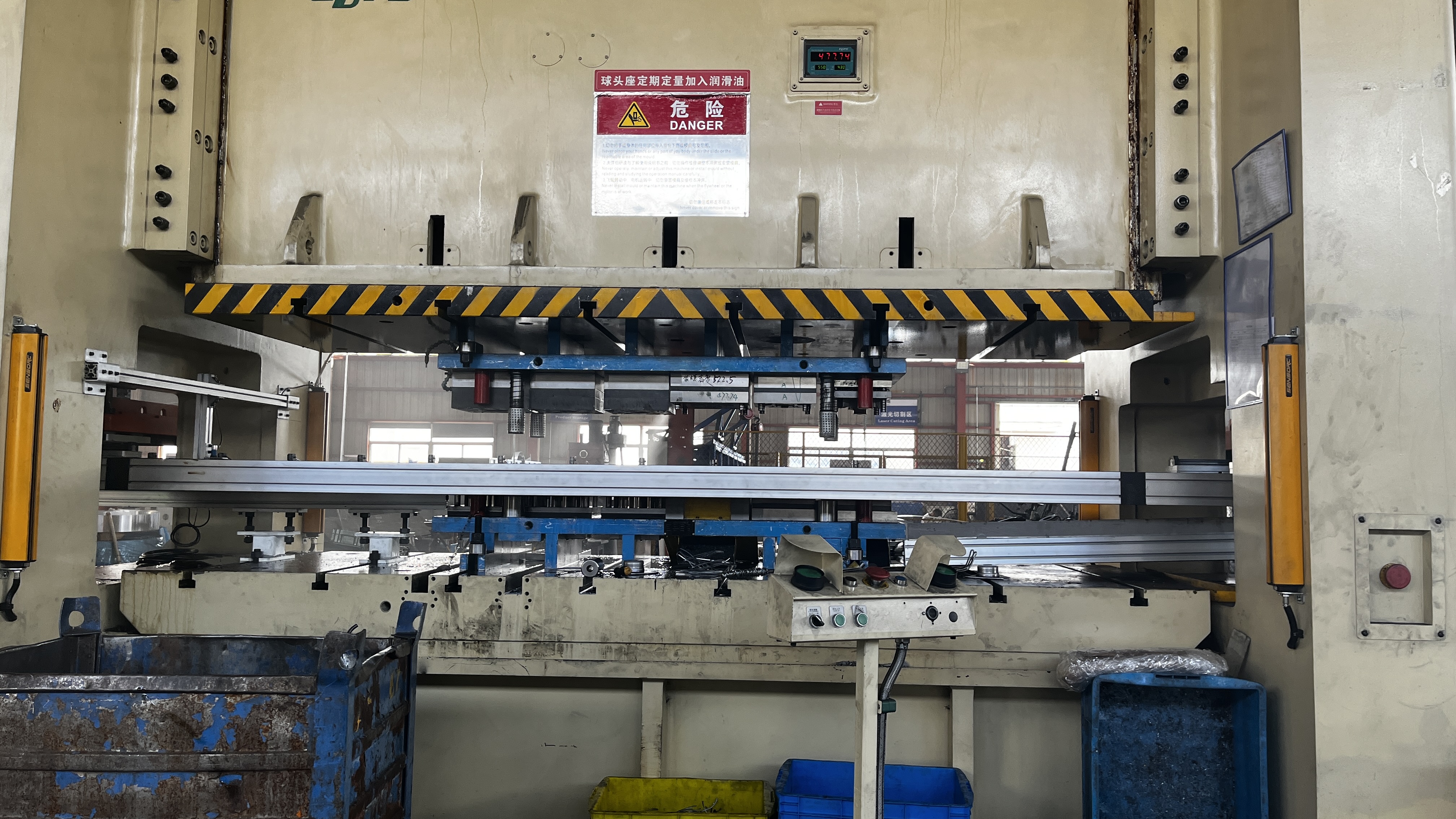
How a Die-Stamping Machine Uses Press Force
Imagine a powerful machine converting rotational energy into a downward force: that’s the core of a die-stamping machine. The press—be it mechanical, hydraulic, or servo-driven—delivers force through a ram, which moves the punch into the die set. This action cuts or forms the metal sheet, producing high volumes of identical parts with tight tolerances. The interplay between forming die design and press capability is what makes modern manufacturing so efficient and precise.
Why Tool and Die Terminology Matters
Sounds complex? It can be, but understanding the right terms helps you communicate clearly with engineers, suppliers, and operators. Knowing the difference between a die button and a die shoe, or between a stripper and a guide pin, reduces errors and speeds up troubleshooting. Mastering tool and die meaning is the first step to better design, safer operation, and higher-quality results in die for manufacturing settings.
Key Takeaway: Precision in die alignment—using quality guide pins and bushings—directly influences edge quality, part consistency, and the lifespan of your die set.
Safety and Alignment Basics
Before you power up any press and die system, safety is paramount. Always check for proper guarding, ensure all guide pins and bushings are free of wear, and confirm the die is correctly aligned in the press. Even a small misalignment can cause premature wear or part defects. For more on safety and alignment, manufacturer manuals and industry associations like the Precision Metalforming Association offer detailed guidelines and training resources.
Now that you have a solid foundation, the next chapter will guide you through selecting the right die type for your part—from simple single-hit dies to advanced progressive systems.
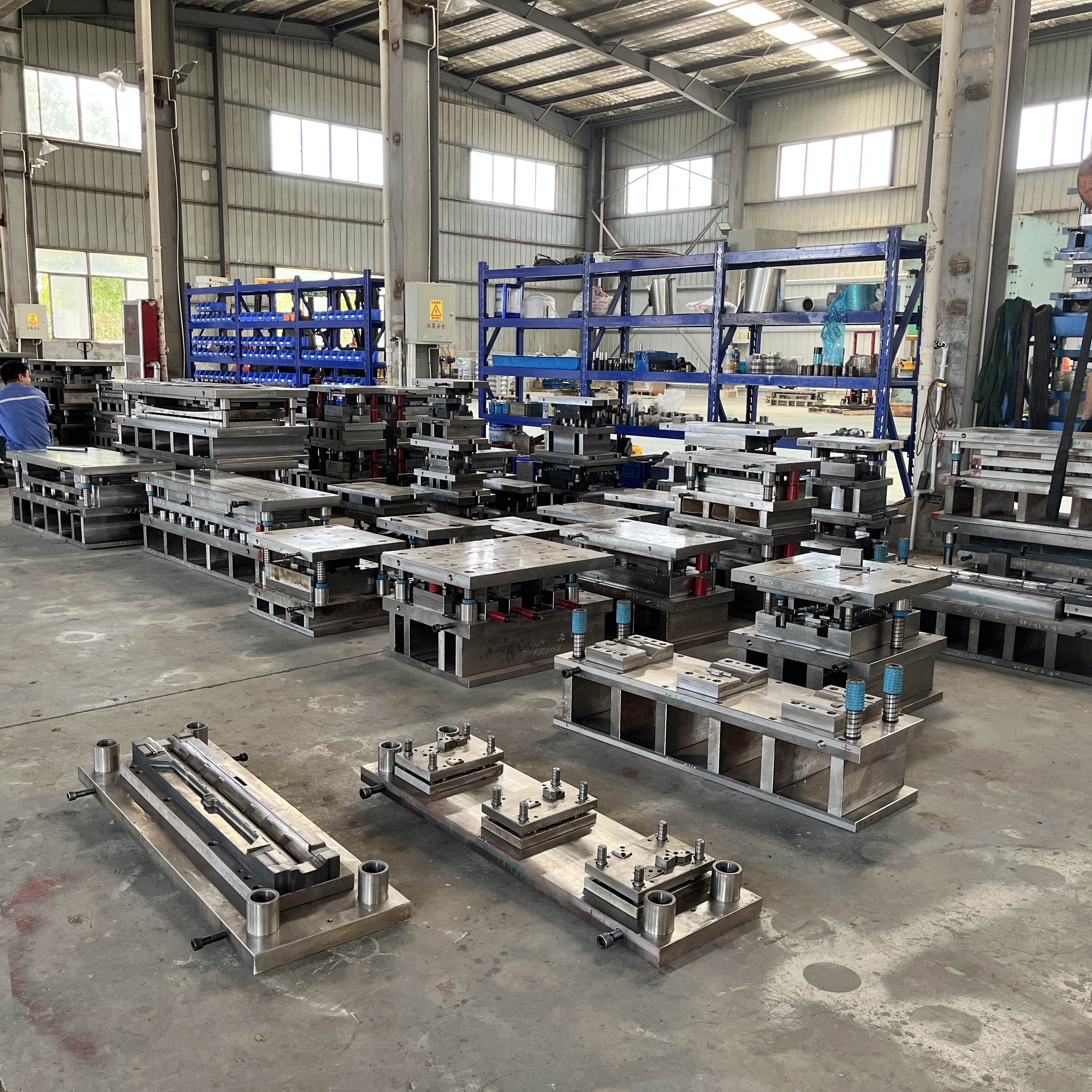
Choosing The Right Die Type For Your Part
When you’re faced with a new part design, one of the first questions to ask is: which stamping die best fits your geometry, tolerance, and production needs? The answer can dramatically impact your cost, lead time, and even your product’s quality. Let’s break down the main types of stamping dies—single-hit, compound, progressive, and transfer—so you can make an informed decision for your next project.
Single-Hit And Compound Dies: When Simplicity Wins
Imagine you need a simple, flat washer or bracket. In these cases, compound die stamping or single-hit dies are often your best bet. These dies perform one or more operations—like blanking or piercing—in a single press stroke. They’re cost-effective for lower volumes or straightforward geometries, and they keep setup and maintenance simple. However, they’re not ideal for parts with multiple bends or intricate features.
Progressive Die Metal Stamping For High Volumes
If your part requires multiple forming steps—think tabs, holes, and bends all in sequence—progressive die metal stamping is the go-to. Here, the strip of metal advances through a series of stations, with each station performing a different operation. This enables high-speed production of complex parts with tight tolerances. Although the initial tooling cost is higher, the per-part cost drops dramatically as volumes rise. Progressive metal stamping dies are common in automotive, electronics, and appliance industries.
Transfer Dies For Large Or Complex Forms
What if your part is large, deep-drawn, or has features that can’t be formed in a single strip? That’s where transfer dies shine. In this die stamping process, the part is mechanically moved from station to station—outside the strip—allowing for more complex shapes and larger sizes. While setup and tooling are more involved, transfer dies offer unmatched flexibility for intricate, multi-step forming dies.
How Station Count Affects Cost And Lead Time
The number of stations in your stamping dies—whether progressive or transfer—directly influences both tooling complexity and cost. More stations mean more operations per cycle but also higher upfront investment and longer tryout times. Maintenance needs also rise as complexity increases, so factor in long-term support when planning your project.
| Die Type | Typical Part Complexity | Setup Time | Changeover Flexibility | Cost Drivers | Maintenance Intensity | Tryout Complexity |
|---|---|---|---|---|---|---|
| Single-Hit/Compound | Simple, flat shapes | Short | High | Low tooling, low scrap | Low | Low |
| Progressive | Moderate to high; multi-feature | Moderate | Medium | High tooling, low per-part | Medium-High | Medium |
| Transfer | Large, deep-drawn, or intricate | Long | Low | Highest tooling, versatile | High | High |
Decision Tip: If your application calls for high volume and moderate complexity, progressive dies are usually most efficient. For large, deep, or unusually shaped parts, transfer dies often provide the best results—even if setup is more involved.
Understanding your options in stamping die selection is key to balancing cost, quality, and speed. Next, we’ll tackle how to size your press and estimate the tonnage you’ll need for safe, reliable operation.
Sizing Your Press And Estimating Tonnage Safely
When you’re preparing to run a new sheet metal die, one of the most critical steps is ensuring your press can deliver the right force—without risking tool or machine damage. Underestimating tonnage can stall production or even break equipment, while oversizing the press leads to unnecessary costs and inefficiencies. So, how do you get it right? Let’s break down the process, step by step, so you can confidently select the right die press for your application.
Key Variables For Tonnage And Energy
Imagine you’re about to specify a sheet metal die press. What numbers do you need? The answer depends on the operations your die will perform—blanking, piercing, bending, or deep drawing. For each, the fundamental variables include:
- Material thickness (t): The gauge of your sheet metal.
- Material strength: Shear strength for cutting, tensile strength for forming.
- Perimeter or length of cut (P): The total distance the punch travels through the material.
- Bend length and draw depth: For forming operations, these define how much metal is being shaped.
- Press stroke and shut height: The distance the ram travels and the minimum closed height of the die assembly.
Gather these values from your part print, material datasheet, and die design. Accurate data here is the foundation for reliable press sizing.
Cutting Versus Forming Loads
When you’re calculating tonnage, it’s crucial to distinguish between cutting (blanking, piercing) and forming (bending, drawing) loads. Each has its own formula and drivers:
- Cutting Load: Tonnage = P × t × Shear Strength (ꚍ). Here, P is the cut perimeter, t is material thickness, and ꚍ is the shear strength (often estimated as ~60% of the material’s tensile strength). This is your baseline for blanking or piercing operations. (AHSS Insights)
- Forming Load: For bending and drawing, use the part’s bend length or draw perimeter, material thickness, and tensile strength. The force required can change dramatically with material type—advanced high-strength steels (AHSS) may double or triple the tonnage needed compared to mild steel.
Remember, forming energy (the ability to deliver force over a distance) is just as important as peak tonnage—especially for deep draws or embossing. Mechanical presses only deliver full tonnage at the bottom of the stroke, while hydraulic presses can maintain it throughout.
Press Selection: Frame, Stroke, Shut Height
Once you’ve estimated your loads, match them to the press dies and the capabilities of your die for press. Consider these factors:
- Frame type: C-frame, straight-side, or four-post—each affects rigidity and access.
- Stroke length and shut height: Ensure your die set fits and operates within the press’s range.
- Press plate and bolster capacity: The press plate must support the die’s footprint and weight.
- Energy curve: For mechanical presses, check if energy is sufficient at your planned stroke rate, not just peak tonnage.
Review the press manufacturer’s capability charts and compare your estimated loads at the correct point in the stroke. For complex parts, simulation or physical tryouts may be needed to confirm real-world requirements.
Adding Safety Margins The Conservative Way
It’s tempting to size your press die punch exactly to your calculated load, but real-world variability demands a margin. Material inconsistencies, tool wear, and operational surprises can all increase force requirements. A conservative safety factor—often 20% or more—helps protect both your die and your die stamping machine. This margin is especially important for AHSS and other advanced materials, where small miscalculations can have big consequences.
- Calculate cutting and forming loads using material and geometry data.
- Add a safety margin (typically 20% or higher).
- Check the press’s tonnage and energy curves at the planned stroke and shut height.
- Verify the press plate and bolster can support the die’s size and weight.
- Confirm off-center loading does not exceed press frame limitations.
Remember: Always verify off-center loading and deflection limits per your press specifications. Even a well-sized press can be damaged if loads are not centered or if the die set deflects excessively.
Getting press sizing right is a blend of calculation, experience, and careful review of both die and machine specs. For more advanced materials or complex geometries, simulation tools and real-world tryouts offer extra confidence. Next, we’ll dive into how material choice and clearance planning set the stage for robust, repeatable results in your sheet metal die projects.
Material And Clearance Planning Frameworks
Ever tried to punch a hole in sheet metal and ended up with ragged edges or a warped part? That’s often the result of not planning clearances and features for your material. Whether you’re specifying a new sheet metal punch and die set or reviewing a drawing for production, understanding how to set clearances, bend radii, and minimum feature sizes is essential for quality and tool longevity. Let’s break down practical frameworks to help you get it right every time.
Blanking And Punching Clearance Framework
Clearance—the gap between the metal die punch and die—directly affects cut quality, burr formation, and die life. Too little clearance causes excessive wear or cracking; too much leads to large burrs and poor part accuracy. According to industry guidelines, clearance is typically set as a percentage of material thickness, with the exact value depending on the material’s hardness and ductility.
| Material | Thickness Range | Recommended Clearance Approach | Notes on Burr/Wear |
|---|---|---|---|
| Steel | 0.5–3 mm | 5–10% of thickness | Lower (5%) for precision; higher (8–10%) for longer die life |
| Stainless Steel | 0.5–2 mm | 8–10% of thickness | Higher clearance reduces risk of cracking and die wear |
| Aluminum/Brass | 0.5–3 mm | 5–8% of thickness | Softer alloys allow for tighter clearances; monitor for burring |
Use these frameworks as a starting point, then confirm with your sheet metal punch and die supplier or by referencing authoritative tables from your die set manufacturer.
Bend Radii And Minimum Features
Bend radii and hole/edge spacing are critical for avoiding cracks, tears, or distortion—especially when using a die cutter for metal. The right bend radius often depends on material ductility and thickness. Here’s a general guideline, adapted from best practices (Five Flute):
| Material | Recommended Min. Bend Radius | Min. Hole Diameter | Min. Hole-to-Edge | Notes |
|---|---|---|---|---|
| Steel (mild) | ≥ thickness | ≥ thickness | 1.5 × thickness | Increase for high-strength grades |
| Aluminum (6061-T6) | ≥ 1.5–2.5 × thickness | ≥ thickness | 1.5 × thickness | Less ductile; larger radii prevent cracking |
| Stainless Steel | ≥ 2 × thickness | ≥ thickness | 1.5–2 × thickness | Harder alloys need larger radii |
For sheet metal punch dies, avoid hole diameters smaller than the material thickness, and keep holes at least 1.5 times the thickness from the part edge to minimize distortion.
Data Sources And How To Vet Them
Where do you find the right numbers for your sheet metal punch and die set? Start with material datasheets, die supplier recommendations, and industry standards (such as those from NAAMS or the Precision Metalforming Association). Always verify data against your actual application—different alloys or tempers may require adjustments. When in doubt, request sample runs or first article inspections to confirm edge quality and part fit.
Anticipating Tool Wear With Different Alloys
Not all metal punches and dies wear the same. Harder materials like stainless steel or advanced high-strength steel accelerate tool wear and may require higher clearances or premium die coatings (AHSS Insights). Softer alloys allow for tighter fits but can still cause galling if lubrication or surface finish isn’t optimized. Regularly review tool condition and adjust clearances as needed to maximize die life and minimize downtime.
- Define edge quality and burr tolerance on drawings
- Specify deburring requirements if needed
- Standardize minimum hole diameter and spacing rules
- Note grain direction for critical bends
- Document coating thickness if parts are plated or painted
Key Takeaway: Planning clearances, bend radii, and feature spacing based on material and process data is the foundation for robust, repeatable results—whether you’re using a turret punch, progressive die, or any modern die cutter for metal applications.
With these frameworks in hand, you’re ready to specify features that balance quality, cost, and tool life. Next, we’ll dive into selecting tool steels, heat treatments, and coatings that keep your dies running longer and more reliably.
Tool Steel Heat Treat And Coatings Made Practical
When you’re choosing a sheet metal die for your next project, have you ever wondered why some tools last for millions of cycles while others wear out after just a few runs? The answer often lies in the selection of die material, heat treatment, and surface coatings. Let’s break down how these choices impact cost, tool life, and maintenance for steel stamping dies and metal forming dies—so you can make decisions with confidence.
Choosing Die Material For Life And Cost
Die material selection is a balancing act between toughness, hardness, and grindability. The most common tool steels for die plate, punches, and inserts each bring unique strengths. Here’s a quick look at popular options, based on industry-standard data:
- D2 Tool Steel: High wear resistance, excellent for long runs and abrasive materials. Slightly tougher to grind and machine, but ideal for high-volume, high-precision parts.
- A2 Tool Steel: Good all-around performance. Balances wear resistance, toughness, and size stability—great for medium production volumes.
- O1 Tool Steel: Easy to machine and heat treat; suitable for short runs or prototype dies where cost is a priority over maximum life.
- H13 Tool Steel: Used for hot work dies, but also valuable in some cold stamping where shock resistance is needed.
When selecting for a standard die, consider the material you’re stamping, expected part volume, and the complexity of your die shoe design. For example, D2 is often chosen for high-strength steels or abrasive applications, while O1 might be preferred for short-run or maintenance dies.
Heat Treatment Targets And Wear Modes
Proper heat treatment is what transforms tool steel from a soft, machinable state into a hard, wear-resistant die component. Each grade has its own ideal hardening and tempering range. For instance, D2 tool steel is typically hardened between 1800–1875°F and tempered to achieve Rockwell C 54–61, while A2 is hardened at 1700–1800°F and tempered to RC 57–62.
Common wear modes in sheet metal dies include:
- Abrasion: Repeated sliding contact with the workpiece, especially in blanking or piercing operations.
- Chipping: Brittle fracture at the cutting edge, often from improper heat treatment or excessive hardness.
- Galling: Adhesive wear, usually when forming aluminum or stainless steel without lubrication or proper surface finish.
Matching heat treatment to your die material and application is critical for maximizing tool life and minimizing downtime—even for a standard die in routine production.
Coatings And Surface Treatments
When your die needs extra protection against wear, friction, or chemical attack, surface engineering steps in. Modern coatings—like PVD (Physical Vapor Deposition) or CVD (Chemical Vapor Deposition) films—can dramatically extend the life of your die plate or punch. According to surface engineering experts, coatings such as TiN, TiCN, or CrN reduce friction, resist oxidation, and minimize galling, especially in demanding metal forming dies applications.
Pros and Cons of Common Coatings
-
TiN (Titanium Nitride):
Pros: Excellent wear resistance, reduces friction, widely available.
Cons: Moderate oxidation resistance, not ideal for high-temperature forming. -
CrN (Chromium Nitride):
Pros: Superior corrosion and oxidation resistance, good for aluminum or stainless forming.
Cons: More expensive, application process may be more complex. -
PVD/CVD Hard Coatings:
Pros: Customizable for specific wear or chemical environments.
Cons: May require specialized cleaning and handling to avoid damaging thin films.
For most steel stamping dies, a combination of the right tool steel, optimal heat treatment, and a well-chosen coating delivers the best balance of cost and performance.
Linking Material Choice To Maintenance Strategy
Imagine your die is running 24/7 in a high-volume line. Your maintenance plan, from regrinding to recoating, should match your material and coating strategy. Tougher steels like D2 may go longer between sharpenings but require more effort to grind. Softer grades like O1 are easier to service but wear faster. Coatings can reduce the frequency of maintenance, but only if the underlying substrate is properly heat treated and supported.
| Component | Common Material | Typical Hardness (Rc) | Finishing/Coating | Notes |
|---|---|---|---|---|
| Punch | D2, A2, M2 | 54–62 | TiN, TiCN, CrN | Choose based on part material and wear mode |
| Die Button | D2, A2 | 54–62 | TiN, CrN | High wear areas benefit from premium coatings |
| Stripper | A2, O1 | 50–60 | Optional (TiN, CrN) | Surface finish impacts part ejection |
| Pilot | S7, D2 | 54–58 | None or TiN | Shock resistance is key for pilots |
By matching your die material, heat treatment, and coatings to your expected production and maintenance capabilities, you’ll ensure your die shoe and all critical components deliver the performance you need—cycle after cycle. Next, we’ll show how to turn these design and material choices into an efficient workflow from strip layout to tryout.
Die Design Workflow From Strip To Tryout
Ever wondered how a sheet metal die goes from a simple drawing to a high-speed production tool that churns out flawless parts every minute? The secret lies in a disciplined, step-by-step workflow that bridges theory and real-world manufacturing. Let’s break down the essentials of die design—from the first strip layout to the final tryout—so your tooling dies deliver both quality and reliability.
Strip Layout And Station Sequencing
Imagine planning a road trip: you wouldn’t start driving without a map. The same goes for sheet metal die design. The strip layout is your roadmap, showing how raw material progresses through each station of the die. According to industry best practices, this step determines material usage, station count, and the sequence of operations—piercing, bending, forming, and trimming. Good strip layouts optimize scrap, ensure part stability, and set the stage for a robust die assembly.
- Part Print Review: Analyze the part’s geometry, tolerances, and material properties. Is it suitable for stamping? Are there deep draws or tight corners that need special attention?
- Formability Assessment: Check for features that may cause cracks, wrinkles, or springback. Adjust the part design or sequence if needed.
- Strip Layout Planning: Map out how the part will be formed step by step. Decide on carrier design and scrap management.
- Station Sequencing: Define each operation’s order—pierce, bend, form, trim—for optimal material flow and die stability.
- Detail Die Design: Model punches, dies, pilots, lifters, and strippers. Set clearances and radii based on material guidelines.
- Simulation & Validation: Use CAE tools (if available) to predict material flow and spot potential issues before building the die.
- Tolerancing: Specify critical dimensions, fits, and GD&T callouts for all die assembly components.
- Manufacturing Drawings: Create detailed 2D/3D drawings for each component and assembly.
- Build & Tryout: Manufacture the die, assemble it, and conduct initial runs. Tweak as needed for part quality and process stability.
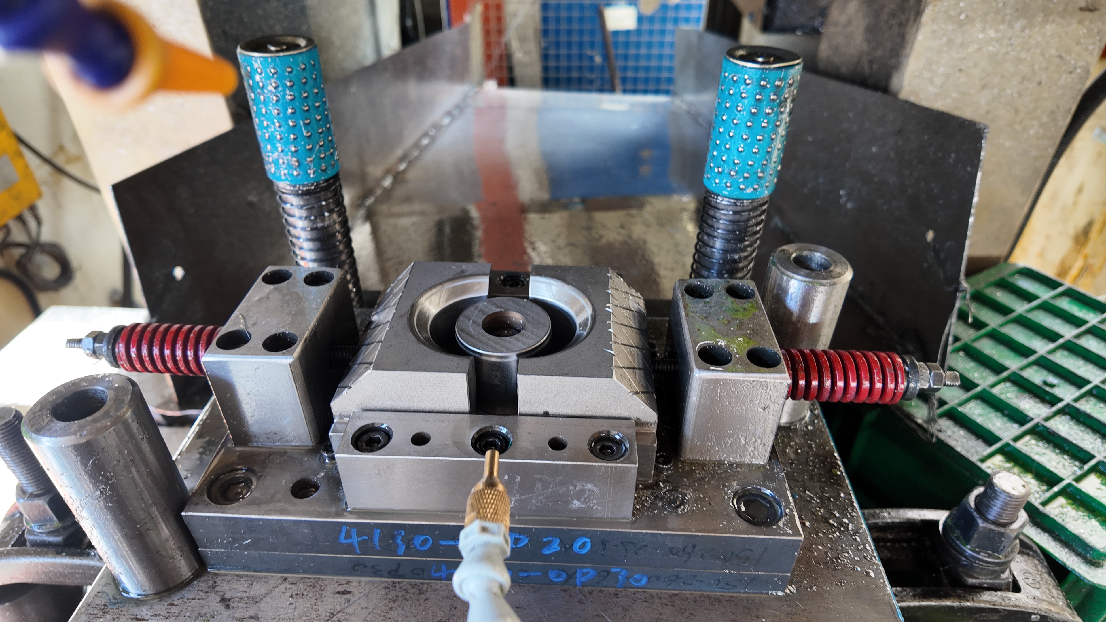
Pilots, Lifters, Strippers, And Knockout Strategy
When you look inside a stamping die design, you’ll see more than just punches and cavities. Pilots ensure precise strip positioning at each station. Lifters and strippers control part ejection and prevent jams. Knockouts clear finished parts and scrap, keeping the process smooth and continuous. Strategic placement and sizing of these elements are essential for robust metal stamping die design (Jeelix).
- Pilots: Engage the strip at key locations, ensuring repeatable alignment for every stroke of the die-stamping machine.
- Lifters: Raise the strip or part to the correct height for the next operation, preventing binding or misfeeds.
- Strippers: Hold the material flat and remove it from the punch after cutting or forming.
- Knockouts: Eject finished parts and scrap reliably, reducing downtime and minimizing manual intervention.
For best results, always reference validated guidelines for pilot relief, minimum web widths, and bypass notches from trusted sources or standards.
Sensoring And Mistake-Proofing
Modern tooling dies aren’t just mechanical—they’re smart. Sensors can detect misfeeds, part-out conditions, and even monitor tonnage in real time. Embedding sensors in critical locations within the die helps prevent crashes, protect expensive tooling, and catch quality issues early. According to advanced die design frameworks, integrating sensor networks is now a best practice for high-speed, high-mix operations.
- Misfeed sensors stop the press if the material is out of position.
- Part-out sensors confirm finished parts are ejected before the next cycle.
- Tonnage monitors track force and catch anomalies before they cause damage.
Design For Maintainability And Quick Change
Imagine you’re running a busy shop with dozens of die changes per day. A well-designed sheet metal die design makes maintenance and changeover fast and predictable. Features like standardized components, easy-access wear parts, and modular die shoes are key. Adopting Quick Die Change (QDC) and Single-Minute Exchange of Die (SMED) principles during die assembly can slash downtime and boost overall productivity.
- Use standardized fasteners and components for faster repairs.
- Design access windows and removable plates for easy inspection and replacement.
- Plan for modular sections—replace only worn modules, not the whole die.
- Insufficient carrier rigidity can cause strip misfeeds and part defects.
- Missed pilot relief leads to alignment issues and accelerated wear.
- Poor knockout design results in jams and downtime.
- Lack of sensor integration increases the risk of catastrophic die crashes.
Key Takeaway: A disciplined workflow—starting with robust strip layout and ending with sensor-driven mistake-proofing—transforms die design from guesswork into a repeatable, high-performance process.
By following these structured steps and anticipating common pitfalls, you’ll ensure your tooling dies and die-stamping machine work together seamlessly for reliable, high-quality production. Next, we’ll explore how to build quality into every part through inspection planning and QA best practices.
Quality Planning And Inspection For Stamped Parts
When you’re producing high volumes of stamped metal parts, how do you make sure every piece meets the mark? The answer lies in a robust quality plan tailored to the sheet metal stamping process. By combining structured inspection strategies with clear documentation, you can catch problems early, reduce scrap, and deliver consistent results—whether you’re running precision die stamping or simple brackets. Let’s walk through a practical approach to quality assurance for any metal stamping die application.
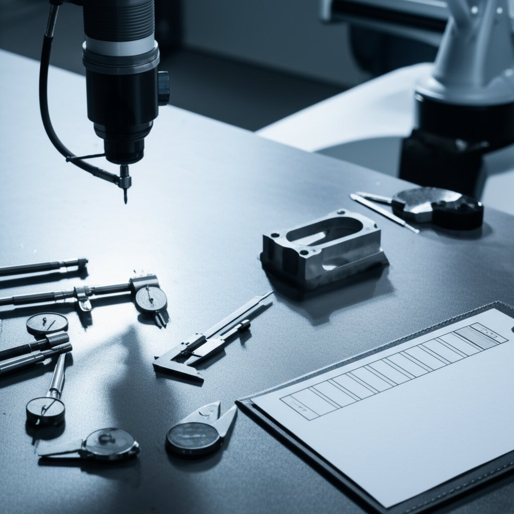
First Article Inspection: What To Measure First
First Article Inspection (FAI) is your front line of defense against costly mistakes. Think of it as a dry run: before mass production, you carefully check the first part off the metal stamping die to ensure every feature matches the drawing and spec. According to best practices, a typical FAI covers:
- Critical dimensions—hole locations, slot widths, formed angles, and trim edges
- Surface finishes and edge quality
- Material validation—certificates, hardness, or chemistry
- Tooling information—die ID, press setup, and program numbers
Measurement tools range from calipers and micrometers to CMMs (Coordinate Measuring Machines) for tight tolerances. The FAI process also includes a formal report, often with ballooned drawings and detailed notes, submitted for customer approval before full-scale production begins. This step is crucial for both OEM and ODM projects, and is often required in regulated industries.
In-Process Checks And Sampling
Once production is underway, in-process inspections keep your line running smoothly. These checks are designed to catch issues before they multiply—think of them as regular pit stops for your stamping die components. Typical in-process checks include:
- Spot-checking key dimensions on a set schedule (every X parts or every Y minutes)
- Visual inspections for burrs, cracks, or surface defects
- Verifying part alignment and feature positions using go/no-go gauges or fixture checks
The frequency and method depend on part complexity and risk. For high-precision die stamping, you may use statistical process control (SPC) to monitor trends and trigger corrective action if variation creeps in. Simpler parts might only need periodic attribute checks. The key is consistency: use the same gauges, reference the same datums, and record results clearly.
| Feature ID | Nominal | Tolerance | Gauge/Method | Frequency | Reaction Plan |
|---|---|---|---|---|---|
| Hole A | Ø5.00 mm | ±0.05 mm | CMM | First/100 pcs | Stop & investigate if OOT |
| Edge B | 10.00 mm | ±0.10 mm | Caliper | Every 30 mins | Adjust die if drift |
| Angle C | 90° | ±1° | Protractor | First/Last run | Review setup |
GD&T Callouts That Aid Function
Ever struggled with parts that technically “meet the print” but don’t fit or function in the assembly? That’s where smart use of GD&T (Geometric Dimensioning & Tolerancing) comes in. For stamped parts, focus on:
- Position callouts for holes and slots (using true position tolerances)
- Flatness and perpendicularity for mating surfaces
- Profile tolerances for complex contours
Apply GD&T from well-chosen datums that reflect how the part is used in the final assembly. This makes inspection more meaningful and helps avoid false rejects or assembly issues.
Documenting Conformance And Traceability
Imagine trying to solve a quality problem weeks after production—without clear records, it’s like searching for a needle in a haystack. Good documentation is your safety net. For every batch, keep:
- Inspection reports with results, gauge IDs, and signatures
- Material certifications and batch numbers
- Setup logs for die and press parameters
- Photos and notes for any deviations or rework
For regulated industries or critical applications, align with standards like PPAP (Production Part Approval Process) or AS9102 for aerospace. Digital records make it easier to track trends, support audits, and maintain customer trust.
Key Insight: Consistent datum use across prints, FAI/PPAP, and in-process checks dramatically reduces debate and rework—making your metal stamping die projects smoother and more predictable.
First Article Signoff Steps (Sample Text-Only Template)
- Review and approve FAI report with all measurement results
- Confirm material and finish certifications are attached
- Sign off by QC, engineering, and customer (if required)
- Release for full production only after documented approval
In-Process Audit Checklist (Sample)
- Verify gauges/calibration before use
- Check critical features per inspection plan
- Record results and sign off for each shift
- Escalate any out-of-tolerance findings immediately
With these strategies, you’ll build quality into every step of your sheet metal stamping process. Up next, we’ll explore how to select the right partners and technologies to further reduce risk and optimize your stamping operations.

Comparing Automotive Stamping Die Partners
When you’re sourcing automotive stamping dies for your next project, it’s easy to get overwhelmed by technical jargon and marketing claims. How do you sift through stamping die manufacturers and find a partner that truly reduces risk, controls costs, and delivers consistent quality? Let’s break down the key decision factors—CAE simulation, engineering collaboration, and certification—so you can confidently evaluate your options for custom metal stamping dies.
Why CAE Simulation Reduces Tryout Iterations
Ever had a new die arrive, only to discover wrinkles or cracks during the first tryout? That’s where advanced CAE (Computer-Aided Engineering) simulation makes a difference. By virtually modeling the stamping process, top metal stamping die manufacturers can predict forming defects, optimize material flow, and even estimate minimum press force before a single tool is cut. This digital approach slashes costly physical tryouts and shortens debug cycles, especially for complex automotive panels and high-strength materials. According to industry case studies, simulation helps prevent springback, thinning, and cosmetic issues—so your parts meet tight specs the first time (Keysight).
Engineering Collaboration And DFM Depth
Imagine launching a new part with zero surprises. That’s the goal of strong engineering collaboration and deep DFM (Design for Manufacturability) reviews. Leading stamping die manufacturers work side-by-side with your team from day one, reviewing every feature for formability, tolerance, and process risk. Early engagement means potential issues—like tight radii, complex draw depths, or ambiguous tolerances—are flagged and resolved before tooling begins. This not only de-risks launches but also streamlines communication and change management throughout the project lifecycle.
Certification And Process Control Signals
How do you know a supplier’s quality claims are real? Certifications like IATF 16949 or ISO 9001:2015 signal robust process controls, traceability, and a culture of continuous improvement. For automotive projects, IATF 16949 is often non-negotiable. Look for partners with a low parts-per-million (PPM) defect rate and a reputation for on-time delivery—these are strong indicators of operational discipline and supply chain reliability. A safe, stable workplace and a well-trained workforce also support long-term value and fewer disruptions.
| Partner | CAE Simulation | DFM/Engineering Depth | Certification | Prototyping Speed | Global Experience | Post-Launch Support |
|---|---|---|---|---|---|---|
| Automotive Stamping Dies | Advanced (full die/process simulation) | High (in-depth reviews, formability analysis) | IATF 16949 | Rapid (prototyping to mass production) | Global (trusted by 30+ brands) | Comprehensive (engineering, process, QA) |
| Talan Products | Available (focus on process control) | Strong (training, continuous improvement) | ISO 9001:2015 | Efficient (high-volume capability) | Long-term US/Global clients | Proven (quality, delivery, training) |
| Hatch Stamping | In-house engineering software | Hands-on (custom solutions, CMM validation) | ISO 14001/IATF 16949 | Flexible (engineering changes supported) | 70+ years, multi-industry | Repair, engineering changes, ongoing QC |
Key Takeaway: Prioritize partners with advanced CAE, deep DFM engagement, and automotive-grade certification. These capabilities directly reduce tryout loops, minimize defects, and ensure your custom metal stamping die project runs smoothly from concept to launch.
Choosing the right partner isn’t just about price or capacity—it’s about finding a team that brings simulation-driven insight, collaborative engineering, and proven quality systems to every custom metal stamping dies project. Next, we’ll show you how to turn your stamped part concept into a production-ready RFQ with actionable steps and resource suggestions.
Next Steps And Resources For Better Outcomes
Ready to turn your sheet metal die concept into a finished part that meets every requirement? Whether you’re new to custom sheet metal stamping or looking to refine your approach, a clear, step-by-step process is your best friend. Let’s walk through the essential actions to move smoothly from initial idea to production launch—minimizing surprises and setting your project up for success.
From Concept To RFQ: What To Prepare
Imagine you’re submitting a request for quote (RFQ) for a new part. What details will help your supplier deliver an accurate, fast quote—and a part that works right the first time? According to industry best practices, you should gather:
- Part print or CAD model: Include all relevant views, dimensions, and critical features.
- Material specification: Clearly state alloy, temper, and thickness. Reference standards if possible.
- Expected volume: Estimate yearly or lot quantities—this impacts die selection and cost.
- Tolerance priorities: Highlight critical-to-function features and realistic tolerances (avoid over-tolerancing).
- Finishing requirements: Specify coatings, painting, or deburring needs.
- Inspection plan draft: List key dimensions to check and preferred methods (e.g., CMM, gauge).
- Maintenance expectations: Indicate if you require spare parts, die maintenance plans, or specific documentation.
By preparing these details up front, you’ll streamline communication and enable faster, more accurate quoting—key for both tool and die manufacturing and custom sheet metal stamping projects.
Design Review And Simulation Checkpoints
Before you green-light tooling, pause for a thorough design review. This is where you catch problems before they become costly. Consider these checkpoints:
- Are all features manufacturable with the chosen process?
- Have you validated material formability for bends, draws, or embosses?
- Is GD&T applied to functional datums that reflect assembly needs?
- Do you have simulation results (if available) to predict risks like wrinkling, cracking, or excessive springback?
For complex or high-volume jobs, leveraging CAE (Computer-Aided Engineering) simulation can save time and reduce tryout cycles. If your resources are limited, consider working with an experienced partner who offers design-for-manufacturing (DFM) reviews and simulation as part of their package. For example, Automotive Stamping Dies by Shaoyi Metal Technology provides CAE-backed feasibility checks and collaborative engineering support—one of several strong options in the current market.
Launch Readiness And Maintenance Planning
Imagine you’re at the finish line: tooling is built, first articles are approved, and production is set to begin. What keeps your project on track from here? Launch readiness means:
- Finalizing all inspection documents and quality signoffs
- Confirming operator training and process documentation
- Establishing a spare parts and maintenance schedule for your die
- Documenting lessons learned for future die manufacturing projects
Building these steps into your workflow ensures that your investment in tool and die manufacturing pays off over the long term—reducing downtime, scrap, and costly rework.
Key Insight: Early clarity on datums, clearances, and quality requirements is the single best way to avoid late-stage changes and delays in custom sheet metal stamping projects.
No matter your experience level, following a structured approach from concept to launch will help you get the most out of your sheet metal die investment. And when you need extra expertise—whether for DFM reviews, simulation, or advanced process control—don’t hesitate to consult with proven partners, including those offering CAE-led workflows and automotive-grade certification. The right support can make all the difference between a smooth launch and a costly do-over.
Frequently Asked Questions About Sheet Metal Dies
1. What is a sheet metal die and how does it work?
A sheet metal die is a precision tool used with a press to cut or form metal sheets into specific shapes. It consists of components like punches, die buttons, and guide pins that work together to shape metal with high repeatability. The die is mounted in a press, which applies force to the punch, pushing the material into the die cavity to create the desired part geometry.
2. Why is tool and die terminology important in manufacturing?
Understanding tool and die terminology ensures clear communication between engineers, operators, and suppliers. It helps avoid costly errors, speeds up troubleshooting, and ensures that everyone involved in the manufacturing process is aligned on requirements and expectations, leading to higher quality and safer operations.
3. How do I choose the right die type for my stamped part?
Selecting the right die depends on your part's complexity, production volume, and tolerance needs. Single-hit or compound dies suit simple, low-volume parts. Progressive dies are ideal for high-volume, multi-feature parts, while transfer dies handle large or complex geometries. Assessing station count, changeover flexibility, and maintenance intensity will help match the die type to your project.
4. What factors should I consider when sizing a press for my sheet metal die?
Key factors include the material type and thickness, total cut perimeter, forming or cutting force required, and the press's stroke and shut height. Adding a safety margin to your calculated tonnage is essential for reliable operation. Always confirm the press plate and bolster can handle the die's size and weight, and check for off-center loading limits.
5. How can I ensure quality and consistency in stamped metal parts?
Implementing a robust quality plan is crucial. Start with first article inspections to verify dimensions and features, then use in-process checks and standardized gauges for ongoing monitoring. Apply GD&T callouts for functional features and maintain thorough documentation for traceability. Partnering with certified suppliers and leveraging CAE simulation can further reduce defects and enhance consistency.