 Small batches, high standards. Our rapid prototyping service makes validation faster and easier —

Stamping High Strength Steel Challenges: Engineering Solutions for Wear & Springback
TL;DR
Stamping high strength steel presents three primary engineering hurdles: severe springback due to high yield strength, rapid tool wear from extreme contact pressures, and dangerous reverse tonnage (snap-through) that can damage press internals. Overcoming these challenges requires a shift from traditional mild steel practices to advanced mitigation strategies, including stress-based simulation for compensation, the use of Powder Metallurgy (PM) tool steels with specialized coatings, and servo press technology to manage energy at lower speeds. Successful fabrication depends on optimizing the entire process—from die design to lubrication—to maintain dimensional accuracy without sacrificing equipment life.
Challenge 1: Springback and Dimensional Control
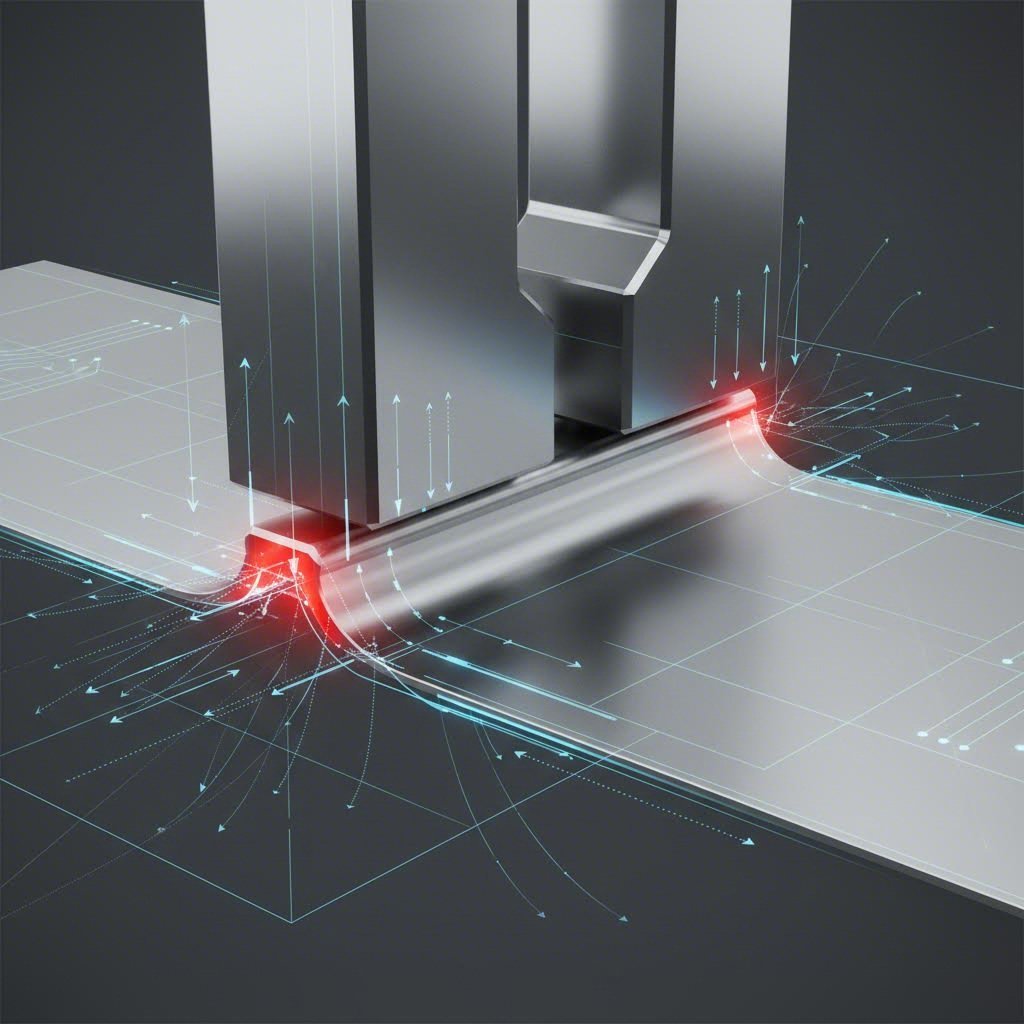
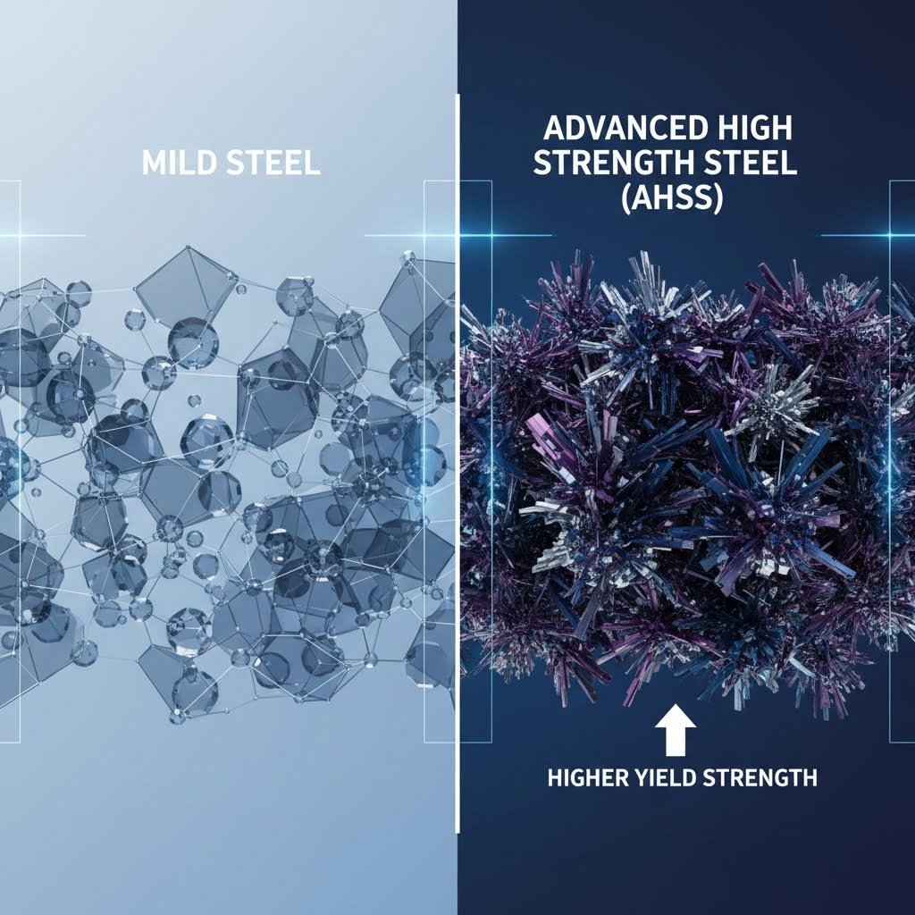
The most pervasive issue in stamping high strength steel (AHSS) and high-strength low-alloy (HSLA) materials is springback—the elastic recovery of the metal after forming load is removed. Unlike mild steel, which retains its shape relatively well, AHSS has a significantly higher yield strength, causing it to “bounce back” aggressively. This geometric deviation is not just a linear return; it often manifests as sidewall curl and twist, making dimensional control notoriously difficult for precision components.
Traditional trial-and-error methods are inefficient for AHSS. Instead, engineers must rely on advanced finite element analysis (FEA) that utilizes stress-based prediction models rather than simple strain-based criteria. Simulation allows die designers to apply geometric compensation—deliberately over-bending or distorting the die face so the part springs back into the correct net shape. However, simulation alone is often insufficient without mechanical intervention.
Practical process adjustments are equally critical. Techniques such as rotary bending and the use of lock steps or “coin beads” can help lock stresses into the material. According to The Fabricator, utilizing servo press technology to program a “dwell” at the bottom of the stroke allows the material to relax under load, significantly reducing elastic recovery. This “setting the shape” approach is far more effective than simple crash forming, which requires excessive tonnage and accelerates tool wear.
Challenge 2: Tool Wear and Die Failure
The elevated yield strengths of AHSS materials—often exceeding 600 MPa or even 1000 MPa—exert tremendous contact pressure on stamping tooling. This environment creates a high risk of galling, chipping, and catastrophic tool failure. Standard tool steels like D2 or M2, which perform adequately for mild steel, often fail prematurely when processing AHSS due to the material's abrasive nature and the high energy required to form it.
To combat this, manufacturers must upgrade to Powder Metallurgy (PM) tool steels. Grades such as PM-M4 offer superior wear resistance for high-volume runs, while PM-3V provides the toughness needed to prevent chipping in high-impact applications. Beyond material selection, surface preparation is vital. Wilson Tool recommends switching from a cylindrical grind to a straight-line grind on punches. This longitudinal texture reduces stripping friction and minimizes the risk of galling during the retraction phase.
Surface coatings are the final line of defense. Advanced Physical Vapor Deposition (PVD) and Thermal Diffusion (TD) coatings, such as Titanium Carbonitride (TiCN) or Vanadium Carbide (VC), can extend tool life by up to 700% compared to uncoated tools. These coatings provide a hard, lubricious barrier that withstands the extreme heat generated by the deformation energy of high strength steel.
Challenge 3: Press Capacity and Snap-Through Loads
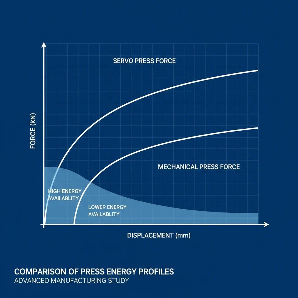
A hidden danger in stamping high strength steel is the impact on the press itself, specifically regarding energy capacity and reverse tonnage (snap-through). Mechanical presses are rated for tonnage near the bottom of the stroke, but forming AHSS requires high energy much earlier in the stroke. Furthermore, when the material fractures (breaks through), the sudden release of stored potential energy sends a shockwave back through the press structure. This “snap-through” load can destroy bearings, connecting rods, and even the press frame if it exceeds the equipment's rated reverse tonnage capacity (typically only 10-20% of forward capacity).
Mitigating these forces requires careful equipment selection and die engineering. Staggering punch lengths and applying shear angles to cutting edges can distribute the breakthrough load over time, reducing the peak shock. However, for heavy-duty structural components, the press capability itself is often the bottleneck. Partnering with a specialized manufacturer is often necessary to handle these loads safely. For instance, Shaoyi Metal Technology’s comprehensive stamping solutions include press capabilities up to 600 tons, allowing for the stable production of heavy-gauge automotive components like control arms and subframes that would overwhelm smaller standard presses.
Energy management is another critical factor. Slowing down a conventional mechanical press to reduce shock loads inadvertently reduces the available flywheel energy (which is proportional to the square of velocity), leading to stalling. Servo presses solve this by maintaining full energy availability even at low speeds, allowing for a slow, controlled breakthrough that protects both the die and the press drivetrain.
Challenge 4: Formability Limits and Edge Cracking
As steel strength increases, ductility decreases. This trade-off manifests as edge cracking, particularly during flanging or hole-expansion operations. The microstructural phases that give AHSS its strength (such as martensite) can act as crack initiation sites when the material is sheared. A standard cutting clearance of 10% of material thickness, common for mild steel, often results in poor edge quality and subsequent failure during forming.
Optimizing die clearance is the primary countermeasure. According to MetalForming Magazine, austenitic stainless grades may require clearances as high as 35-40% of material thickness, while ferritic and dual-phase steels typically require 10-15% or optimized “engineered clearances” to minimize the work-hardened zone at the shear edge. Laser trimming is an alternative for prototyping, but for mass production, engineers often use a shaving operation—a secondary cut that removes the work-hardened edge material before the final forming step—to restore edge ductility and prevent cracking.
Conclusion
Successfully stamping high strength steel is not merely about applying more force; it requires a fundamental re-engineering of the fabrication process. From adopting simulation-driven compensation for springback to utilizing PM tool steels and high-capacity servo presses, manufacturers must treat AHSS as a distinct material class. By addressing the physics of elastic recovery, wear, and fracture mechanics proactively, fabricators can produce lighter, stronger components without incurring prohibitive scrap rates or equipment damage.
Frequently Asked Questions
1. What is the biggest challenge in stamping high strength steel?
The most significant challenge is typically springback, where the material elastically recovers its shape after the forming force is removed. This makes achieving tight dimensional tolerances difficult and requires advanced simulation and die compensation strategies to correct.
2. How do you reduce tool wear when stamping AHSS?
Tool wear is mitigated by using Powder Metallurgy (PM) tool steels (like PM-M4 or PM-3V) which offer superior toughness and wear resistance. Additionally, applying advanced coatings like PVD or TD (Thermal Diffusion) and optimizing punch grinding direction (longitudinal vs. cylindrical) are essential steps to extend tool life.
3. Why is reverse tonnage dangerous for stamping presses?
Reverse tonnage, or snap-through, occurs when the material fractures and the stored energy in the press frame is suddenly released. This shockwave creates backward force on the connection points. If this force exceeds the press's rating (usually 10-20% of forward capacity), it can cause catastrophic damage to bearings, cranks, and the press structure.