 Small batches, high standards. Our rapid prototyping service makes validation faster and easier —

Stamping Die Components, Explained: From Lateral Loads To Lifespan
Start With A Clear Map Of The Die System
When you first encounter a metal stamping die, the array of parts can seem overwhelming. Yet, understanding stamping die components is the foundation for every engineer or sourcing specialist aiming for reliable, cost-effective production. So, what exactly goes on inside a die set, and why does it matter to your next project?
What Stamping Die Components Do
At its core, a stamping die is a precision tool that transforms flat sheet metal into finished parts using a press. But it’s the individual components inside the die set that make this possible. Each element—whether it guides, cuts, forms, strips, or ejects—has a specific job to ensure the part is made accurately, cycle after cycle. Imagine a symphony: if one instrument is out of tune, the whole performance suffers. Similarly, the wrong component or poor alignment can lead to defects, downtime, or costly fixes.
The Die Press And Component Interaction
The die for press operations is more than just a collection of metal parts. The press applies force, but it’s the interaction between the press, the die set, and the chosen components that determines part quality and production efficiency. Selecting the right stamping die components impacts not only accuracy and uptime, but also the cost per part and how often maintenance is required. For example, using high-precision guide pins and bushings helps maintain alignment, while robust springs ensure consistent stripping and ejection.
Core Assemblies In A Modern Die Set
Let’s break down the essential groups of components you’ll find in most press dies and metal stamping dies:
- Guiding: Guide pins and bushings align upper and lower die shoes for repeatable accuracy.
- Cutting/Piercing: Punches and die buttons create holes or shapes by shearing the metal.
- Forming: Forming punches and die blocks bend or shape the part.
- Force: Die springs or nitrogen cylinders provide the energy needed for stripping and ejection.
- Stripping/Ejection: Strippers and ejectors remove the part from the die after forming or cutting.
- Motion/Cams: Cam units drive side actions or complex forms not possible with a simple up-and-down stroke.
- Sensing: Sensors monitor part position, die alignment, or detect misfeeds to prevent damage.
| Function | Typical Components | Failure Signals |
|---|---|---|
| Guiding/Alignment | Guide pins, bushings | Misalignment, uneven wear, scoring marks |
| Cutting/Piercing | Punches, die buttons | Burrs on parts, chipped edges, increased force needed |
| Forming | Forming punches, die blocks | Cracks, wrinkles, inconsistent bends |
| Force | Die springs, nitrogen cylinders | Incomplete stripping, weak ejection, spring breakage |
| Stripping/Ejection | Strippers, ejectors | Parts sticking in die, incomplete ejection |
| Motion/Cams | Cam units | Missed forms, jamming, timing issues |
| Sensing | Sensors, limit switches | False alarms, undetected misfeeds, unplanned stops |
Consistent component selection tied to part geometry and press capability reduces trial iterations and maintenance surprises.
By building a shared vocabulary around stamping die, die sets, and their assemblies, teams can communicate more clearly—whether they’re troubleshooting, ordering spare parts, or optimizing for uptime. As you move forward, you’ll notice that understanding these fundamentals is crucial, whether you’re comparing basic definitions or diving into advanced optimization of metal stamping die systems.
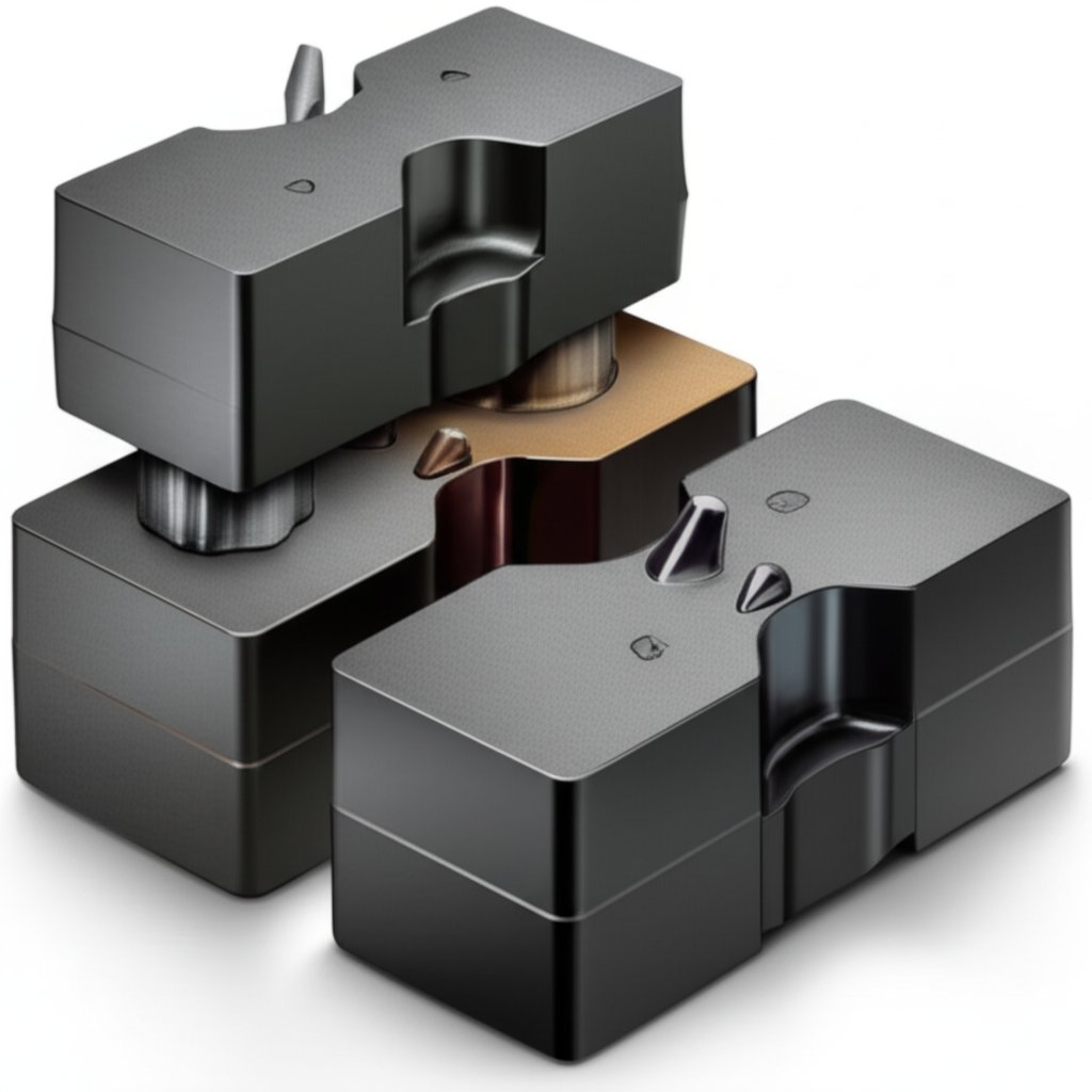
Exploded Component Relationships You Can Picture
Ever wondered how all the pieces inside a stamping die fit together so seamlessly? It’s not just about stacking metal parts—it’s a precise assembly where each component’s position and alignment directly impact your final part quality and the die’s lifespan. Let’s walk through a typical assembly, layer by layer, so you can visualize how guide pins, die shoes, and precision dowel pins come together to create a robust, serviceable tool.
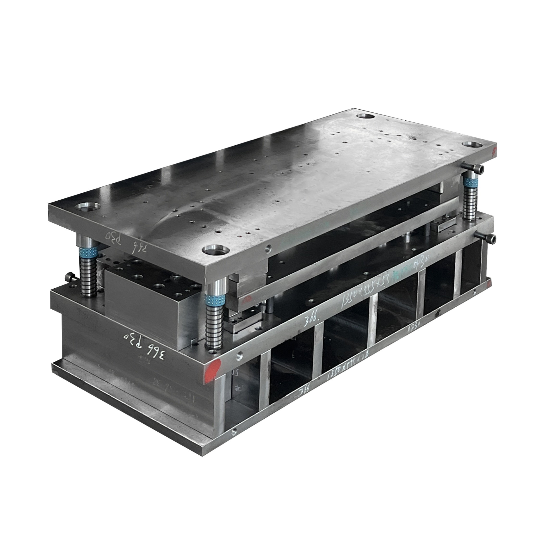
Base And Die Shoes Assembly
Imagine starting with the foundation: the lower die shoe. This thick steel plate forms the base of your die set, providing support and stability for every other component. The upper die shoe mirrors this on top, and together they form the backbone of the die for press operations. Both shoes are machined with tight tolerances to ensure flatness and parallelism. Precision dowel pins are installed in the lower die shoe to establish accurate, repeatable location for the upper die shoe—think of them as the reference points that prevent misalignment during assembly and operation. These shoes also feature mounting holes for attaching the die to the press and for securing other components like guide pins and bushings.
- Place the lower die shoe on a clean, stable surface.
- Install precision dowel pins and fasteners into the lower die shoe to define datum locations.
- Mount guide pins vertically into the lower die shoe, ensuring perpendicularity and secure fit.
- Fit bushings into the corresponding holes in the upper die shoe. These bushings will mate with the guide pins for precise alignment.
- Position the upper die shoe above, lowering it so the guide pins enter the bushings smoothly, aligning the entire assembly.
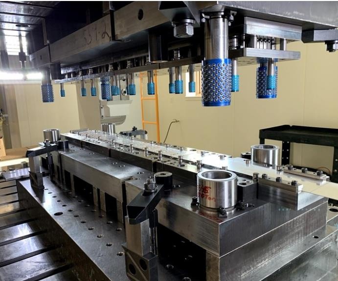
Guiding Stack With Precision
The guiding system—comprising guide pins and bushings—ensures that the upper and lower halves of the die move in perfect sync. Guide pins (sometimes called guide posts or pillars) are typically made from hardened tool steel and ground to extremely tight tolerances, often within 0.0001 inch. There are two main types: friction pins and ball bearing pins. Friction pins offer robust guidance when side thrust is expected, while ball bearing pins are preferred for high-speed stamping due to their reduced friction and easier separation of die halves. The bushings, also precision-ground, are pressed into the upper die shoe and mate with the guide pins to maintain alignment through every press cycle[source].
Cutting And Stripping Elements
Next, the cutting and stripping components are installed. Punches are fixed into retainers on the upper die shoe, ready to push through the metal sheet. The button die (or die button) is mounted in the lower die shoe, providing the matching cutting surface for the punch. Between these, a stripper plate or stripper tube (sometimes using urethane springs for controlled force) is positioned to hold the workpiece and strip it off the punch after cutting. Urethane springs or traditional die springs are preloaded to deliver consistent stripping force, ensuring parts don’t stick to the punch or get damaged during ejection. The precise fit and planarity of the stripper are essential—if it’s not level or properly supported, you’ll see uneven wear or part defects.
| Component | Purpose | Alignment Surface | Typical Tolerance Notes |
|---|---|---|---|
| Lower Die Shoe | Foundation, supports all lower components | Mounting face, dowel pin holes | Primary datum, machined for flatness |
| Precision Dowel Pins | Repeatable location, prevent rotation | Press-fit holes in die shoes | Fit hierarchy: datum first, then clearance |
| Guide Pin | Align upper and lower die shoes | Guide pin bore, bushing | Precision ground, minimal clearance |
| Bushing | Receives guide pin, maintains alignment | Press-fit in upper die shoe | Matched to guide pin, tight fit |
| Punch | Cuts or shapes material | Punch retainer, stripper plate | Secured for minimal movement |
| Button Die | Provides cutting edge for punch | Mounted in lower die shoe | Offset for punch-die clearance |
| Stripper Plate/Tube | Strips part from punch, supports workpiece | Mounted between punch and die | Planarity and preload critical |
| Urethane Springs | Provide stripping force | Seated in pockets or guides | Preload checked per spec |
- Always clean mating surfaces thoroughly before assembly to prevent misalignment.
- Avoid shimming unless specified in the design—shims can introduce unwanted gaps or stack-up errors.
- Check preload on die springs or urethane springs to ensure consistent stripping and ejection.
- Confirm stripper plate or tube planarity to avoid uneven wear and part defects.
- Design for easy punch change access to simplify maintenance and reduce downtime.
By visualizing this sequence and understanding the function of each component, you’ll be better equipped to spot assembly issues, communicate effectively with your build team, and ensure your stamping die delivers consistent, high-quality results. Next, we’ll explore how design calculations—like punch-to-die clearance and press tonnage—drive the choices you make for these components.
Design Calculations That Drive Better Choices
When you’re tasked with stamping die design, it’s tempting to reach for software or pre-set calculators. But what if you want to truly understand why a certain clearance or tonnage is needed? Let’s break down the foundational calculations and logic paths that underpin every durable and efficient metal stamping die design—no proprietary black boxes required.
Punch To Die Clearance Fundamentals
Ever noticed how a clean, burr-free edge on a punched part makes downstream assembly easier? That’s not luck—it’s the result of carefully chosen punch-to-die clearance. In sheet metal stamping dies, clearance is the distance between the cutting edge of the punch and the edge of the die opening (the die button). This gap must be just right: too tight, and you’ll accelerate tool wear and risk punch breakage; too loose, and you’ll see rough edges, burrs, or deformed parts.
Clearance is typically set as a percentage of the sheet thickness, and the optimal value depends on both the material’s hardness and its thickness. Harder or thicker materials require a larger clearance, while softer or thinner materials need less. For example, as explained by MISUMI, a common starting point is 10% of the stock thickness per side, but this may increase for tougher materials or to extend tool life. Adjusting clearance also directly impacts energy efficiency and the quality of the cut edge. Regular inspection of punch parts and die buttons for burrs or excessive wear can help you fine-tune these settings for your application.
Press Tonnage Estimation Framework
How do you know your press die punch setup won’t overload the press—or leave it underused? Calculating required tonnage is a must for any sheet metal die project. The basic logic is straightforward: sum up the loads from all operations (piercing, blanking, forming, bending, etc.) that occur in a single stroke. The most common formula for blanking or piercing is:
- Required Tonnage = Perimeter of Cut × Material Thickness × Shear Strength
This approach ensures you account for the entire cut length, the material’s resistance, and its thickness. For forming or drawing operations, substitute ultimate tensile strength for shear strength, as the material is being pulled rather than sheared. Don’t forget to add extra force for any spring strippers, cams, or carrier cutting operations—these can add up quickly in complex punch press dies[source]. As a best practice, always include a safety margin to account for tool wear or unexpected material variation.
Stroke Sequencing And Timing
Ever had a part stick to the punch or a form misalign? That’s often a timing issue. In progressive or multi-stage sheet metal stamping dies, the sequence and timing of each operation are critical. Operations like pilot hole punching must occur before forming or bending, and strippers must engage at just the right moment to avoid double hits or misfeeds. Cam-driven actions (for side forms) need to be timed so they don’t clash with the main punch stroke.
| Design Objective | Inputs | Typical Output/Decision |
|---|---|---|
| Punch-to-Die Clearance | Material type, thickness, desired edge quality, tool life goals | Clearance value (% of thickness), punch and die button sizing |
| Press Tonnage | Perimeter, thickness, shear/ultimate strength, number of operations | Press selection, safety margin, die station layout |
| Stroke Sequencing | Part features, operation dependencies, cam actions | Station order, timing of strippers/pilots/cams |
Inadequate clearance increases burr height and tool wear, while excessive clearance degrades edge quality and part accuracy.
- Set stripper timing so the stripper plate contacts the sheet just before the punch enters the material.
- Ensure pilot punches engage before forming or bending to maintain positional accuracy.
- Check cam timing to prevent interference with main stroke or part ejection.
By grounding your choices in these calculation frameworks, you’ll make better decisions about die components, press sizing, and process layout—leading to more reliable production and fewer surprises on the shop floor. Next up, we’ll look at how controlling lateral loads through component selection can further protect your die and ensure consistent results.
Control Lateral Loads With Smart Component Choices
Ever wonder why a stamping die that works perfectly for months suddenly starts producing parts with burrs, misalignment, or even jammed side actions? Often, the root cause is lateral (side) loads—forces that push sideways on your die set, not just up and down. If you want to maximize the lifespan of your stamping die components and maintain precise part quality, controlling these side loads with the right component selection and layout is essential. Let’s break down where these forces come from, how they travel through your die, and which features you can optimize to keep your process running smoothly.
Identifying Lateral Load Sources
Picture a stamping operation where the part geometry is off-center, or a cam-driven feature (like a rolling cam or aerial cam) forms a flange from the side. These scenarios introduce significant lateral forces into the die system. Even something as simple as uneven stock feed or an asymmetric blank can push the upper and lower die shoes sideways against each other. If these forces aren’t controlled, you’ll see wear on guiding elements, misaligned cuts, or even damaged cam components. Recognizing these load paths early allows you to reinforce vulnerable areas and choose the right guiding and support features.
| Observed Symptom | Likely Load Path | Component/Feature To Optimize |
|---|---|---|
| Punched holes shift or parts show uneven burrs | Lateral force from off-center forming or cam action | Increase guide span, use ball bushings for lower friction |
| Guide pins or bushings show scoring/wear on one side | Unbalanced side thrust during stroke | Add heel blocks/slide plates, check alignment of die shoes |
| Side-action cams jam or fail to return | Improper cam alignment, insufficient anti-rotation | Upgrade to box cam with anti-rollback, add gibs or guides |
| Cam components or press cam units wear prematurely | High friction or misapplied force in cam track | Use rolling cam followers, optimize lubrication, select correct cam profile |
Guiding And Bearing Strategies
How can you ensure your die set resists these side loads? It starts with the guiding system. Guide pins and bushings are the primary defense against lateral movement. For dies with high side thrust—such as those with heavy forming or cam-driven actions—choosing the right type of guide stack is critical:
- Friction (plain) guide pins and bushings: Simple and robust, these offer good resistance to side loads but generate more friction and heat at high speeds. They’re often lined with aluminum-bronze and may include graphite plugs for self-lubrication.
- Ball bushing (ball bearing) guide pins: These reduce friction dramatically and allow higher-speed operation. They’re ideal for dies where fast cycling or easy separation is needed, but may be less tolerant of heavy, one-directional side thrust unless paired with heel blocks or slide plates[source].
Pros and Cons: Guide Pin/Bushing Types
-
Friction Pins
- Pros: High side-load capacity, cost-effective, simple maintenance
- Cons: Higher friction, not suited for high-speed stamping, harder die separation
-
Ball Bushings
- Pros: Low friction, easy die separation, precise alignment
- Cons: Less tolerant of heavy side loads without supplemental heeling, higher cost
Slide plates (sometimes called wear plates) and heel blocks are often added to the die shoes to further resist side thrust. Slide plates, made from dissimilar metals to reduce galling, absorb and distribute lateral loads, especially in dies with significant cam or off-center actions.
Pros and Cons: Slide Plates vs. Linear Bearings
-
Slide Plates
- Pros: Durable under heavy side loads, simple to service, cost-effective
- Cons: Require regular lubrication, may wear faster under high-speed cycles
-
Linear Bearings
- Pros: Smooth motion, low friction
- Cons: Sensitive to contamination, less robust under impact or heavy thrust
Cam Design And Anti-Rotation
Cam components—such as rolling cam units, box cams, or aerial cams—are used to drive motions that can’t be accomplished by a simple vertical press stroke. But cams also introduce complex side loads that can cause premature wear or jamming if not properly guided. A press cam or side-action cam needs anti-rotation features (like gibs, heel blocks, or anti-rollback devices) to keep the cam follower and slide aligned throughout the motion cycle.
Pros and Cons: Cam Variants
-
Box Cam
- Pros: Excellent anti-rotation, handles high side loads, suited for complex side actions
- Cons: Larger footprint, more complex machining and assembly
-
Aerial Cam
- Pros: Flexible for upper die actions, enables intricate forms
- Cons: Can be more sensitive to misalignment, requires precise timing
-
Rolling Cam
- Pros: Lower friction, smoother action, longer component life
- Cons: May require more precise lubrication and maintenance
Controlling lateral deflection through smart component selection not only protects edge quality but also extends the life of your die and its most critical parts.
By proactively addressing lateral loads—whether through wider guide spans, strategic use of ball bushings, or upgrading to box cam assemblies—you’ll prevent many of the most common die failures. This approach ensures your stamping die components work in harmony, delivering consistent results and minimizing downtime. In the next section, we’ll explore how different die types employ these components to balance complexity, cost, and performance for your specific application.
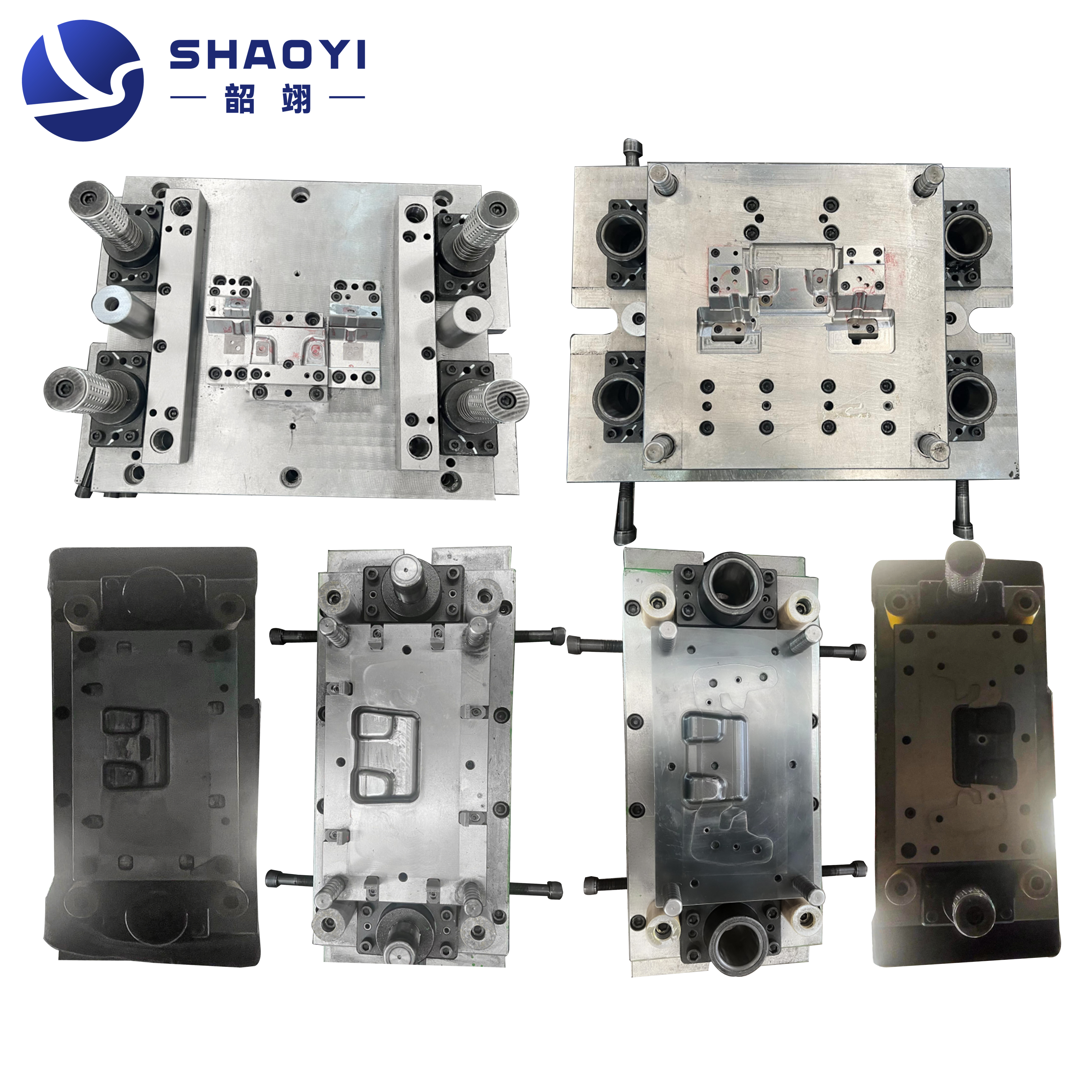
Which Components Each Die Type Really Uses
When you’re choosing between types of stamping dies, you might wonder: Does every die need a complex stack of guides, sensors, and cams—or can you simplify to save cost and speed up delivery? The answer depends on the die style and its intended application. Let’s break down how progressive die components, compound die stamping setups, and transfer dies compare, so you can right-size your approach without sacrificing quality or performance.
Progressive Die Essentials
Progressive die metal stamping is all about efficiency in high-volume runs. Imagine a strip of sheet metal advancing through a series of stations, each performing one operation—piercing, forming, trimming—before the finished part is separated at the final station. To make this work, progressive dies rely on:
- Pilots and pilot lifters: Ensure the strip is precisely located at each station.
- Stock guides: Keep the material aligned as it feeds.
- Strippers: Remove the part or scrap from punches after each stroke.
- Sensors: Optional, but increasingly common for misfeed or double-hit detection.
Carriers—features in the strip that hold workpieces as they move—are typical in progressive dies but rare elsewhere. Cams are used when side actions are needed, but not every progressive die requires them.
Compound And Single Station Differences
Compound die stamping focuses on producing simple, flat parts in a single press stroke. Here, the upper and lower die sections perform multiple operations (such as blanking and piercing) simultaneously. You’ll notice:
- Rigid alignment features: Dowel pins and robust guide posts are essential for accuracy.
- Strippers: Still required, but usually simpler than in progressive dies.
- Pilots: Sometimes included, but less critical if the part is a single blank.
- Cams and sensors: Rare, since most compound dies don’t need complex motions or feedback.
For single-station or simpler sheet metal dies, you might only find the basic press die components—like punches, die buttons, and a stripper—without added automation or sensors.
Transfer Die Considerations
Transfer die stamping is like an assembly line for larger, more complex parts. Here, each station performs a different operation, and the part is moved (transferred) from station to station, often by mechanical arms. This method is ideal for intricate shapes or when a part needs multiple bends, draws, or trims that can’t be done in a single hit. In transfer dies, you’ll typically see:
- Carriers or transfer fingers: Move the part between stations.
- Cams: Common for complex forms or side actions.
- Sensors: Frequently included to monitor position and part presence.
- Stock guides: Sometimes needed, but less critical since the part is separated from the strip early.
Transfer dies offer flexibility for both short and long production runs, but their setup is more complex and often requires more advanced press die components and maintenance routines.
| Component Group | Progressive Die | Compound Die | Transfer Die |
|---|---|---|---|
| Pilots/Pilot Lifters | Typical | Optional | Rare |
| Stock Guides | Typical | Optional | Optional |
| Strippers | Typical | Typical | Typical |
| Cams | Optional | Rare | Typical |
| Sensors | Optional | Rare | Typical |
| Carriers/Transfer Fingers | Typical (as strip features) | Rare | Typical (mechanical) |
- Part complexity: More features or bends often require cams, carriers, or sensors.
- Tolerance stack-up: Tight tolerances may demand more precise guides and feedback.
- Run rate: High-volume jobs benefit from automation (pilots, sensors, carriers).
- Press capabilities: The available press stroke, tonnage, and automation options influence which types of dies and components are feasible.
Selecting the minimal effective component set for your die type helps reduce tryout time and maintenance—without compromising quality.
Understanding the real differences in press die components across progressive, compound, and transfer dies gives you the confidence to specify only what you need. Next, we’ll look at how material and surface choices further impact lifespan and performance, helping you refine your decision-making even more.
Materials Heat Treat And Coatings That Last
When you’re planning for long-lasting, high-precision metal forming dies, it’s not just about the design—your choice of die material, heat treatment, and surface finish will make or break the lifespan and performance of every die section and component. Sounds complex? Let’s break it down into clear, actionable steps, so you can confidently match your stamping die components to your production goals and cost targets.
Selecting Die Steels And Blocks
Start by asking: What type of parts are you stamping, and how many do you need? For high-volume runs, tool steel is the industry standard for steel stamping dies, offering a balance of wear resistance and toughness. H-13 and D-2 are common choices—H-13 for its shock resistance and D-2 for its superior wear properties. If you’re working with abrasive materials or require ultra-high precision, carbide punches or inserts may be the answer, as they deliver excellent edge retention and minimal deformation over time. For prototype or low-volume jobs, pre-hardened die blocks can reduce cost and lead time, though they may not last as long in demanding applications.
| Option | Wear Resistance | Toughness | Grindability | Typical Use |
|---|---|---|---|---|
| Tool Steel (H-13) | High | Excellent | Good | High-volume metal forming dies, die blocks |
| Tool Steel (D-2) | Very High | Moderate | Moderate | Long runs, abrasive materials, blanking dies |
| Carbide | Exceptional | Low (brittle) | Challenging | Carbide punches, wear inserts for extreme tool life |
| Pre-hardened Steel | Moderate | Good | Excellent | Prototype dies, low-volume die section builds |
- Part material: Softer stocks may allow less wear-resistant steels; abrasive materials demand higher-grade die material or carbide.
- Expected production volume: Higher volumes justify investment in premium tool steels or carbide punches.
- Edge-quality expectations: Tight tolerances and clean edges require harder, more stable materials and careful heat treat.
- Maintenance intervals: Frequent tool changes or sharpening favor materials with good grindability.
- Press speed: High-speed presses can cause thermal fatigue; choose materials and treatments that resist heat softening.
Heat Treat Paths And Stability
Imagine assembling a die block from the best steel—only to see it crack or warp after heat treatment. Proper heat treat isn’t just a checkbox; it’s the key to unlocking the full potential of your die material. For tool steels like H-13, the process follows a precise sequence: preheating (to avoid thermal shock), austenitizing (to achieve the right microstructure), rapid quenching (for hardness), and tempering (to balance hardness and toughness). Each stage must be carefully controlled—too fast, and you risk distortion; too slow, and you may not reach the desired properties. Always review the furnace chart and confirm the process meets your die specification[source].
Consistent heat treat practices ensure your die section maintains dimensional accuracy and resists fatigue or chipping, especially in high-volume metal forming dies. For carbide punches, heat treat is less relevant, but how the carbide is bonded and finished still impacts tool life.
Coatings And Surface Treatments
Even the hardest die block can wear out prematurely without the right surface engineering. Surface treatments and coatings add a protective layer, reducing friction, wear, and corrosion. Common techniques include:
- PVD (Physical Vapor Deposition) coatings: Thin, hard layers that reduce galling and improve wear resistance, ideal for ferrous materials.
- Nitriding: Diffuses nitrogen into the steel surface, creating a hard, wear-resistant layer with minimal distortion—perfect for complex die sections.
- Thermal barrier coatings: Help manage heat in high-speed or high-load applications.
- Corrosion-resistant coatings: Essential for dies exposed to humid or chemically aggressive environments.
- Advanced options: Plasma nitriding, nanocomposite coatings, and even self-healing coatings are emerging for next-level durability and reduced downtime.
Surface treatments can also improve material flow and part quality by minimizing adhesion between the workpiece and die, especially in high-precision stamping operations.
Material and coating choices should always be validated with sample runs and inspected for distortion before final grind—protecting both your investment and your process stability.
By matching your die material, heat treat, and surface engineering to your unique application, you’ll achieve longer tool life, more consistent part quality, and lower total cost of ownership. Next, we’ll translate these material choices into a practical sourcing and supplier comparison framework—helping you move from design to execution with confidence.
Procurement Checklist and Supplier Comparison for Automotive Stamping Dies
Ready to move from die design to sourcing? Imagine you’re preparing to request quotes—what exactly should you include, and how do you compare stamping dies manufacturers to ensure your investment in stamping die components pays off for years to come? Let’s break down a practical approach, so your team can confidently navigate the world of stamping die manufacturing and choose partners who will deliver on quality, cost, and support.
What To Put In Your RFQ
When you send out a Request for Quotation (RFQ) for automotive stamping dies or any metal stamping tooling, clarity is your best friend. Incomplete or vague RFQs lead to inconsistent quotes and costly surprises down the road. Here’s a checklist of must-have fields for a robust RFQ:
- Material specification and required heat treatment
- Surface finish requirements (e.g., coating, polishing, nitriding)
- Dimensional tolerances and critical feature callouts
- Expected die life (production volume targets)
- List of spare and wear parts (e.g., punches, springs, die sections)
- Maintenance plan and recommended intervals
- Inspection and acceptance criteria (including sample part approval)
- Any special requirements (e.g., CAE simulation, FMEA, certifications)
Comprehensive RFQs help manufacturers accurately estimate costs, select the right press die set, and avoid miscommunication later on. According to industry guides, detailed drawings, material specs, and finish requirements are essential for accurate quotes and quality parts.
How To Compare Die Manufacturers
Once the quotes arrive, how do you evaluate them beyond price? Imagine lining up each stamping dies manufacturer side by side—what sets the leaders apart? Here’s a comparison table to help you see the differences at a glance:
| Manufacturer | Certifications | CAE/Simulation | Engineering Collaboration | Tryout Reduction Strategy | Inspection & Reporting | Launch & Support |
|---|---|---|---|---|---|---|
| Shaoyi Metal Technology | IATF 16949 | Advanced CAE for geometry and material flow | In-depth reviews, formability analysis | Simulation-driven, reduced tryout cycles | Comprehensive inspection, documentation | Prototype to mass production, global support |
| Supplier B | ISO 9001 | Basic CAD/CAM | Standard engineering review | Traditional trial-and-error | Standard inspection reports | Launch support on request |
| Supplier C | None listed | Manual calculations | Limited collaboration | Longer tryout period | Basic dimensional check | Minimal support post-launch |
Look for suppliers who invest in technology, offer full engineering support, and maintain clear communication throughout the stamping die manufacturing process. Certifications like IATF 16949 or ISO 9001 signal robust quality management systems, especially for automotive stamping die projects. Ask about their production capacity, track record, flexibility, and whether they can scale as your needs grow. Visiting facilities, reviewing case studies, and speaking with references can further validate your choice.
Risk Reduction With Simulation and Certification
Why do some metal stamping die manufacturers consistently deliver dies that hit the ground running, while others require multiple costly adjustments? The answer often lies in the use of advanced simulation and strict certification standards. CAE (Computer-Aided Engineering) tools allow manufacturers to predict material flow, spot potential forming issues, and optimize die geometry before cutting steel—reducing the number of tryout cycles and minimizing costly rework. IATF 16949 and ISO certifications ensure that process controls are in place for consistent quality and traceability.
When evaluating a stamping dies manufacturer, ask about their simulation capabilities, inspection methods, and how they manage design changes. A supplier who offers proactive risk management, clear documentation, and ongoing support will help you avoid common pitfalls and achieve smoother production launches.
Choosing a die supplier is about more than price—look for proven technology, robust support, and a commitment to quality that matches your project’s needs.
With these tools and frameworks, you’re equipped to make informed decisions as you source stamping die components. Up next, we’ll cover how disciplined maintenance routines protect your investment and keep your press die set running at peak performance.
Maintenance Routines And Confident Next Steps
Ever noticed how a well-maintained die set keeps production humming while neglected dies lead to costly downtime and inconsistent parts? Protecting your investment in stamping die components isn’t just about having the right design—it’s about disciplined, repeatable maintenance routines that keep every guide pin, punch, and die section performing at its best. Let’s walk through practical steps and troubleshooting tips you can apply on the shop floor, whether you’re working with heavy duty die springs, ball bushings, or the latest press die parts.
Pre Shift Checks
Imagine starting your shift knowing every die component is ready for action. Pre shift checks are your first line of defense against surprises. Here’s a simple checklist to follow before each run:
- Clean all exposed die surfaces to remove debris, metal slivers, or lubricant buildup. Use approved solvents or cleaners as recommended for your die material.
- Lubricate guide pins, ball bushings, and wear plates according to your maintenance plan. Don’t forget the stripper mechanism and any moving cams.
- Verify fastener torque on mounting bolts, stripper plates, and critical die components. Loose bolts can lead to misalignment or damage.
- Check die springs (including heavy duty die springs) and urethane elements for proper preload and visible wear or cracking.
- Visually inspect punches, button dies, and die sections for chipping, excessive wear, or burr formation.
Weekly And Monthly Inspection
Beyond daily checks, routine inspections catch issues before they escalate. Schedule these inspections based on production volume and die complexity:
- Disassemble and deep-clean key die components—especially punches, stripper plates, and press die parts prone to buildup.
- Check alignment of guide pins and bushings with a mandrel or fixture. Even slight misalignment can cause uneven wear or part defects.
- Sharpen punch and die edges as needed using the correct grinding wheel and technique to avoid overheating.
- Inspect die springs and ball bushings for fatigue or loss of force. Replace any that show signs of sagging or cracking.
- Document all findings and corrective actions for traceability and future troubleshooting.
Troubleshooting And Corrective Actions
What if you start seeing burrs, misfeeds, or sticking parts? Quick, targeted troubleshooting helps you get back on track:
| Failure Mode | Action |
|---|---|
| Rising burrs on parts | Inspect punch and button die wear; verify punch-to-die clearance; sharpen or replace as needed |
| Misfeeds or jammed strip | Check stock guides, pilots, and strip alignment; clean and adjust as necessary |
| Galling on punches or die sections | Review lubrication schedule and coating condition; reapply or upgrade coatings if needed |
| Spring or stripper failure | Replace damaged die springs or urethane elements; verify preload and alignment |
| Loose or shifting components | Retorque all fasteners; inspect for worn mounting holes or dowel pins |
- Rising burrs → Inspect punch wear and clearance
- Misfeeds → Verify stock guides and pilots
- Galling → Review coatings and lubrication
- Spring breakage → Replace heavy duty die springs, check preload
- Component misalignment → Use inspection fixtures to verify datums
For critical features, consider adding simple inspection fixtures or go/no-go gauges to check datums and key dimensions quickly—this reduces human error and ensures repeatability.
For those seeking deeper insights into maintenance planning, CAE-informed handoff documentation, and best practices for automotive stamping die care, it’s worth consulting resources like Shaoyi Metal Technology. Their approach—combining IATF 16949 certification and CAE simulation—illustrates how digital analysis can inform not just die design but also routine and preventive maintenance, making it easier to clarify care requirements and minimize unexpected downtime.
Disciplined, regular inspection and maintenance are the surest way to prevent costly production stops and extend the life of your stamping press parts.
With these routines in place, you’ll protect your investment in die components and ensure every production run meets your quality and delivery targets. Ready to put these steps into action? A robust maintenance plan is your next step toward stamping success.
Frequently Asked Questions About Stamping Die Components
1. What are the essential components of a stamping die?
Key stamping die components include guide pins and bushings for alignment, punches and die buttons for cutting, strippers and springs for part removal, cams for complex motions, and sensors for process monitoring. Each component ensures precise part formation and reliable operation in metal stamping dies.
2. How do I choose the right material for stamping die components?
Selecting die materials depends on production volume, part material, and required durability. Tool steels like H-13 and D-2 are common for high-volume runs due to their wear resistance and toughness. For abrasive or high-precision jobs, carbide punches and inserts may be used. Coatings and heat treatments further enhance component life and performance.
3. What is the difference between progressive, compound, and transfer dies?
Progressive dies perform multiple operations as the sheet advances through stations, ideal for high-volume parts. Compound dies complete several actions in a single stroke, suitable for simpler shapes. Transfer dies use mechanical arms to move parts between stations, allowing for complex forms and high flexibility in part design.
4. How does proper maintenance impact stamping die performance?
Regular maintenance—such as cleaning, lubrication, inspection, and timely replacement of worn parts—prevents defects, reduces downtime, and extends the lifespan of stamping die components. Disciplined routines are vital for maintaining quality and minimizing production interruptions.
5. What should I include in an RFQ for automotive stamping dies?
An effective RFQ should specify material and heat treat requirements, surface finish, tolerances, expected die life, spare parts lists, maintenance plans, and acceptance criteria. Including simulation and certification requirements, like IATF 16949, helps ensure manufacturers meet your quality and performance standards.