 Small batches, high standards. Our rapid prototyping service makes validation faster and easier —

Transfer Die Stamping Explained: Cut Scrap, Boost Yield Fast
Transfer Die Fundamentals
Ever wondered how manufacturers shape complex, three-dimensional metal parts? The answer often lies in the transfer die—a specialized metal stamping process that stands apart from more familiar methods like progressive dies or compound dies. Understanding the differences is key to choosing the right approach for your project, whether you’re after deep draws, intricate forms, or high-volume efficiency.
What is a transfer die?
A transfer die is a type of stamping die that moves individual metal blanks from one station to the next inside a press. Unlike progressive stamping, where the part stays attached to a metal strip throughout the process, transfer die stamping separates the blank at the very first step. Mechanical transfer fingers (or grippers) then shuttle the part through a series of operations—such as drawing, bending, piercing, and trimming—allowing for multi-directional forming and the creation of large or highly contoured parts. This flexibility makes transfer die stamping ideal for manufacturing components like automotive shells, frames, and deep-drawn housings that demand complex shapes and varied forming actions.
- Blanking: Cutting an initial flat shape (blank) from sheet metal.
- Piercing: Creating holes or cutouts in the blank.
- Forming: Bending or shaping the metal into three-dimensional contours.
- Trimming: Removing excess material after forming.
- Flanging: Bending the edge of a part to add strength or allow assembly.
Transfer die vs progressive die essentials
In progressive stamping, a continuous metal strip advances through multiple stations, each performing a specific operation. The part remains attached to the strip until the final cut. This process is fast and cost-effective for high-volume runs of smaller, less complex parts—think brackets, clips, or electronic connectors. However, because the part is always tethered to the strip, progressive dies are less suited for deep draws or parts with complex geometry.
Where compound die fits in
Compound dies perform multiple operations—typically blanking and piercing—in a single press stroke. They are best for simple, flat parts where high precision is needed, but they lack the flexibility for multi-directional forming or deep draws.
| Process | Part Complexity | Part Size | Material Draw Depth |
|---|---|---|---|
| Transfer Die | High (multi-form, 3D shapes) | Medium to Large | Deep draws supported |
| Progressive Die | Low to Medium (strip-friendly) | Small to Medium | Shallow to moderate |
| Compound Die | Low (simple, flat parts) | Small to Medium | Minimal |
Choose transfer dies when part geometry requires free-form movement and multi-directional forming beyond what a strip can support.
When to choose transfer tooling
Imagine you need a deep-drawn shell or a structural panel with flanges on multiple sides. Progressive dies would struggle to support the part through each stage, while a compound die couldn’t handle the forming complexity. Transfer die stamping, with its ability to move and orient each blank independently, is the go-to for these challenging shapes. It’s especially valuable for both short and long production runs where flexibility and part complexity outweigh pure speed or cost-per-piece.
Now that you know the fundamentals of transfer die stamping and how it compares to progressive and compound dies, the next section will walk you through the operational workflow—revealing how parts move from blanking to finished product with precision and care.
The Transfer Die Stamping Workflow
When you hear about transfer die stamping, you might picture a complex ballet of metal, machinery, and automation. But how does a blank piece of metal transform into a finished component with such precision? Let’s walk through the practical steps, from raw coil to the final offload, and demystify the transfer stamping process so you can visualize what really happens on the shop floor.
End-to-End Transfer Die Stamping Workflow
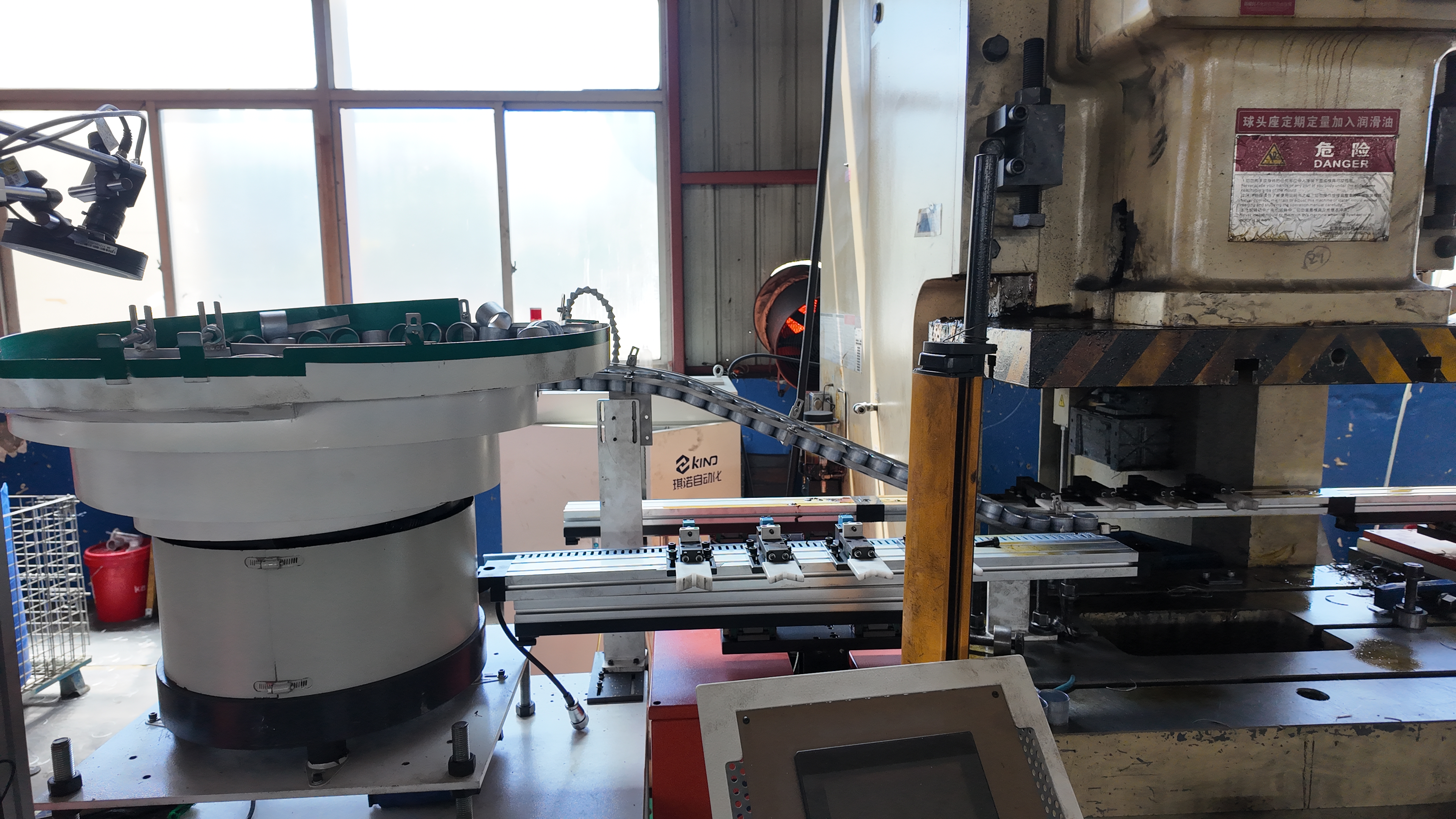
Imagine a massive coil of metal feeding into a transfer stamping press. Here’s how the journey unfolds step by step:
- Blanking: The process begins as the coil is uncoiled and fed into the press. The first station cuts out flat blanks from the strip, separating them from the parent material. Sometimes, blanks are prepared offline and loaded via a de-stacker instead.
- First Draw: The blank moves to the next station, where it’s deep-drawn or shaped into a basic three-dimensional form.
- Redraw: If the part requires a deeper or more refined shape, a redraw station further stretches or forms the metal.
- Restrike: Additional stations may restrike the part to sharpen features or improve precision.
- Trimming: Excess material is trimmed away, leaving only the final part outline.
- Piercing: Holes or cutouts are punched according to the part design.
- Flanging: Edges are bent or flanged to strengthen the part or prepare it for assembly.
- Offload: The finished part is transferred out of the die-stamping machine, often onto a conveyor or directly into a container.
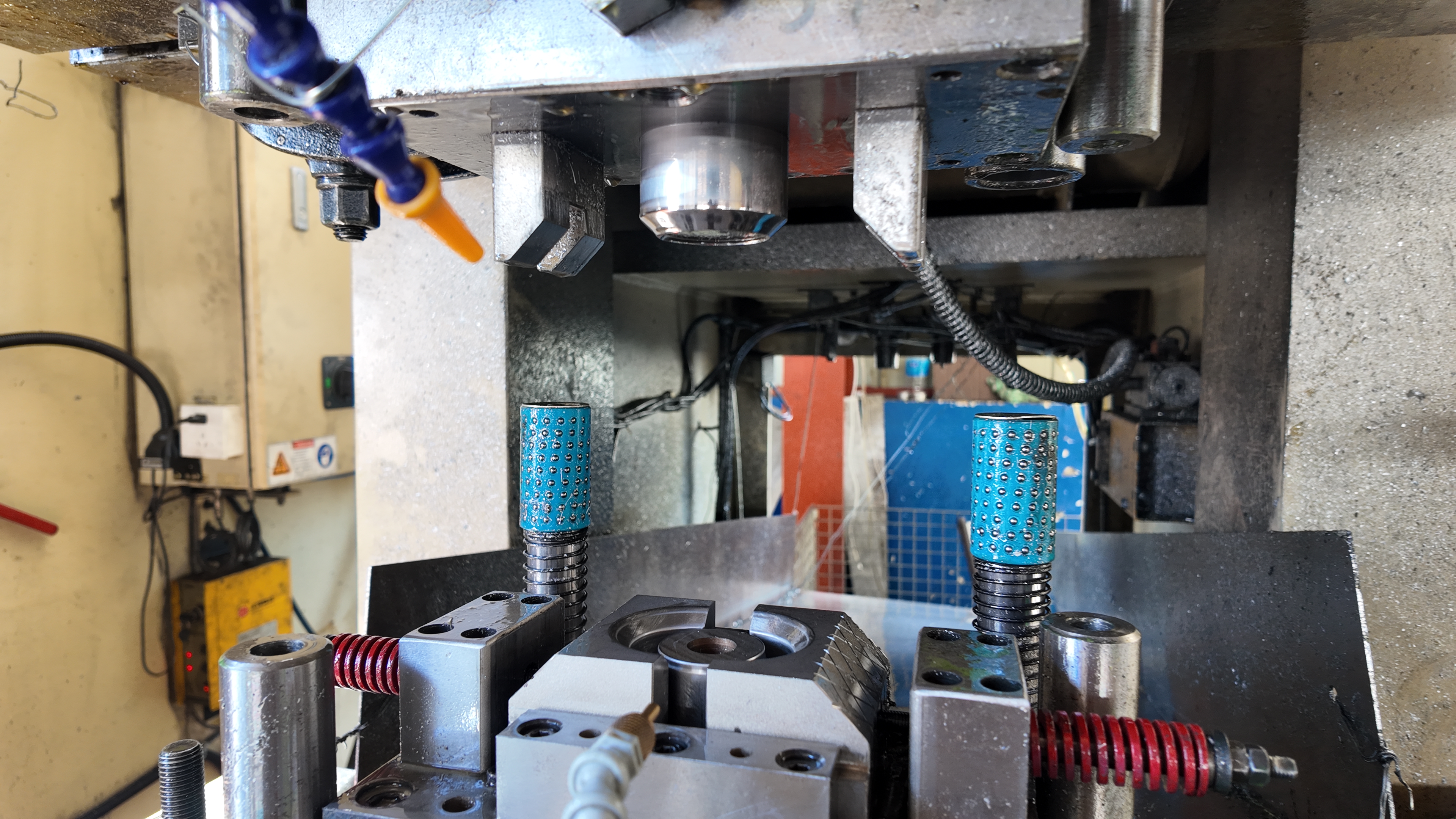
Throughout this process, it’s the transfer mechanism—rails with fingers or grippers—that moves each blank from station to station, ensuring precise placement and timing at every step.
Transfer Fingers and Gripper Selection
Not all parts are handled the same way. The choice of gripper technology is critical and depends on the part’s shape, material, and surface requirements. Here’s a quick comparison:
| Gripper Type | Best For | Trade-offs |
|---|---|---|
| Mechanical Fingers | Rigid, robust parts; high precision placement; harsh environments | Strong grip, but may mark delicate surfaces or require custom jaws |
| Vacuum Cups | Flat, smooth, or large panels; delicate or cosmetic surfaces | No surface marking, but less effective on textured/porous parts; higher air consumption |
| Magnetic Grippers | Ferrous metals; textured or oily surfaces | Fast and energy-saving, but only for magnetically responsive materials |
For example, mechanical grippers excel in automotive transfer stamping where strength and repeatability matter, while vacuum cups are favored for appliance panels with pristine finishes.
Sequencing and Timing to Protect Surfaces
Coordinating the handoff between stations is all about timing. As the press opens, transfer rails move in, grippers close on the part, and the assembly lifts, shifts, and precisely places the blank at the next operation—all before the press descends again. This choreography is typically managed by timing cams or modern servo-driven systems, which allow for fine-tuned sequencing and dwell times to prevent twisting, scuffing, or misalignment.
To ensure smooth operation, setup checks are essential before running a die-stamping machine. Here’s a quick list:
- End-of-arm alignment (fingers or cups must match part geometry)
- Sensor verification (part presence, position, and press status)
- Lubrication paths (to minimize friction and surface defects)
- Gripper force calibration (to avoid part deformation)
- Safety interlocks and light curtain functionality
Always verify that all safety interlocks and light curtains are active before running a transfer stamping press. Operator safety is paramount.
By carefully selecting gripper types, sequencing movements, and performing diligent setup checks, you ensure that each part moves seamlessly through the transfer press stamping process—yielding consistent quality and minimizing scrap. In the next section, we’ll explore how robust die design and thoughtful station layout further enhance process stability and part quality.
Designing Robust Transfer Dies That Run Right
When you look at a finished stamped part, have you ever wondered what decisions make that part consistent, precise, and cost-effective? The answer lies in the thoughtful design of transfer dies. A robust die design isn’t just about getting metal from point A to point B—it’s about ensuring every station, every component, and every motion supports stability, quality, and efficient production. Let’s break down the essentials for designing transfer dies that deliver repeatable results, minimize scrap, and keep your stamping operation running smoothly.
Structuring Stations for Stability and Quality
Sounds complex? It can be, but a systematic approach makes all the difference. Start by mapping out the part’s features and defining the ideal sequence of operations. For example, blanking should typically come first, followed by drawing (to create the part’s basic shape), then restriking (to sharpen details), trimming, piercing, and finally flanging. Each stage should be logically ordered to avoid interfering features and to maintain part integrity throughout the process.
- Material spec and thickness: Choose material and gauge based on formability and end-use requirements.
- Draw depths: Deep draws may require additional stations or specialized draw beads to manage metal flow.
- Critical radii: Ensure bends and corners meet part tolerance and reduce the risk of cracking.
- Hole positions: Plan pierce locations after major forming to prevent distortion.
- Flange angles: Sequence flanging after trimming for cleaner edges.
- Surface class: Identify cosmetic areas needing extra protection or finish control.
- Coating: Allow for any added coatings or surface treatments in the station plan.
Die Components That Matter Most
Imagine the die as a team—every component has a role in supporting quality and process reliability. Here’s what you’ll notice in robust stamping dies and metal stamping tooling:
- Addendum design: Smooth transitions and addenda guide material flow, reducing thinning and wrinkling during forming.
- Draw beads and pressure pads: These features control how metal stretches, helping to avoid splits and wrinkles, especially in deep-drawn shapes.
- Pilots and cam operations: Pilots ensure precise part positioning at each station, while cams enable side actions like lancing or forming tabs that can’t be achieved in a straight stroke.
- Sensorization: Integrate sensors for part presence, tonnage monitoring, and die protection to catch issues early and prevent costly downtime.
- Stripper designs: Strippers help remove the part from punches and dies cleanly, reducing the risk of jams or double-hits.
- Lubricant delivery: Well-placed lubrication paths minimize friction, protect surface finish, and extend tool life.
| Feature Risk | Design Countermeasure |
|---|---|
| Deep draw | Bead tuning, addendum optimization, pressure pad use |
| Springback | Restrike stations, over-bending, cam re-striking |
| Thin or high-strength material | Gentle radii, enhanced support, controlled press speeds |
| Complex hole patterns | Pierce after forming, pilot-assisted location, robust stripper design |
| Scrap jams | Optimized scrap chutes, idle stations, auto-ejectors |
Grippers, Fingers, and Part Handoff Geometry
Ever seen a part get twisted or dropped during die transfer? The culprit is often poor gripper or finger design. Select grippers based on part geometry, weight, and surface needs. Lightweight, high-strength materials (like aluminum or UHMW urethane) minimize inertia and protect against die damage if a finger is misaligned. Ensure the return path for fingers is clear of all die components—especially in mechanical systems where profiles can’t be easily changed. For three-axis transfer systems, take advantage of greater flexibility in finger motion to accommodate complex part moves (source).
Early DFM on pierce timing and trim steel clearances reduces rework and streamlines tryout.
In summary, designing transfer dies is about more than just fitting the part into a press. It’s a collaborative, detail-driven process that balances efficient material flow, robust component selection, and risk management. For further guidance, consult recognized tooling standards and guidelines, and remember—thoughtful design up front pays dividends in production stability and part quality.
Next, we’ll explore how process parameters and quality control strategies ensure that your transfer dies consistently deliver precision and performance on the shop floor.
Process Parameters and Quality Control Essentials in Transfer Die Stamping
When you invest in transfer die stamping, how do you ensure every part meets your expectations for accuracy and finish? Quality in this process goes far beyond simply running a sheet metal die press—it’s about setting the right process parameters, maintaining tight controls, and using proven inspection methods. Let’s break down what really matters for achieving high-yield, precision die stamping results.
Tolerances and Surface Expectations
Sounds complex? It can be, especially when your parts feature deep draws or intricate forms. Transfer dies excel at producing die stamped components with challenging geometries, but this flexibility brings its own set of tolerance considerations. Compared to progressive dies, transfer die operations may allow for slightly looser tolerances on some features, particularly when the part undergoes significant forming or deep drawing. However, you’ll notice that many shops add restrike or calibration stations to tighten up critical dimensions on formed surfaces, especially where flatness, hole locations, or flange angles are vital.
Surface finish is another key metric. The nature of transfer stamping—handling free blanks and performing multiple forming operations—means there’s a risk of surface scuffing, wrinkling, or thinning if parameters aren’t dialed in. Careful control of lubrication, clean tooling, and optimized transfer movements help maintain the cosmetic and functional quality of each part.
Inspection Methods That Fit Transfer Die Parts
How do you catch issues before they impact a whole batch? Inspection starts well before the first part rolls off the press. Here’s a practical QC checklist you’ll find in most precision die stamping operations:
- Review incoming material certifications for alloy, thickness, and surface condition
- Approve the first-piece sample against print and CAD model
- Set up periodic in-process gauging (using attribute gauges, calipers, or CMM routines)
- Maintain lot traceability for material and process batches
Beyond these steps, advanced shops often deploy Statistical Process Control (SPC) to monitor key dimensions in real time, catching trends or drifts before they cause nonconformance. For complex or safety-critical parts, coordinate measuring machines (CMMs) and optical comparators are used to verify geometry and feature locations, while surface finish is checked visually or with profilometers. Attribute gauges (go/no-go) are common for hole diameters and formed features where speed matters most.
Controlling Scrap and Yield Issues
Ever wonder why some transfer die programs achieve exceptional yields while others struggle with scrap? The secret lies in process control and defect prevention. Transfer die stamping is designed to minimize material waste by optimizing blank nesting and eliminating carrier strips, but you still need to manage risks such as:
- Springback after forming—compensated by over-bending, restrike stations, or post-form calibration
- Burrs or sharp edges—controlled through precise die clearances and regular tool maintenance
- Wrinkling or thinning—addressed by tuning draw beads, pressure pads, and forming speeds
- Surface defects—prevented with clean, lubricated dies and gentle transfer movements
For regulated industries or high-volume automotive work, you’ll often see requirements to align with standards like IATF 16949 or the AIAG PPAP manual. These frameworks help ensure that your stamping die process is robust, repeatable, and fully documented from incoming material through final shipment.
Plan for restrike or calibration to tighten critical dimensions on formed features.
Quality control in transfer die stamping is a team effort—one that blends rigorous inspection routines with smart process design. By focusing on these essentials, you’ll set your operation up for reliable, high-yield runs. Next, we’ll help you map these quality expectations to your process selection, guiding you in choosing between transfer, progressive, or compound die stamping for your next project.
Choosing Between Transfer, Progressive, and Compound Die Stamping
Which process fits your part?
When you’re tasked with selecting a stamping process, the options can seem overwhelming. Should you go with a transfer die, a progressive die, or a compound die? The decision isn’t just about the part’s shape—it’s about balancing complexity, cost, speed, and quality. Let’s break down the practical differences so you can confidently match your application to the right method.
| Attribute | Transfer Die | Progressive Die | Compound Die |
|---|---|---|---|
| Part Size/Geometry | Handles large, 3D, multi-directional forms; ideal for deep drawn or complex shapes | Best for small to medium, strip-friendly parts with moderate complexity | Suited for simple, flat shapes; concurrent blanking and piercing |
| Tooling Cost Profile | Higher upfront investment due to station complexity and transfer mechanisms | High initial cost, but cost per part drops for high-volume runs (amortized over large quantities) | Lower tooling cost; best for straightforward parts and moderate volumes |
| Throughput | Moderate; transfer between stations adds cycle time | Highest; continuous strip movement enables rapid production | Moderate; single-stroke operation but less suited for complex forms |
| Tolerance Stability | Very good—especially with restrike/calibration stations for formed features | Excellent for pierce features and flatness; tight repeatability | Good for flat parts, but less control for multi-step forms |
| Scrap Handling | Loose skeleton; blank is separated early, optimizing material use for complex parts | Strip-based; carrier strip remains until final cut, which can increase scrap for intricate shapes | Efficient for flat layouts; minimal scrap for simple geometries |
Decision drivers for performance and cost
Imagine you’re developing a deep drawn housing or a large flanged panel. The freedom of movement in transfer die stamping lets you form complex details from multiple directions—something the progressive stamping process can’t easily achieve because the part is always attached to the strip. However, if you’re producing thousands of simple brackets or connectors, the speed and efficiency of a progressive die press make it hard to beat for cost-per-part and repeatability.
Compound die stamping shines when you need a high volume of flat, simple parts—think washers or wheel blanks—where blanking and piercing can be done in a single press stroke. But as soon as your part design calls for deep draws, flanges, or multi-directional bends, compound dies hit their limits.
- Deep drawn housings—Transfer die is the clear choice for complex 3D forms.
- Large flanged panels—Transfer die or progressive die (if geometry allows).
- Bracketry with multi-directional bends—Transfer die excels for intricate forms; progressive for simple bends in high volumes.
Don’t overlook hybrid strategies: for example, blanking the part in a progressive die and then transferring it to a dedicated forming die for complex shaping. This approach can sometimes combine the best of both worlds—cost efficiency and forming flexibility.
Common pitfalls when switching processes
Switching from one process to another isn’t always seamless. Here are a few practical pitfalls to watch for:
- Underestimating station complexity: Transfer dies can require more stations and careful sequencing to achieve tight tolerances on complex shapes.
- Tooling investment vs. run size: Progressive dies demand high upfront investment, but the payback only comes with high-volume runs. For short or variable runs, transfer or compound dies may be more cost-effective.
- Scrap management: Progressive stamping process relies on a carrier strip, which can generate more scrap for non-rectangular or highly contoured parts. Transfer dies optimize material use for larger or irregular shapes.
- Changeover and flexibility: Compound dies offer quick changeovers for simple parts, but lack the flexibility for evolving designs.
The best stamping process is the one that matches your part’s geometry, production volume, and quality requirements—don’t force a complex shape into a process built for simplicity.
In summary, there’s no one-size-fits-all answer. Transfer dies give you flexibility and the ability to handle complex, large, or deep-drawn parts. Progressive die stamping excels at high-speed, high-volume runs of simpler designs. Compound die stamping is the go-to for flat, precise parts where concurrent blanking and piercing are needed. By weighing these trade-offs, you’ll select the process that delivers the best blend of performance, cost, and quality for your project.
Curious how these choices impact your lead time, tooling development, and maintenance planning? In the next section, we’ll walk through the full tooling lifecycle—so you know what to expect from RFQ to production and beyond.
Tooling Lifecycle Lead Time and Maintenance Planning for Transfer Dies
Ever wondered what it really takes to bring a complex transfer die from concept to high-volume production? The journey from initial quote to long-term reliability involves far more than just building a tool—it’s about careful planning, collaboration, and disciplined maintenance. Let’s break down the complete lifecycle so you can better anticipate lead times, avoid costly surprises, and keep your die stamping operation running smoothly.
From RFQ to PPAP: Mapping the Transfer Die Development Lifecycle
When you start a new transfer die project, each phase builds on the last—think of it as a relay race where every handoff counts. Here’s a typical sequence you’ll encounter for automotive stamping die programs and other demanding applications:
- RFQ and Feasibility Review: Submit part prints, volumes, material specs, and press details. Engineering teams assess manufacturability, recommend process routes, and flag potential risks early.
- DFM Workshops: Cross-functional teams refine part features, optimize blank layouts, and review forming challenges to minimize rework during tryout.
- CAE/Formability Simulation: Advanced simulation tools predict material flow, thinning, and potential defects—allowing for virtual tweaks before steel is cut.
- Preliminary Strip or Blank Layout: Engineers design the most material-efficient blank, plan station sequencing, and define transfer motions.
- Detailed Die Design: 3D models are finalized, components are specified, and all die features (cams, pilots, sensors) are locked in.
- Build and Assembly: Tooling components are machined, fitted, and assembled—often using modular die sets for easier service and upgrades.
- Tryout and Debug: The die is run in a stamping die machine, with adjustments made for forming, trimming, and transfer reliability. Issues like wrinkling, springback, or misfeeds are corrected here.
- Production Validation/PPAP: First-article inspections, capability studies, and documentation are completed to meet customer and quality system requirements.
Lead-Time Drivers You Can Actually Control
Sounds complex? It can be, but understanding what impacts your project’s timeline helps you plan smarter. Key drivers include:
- Part Complexity: More stations, deep draws, or intricate forms require additional design and tryout time.
- Material Availability: Specialty alloys or coated steels may have longer procurement times—plan ahead for unique specs.
- Machining and Press Capacity: Limited access to high-precision machining or tryout presses can bottleneck schedules, especially for large types of dies.
- Changeover and Setup: Modular die sets and quick-change features reduce downtime between runs; planning for spare components speeds up maintenance and minimizes press stoppages.
- Design Changes: Late revisions to part geometry or tolerances can ripple through the entire process—lock key features early to avoid costly delays.
Pro tip: Invest time up front in simulation and DFM reviews. Catching issues virtually is much faster and less expensive than fixing them during tryout or production.
Preventive Maintenance for Long Tool Life
Imagine running a high-volume program and suddenly facing unplanned downtime due to a worn punch or misaligned transfer finger. The secret to reliable die stamping is a disciplined preventive maintenance (PM) routine—think of it as an insurance policy for your tooling investment and production schedule.
- Inspect wear surfaces for cracks, galling, or pitting
- Sharpen and polish trims, punches, and dies as needed
- Verify all sensors, pilots, and transfer fingers work as intended
- Check lubrication delivery and replenish reservoirs
- Inspect nitrogen cylinders or springs for leaks and proper force
- Document all findings and schedule corrective actions before the next run
Effective PM not only extends tool life, but also helps you catch issues before they impact part quality or delivery. Data from previous work orders can be used to refine schedules and anticipate recurring problems, creating a closed-loop system that improves with every cycle (source).
Lock critical characteristics and gage R&R early—this minimizes late-stage changes and sets your program up for success.
In summary, managing the transfer die lifecycle is about more than just building a tool—it’s a continuous process of planning, validation, and disciplined upkeep. By following these best practices, you’ll achieve faster launches, fewer surprises, and a more stable production environment. Ready to quote your next project? The next section will help you prepare a detailed RFQ and apply DFM rules to maximize your transfer die’s performance and value.

RFQ Checklist and DFM Rules for Transfer Die Parts
Ready to request a quote for your next transfer die project? The details you provide up front can make or break the quoting process—and directly impact the accuracy, cost, and lead time of your tooling. Whether you’re a buyer, engineer, or sourcing specialist, following a structured approach will help you avoid costly revisions and ensure your part is truly transfer-friendly. Let’s break down the must-haves for your RFQ and the DFM (Design for Manufacturability) tips that will maximize your project’s success.
What to Include in Your RFQ
Sounds complex? It doesn’t have to be. Imagine you’re the die designer receiving your package—what information do you need to design robust transfer tooling and avoid back-and-forth clarifications? Here’s a practical checklist to streamline the process:
- Part model and fully dimensioned drawing with GD&T (Geometric Dimensioning and Tolerancing)
- Material specification and thickness range (including grade, temper, and any special requirements)
- Annual volume and EAU (Estimated Annual Usage) lot sizes
- Run-rate targets and press availability (tonnage, bed size, stroke, and transfer presses in use)
- Critical-to-quality features (dimensions, tolerances, and surfaces that must be tightly controlled)
- Surface class and cosmetic zones (identify any areas with special finish or appearance requirements)
- Coatings or galvanization (specify type, thickness, and application method)
- Packaging (in-process handling, final pack, or special protection needs)
- Inspection plan expectations (first-article, in-process, and final inspection criteria)
- Target launch window (desired start of production or delivery date)
Providing these details upfront minimizes ambiguity and helps your tooling partner design a transfer die that’s right the first time.
Drawing Callouts That Speed Quoting
When you’re preparing your part drawings, clarity is key. Use clear GD&T callouts for all critical features, and make sure to highlight:
- Datum scheme for trim and pierce operations
- Acceptable burr direction (especially for cosmetic or assembly-critical edges)
- Zones requiring special surface finish or protection
- Locations of deep draws, tight radii, or complex forms
- Any features that may require secondary operations (tapping, welding, etc.)
The more specific your drawings, the less guesswork for the die designer—and the faster you’ll get a realistic, competitive quote for your transfer tooling.
DFM Rules for Transfer-Friendly Parts
Want to reduce scrap and improve repeatability? Applying DFM principles for transfer die stamping at the design stage pays off with smoother launches and fewer downstream headaches. Here are essential tips:
- Prefer generous radii on drawn corners to reduce cracking and thinning
- Align pierce features to restrike capability—avoid placing holes near bends or deep draws
- Avoid trapped scrap geometries that are difficult to remove automatically
- Specify acceptable burr direction and size—especially for assembly or cosmetic areas
- Indicate a clear datum scheme for trim and pierce operations
- Maintain consistent wall thickness to avoid deformation during forming
- Keep holes and slots at least twice the material thickness from edges and bends to reduce distortion
- Reference applicable standards, such as AIAG PPAP, IATF 16949, and relevant ASTM/ISO material and finishing standards
Request an early feasibility and formability review to lower tryout risk.
By following these RFQ and DFM guidelines, you’ll help your supplier design transfer dies that run right the first time—minimizing revisions, scrap, and delays. This approach is especially valuable when working with progressive stamping die design or transferring parts between progressive stamping press lines and transfer presses. Next, we’ll show how collaborating with expert partners and leveraging advanced simulation can further de-risk your transfer die programs and set you up for success from prototype to mass production.
Collaborate with Experts to De-Risk Transfer Die Programs
Partnering to De-Risk Transfer Die Programs
When you’re launching a new transfer die project, have you ever wondered how to minimize costly surprises and deliver consistent, high-quality parts? The answer often comes down to choosing the right partner—one with the technical capabilities, certified systems, and real-world experience to help you avoid pitfalls from day one. Imagine the difference between a smooth launch and repeated tryout delays. The right collaboration can make all the difference, especially for complex types of stamping dies or high-stakes automotive work.
- Advanced CAE/Formability Simulation: Does the vendor use simulation to predict material flow, optimize draw beads, and tweak addendum design before steel is cut? This is essential for transfer die success and for reducing tryout loops.
- Certified Quality Systems: Look for IATF 16949 or equivalent certifications—these provide confidence that your partner follows robust, repeatable processes for quality and traceability.
- Comprehensive Design Reviews: Are there structured checkpoints for DFM, process sequencing, and risk assessment? Early feedback can prevent late-stage rework.
- Prototype-to-Production Support: Can your partner support you from rapid prototyping through mass production, adapting to changes in volumes or part design?
- Experience with Progressive Metal Stamping: A partner who understands both transfer and progressive die press operations can recommend hybrid solutions for projects involving progressive stamped automotive parts or complex assemblies.
Why Simulation and Certification Matter
Sounds technical? It is, but the payoff is real. CAE-driven simulation lets your team test and refine transfer die geometry, material flow, and forming risks virtually—long before physical tooling is built. This approach is especially valuable for minimizing springback, wrinkling, or thinning in deep-drawn parts, and for tuning draw beads and addendum shapes. When you combine simulation with a certified quality system, you get repeatable results and full documentation for every phase of your project. This is crucial for industries where traceability and compliance are non-negotiable, such as automotive or aerospace.
One resource that checks all these boxes is Shaoyi Metal Technology. Their automotive stamping dies are backed by IATF 16949 certification and leverage advanced CAE simulation to optimize die geometry and predict material flow. This means fewer tryout cycles, lower tooling costs, and more reliable launches. Their engineering team provides in-depth reviews and formability analysis, supporting you from prototype to mass production—making them a strong choice for transfer die programs, progressive stamped automotive parts, or hybrid press and die strategies.
From Prototype to Production Support
Imagine you’re scaling up from a prototype run to a full production launch. Does your vendor have the flexibility and technical depth to adapt? The best partners offer:
- Rapid prototyping to validate part geometry and manufacturability
- Iterative simulation and DFM feedback to refine designs quickly
- Robust process control for high-volume runs—whether in transfer or progressive die press environments
- Support for multi-process integration, including dies and stamping for assemblies or progressive metal stamping for subcomponents
Early engineering engagement and simulation-driven design are the most effective ways to de-risk transfer die programs and ensure first-pass success.
By collaborating with vendors who combine simulation, certification, and end-to-end support, you’ll not only reduce risk but also unlock new possibilities for part complexity, speed, and quality. Ready to take your next transfer die project from concept to reality? The right partner will help you get there—on time and on target.
Frequently Asked Questions about Transfer Die Stamping
1. What is a transfer die in metal stamping?
A transfer die is a specialized tool used in metal stamping that moves individual blanks through a series of forming, piercing, and trimming operations. Unlike progressive dies, which keep the part attached to a strip, transfer dies separate the blank early and use mechanical fingers or grippers to shuttle the part between stations. This approach allows for deep draws and complex, multi-directional forms, making it ideal for intricate or large parts.
2. How does transfer die stamping differ from progressive die stamping?
Transfer die stamping separates the metal blank at the first station and moves it independently through each operation, enabling the production of larger or more complex parts. Progressive die stamping keeps the part attached to a continuous strip, advancing it through stations for high-speed production of simpler, strip-friendly shapes. Transfer dies are preferred for deep-drawn, multi-formed parts, while progressive dies excel at high-volume runs of smaller components.
3. When should you choose a transfer die over progressive or compound dies?
Choose a transfer die when your part requires deep draws, multi-directional forming, or has complex geometry that cannot be supported by a carrier strip. Transfer dies are also beneficial for medium to large parts or when flexibility in forming actions is needed. Progressive dies are best for high-volume, simple parts, and compound dies suit flat, simple shapes requiring simultaneous blanking and piercing.
4. What are key considerations for designing a robust transfer die?
Designing a robust transfer die involves careful station sequencing, component selection, and risk management. Important factors include material specification, draw depth, radii, hole positions, flange angles, and surface requirements. Integrating features like addendum design, draw beads, sensors, and optimized gripper geometry helps ensure stable part transfer and high-quality output. Early DFM reviews and simulation can further reduce rework and improve repeatability.
5. How can vendor collaboration and simulation improve transfer die outcomes?
Partnering with experienced vendors who use CAE simulation and follow certified quality systems, such as IATF 16949, can significantly reduce tryout cycles and tooling costs. Advanced simulation predicts material flow and forming risks, enabling virtual adjustments before tooling is built. This approach, combined with structured design reviews and prototype-to-production support, ensures reliable results and minimizes production risks.