 Small batches, high standards. Our rapid prototyping service makes validation faster and easier —

Die in Manufacturing: Choose, Design, and Run Dies That Work
What is a Die in Manufacturing?
When you first hear the word "die," do you think of board games, colorful hair, or industrial machinery? Sounds confusing? You’re not alone. If you’re searching for what is a die in manufacturing, it’s important to clear up these common language pitfalls before diving into the technical world of production tooling. Let’s break it down and build a solid foundation for your understanding of this essential manufacturing tool.
What is a Die in Manufacturing?
A die in manufacturing is a precision tool—often made of hardened steel—that shapes, cuts, or forms material into a specific geometry by pressing it between a punch and a die cavity under significant force.
Imagine stamping out thousands of identical metal parts for cars, appliances, or electronics. The die is the master template that makes this possible. In processes like blanking, piercing, bending, forming, drawing, and coining, a die ensures each part meets exact specifications, enabling consistent geometry, tight tolerances, and mass production efficiency. Whether you’re working with sheet metal, plastics, or composites, dies are the backbone of scalable, repeatable manufacturing (Wikipedia).
Die vs Dye vs Dice: Sorting Out the Terminology
Let’s address the classic confusion: "die vs dye" and "die vs dice." These homophones can trip up even experienced professionals searching online. Here’s a quick glossary to keep your terminology sharp:
- Die (manufacturing): A tool for shaping, cutting, or forming material; plural is dies.
- Die (games): A small cube used in games of chance; plural is dice.
- Dye: A substance used to add color to materials like fabric or hair (ThoughtCo).
- Tool and Die: Refers to the specialized field and professionals who design and build dies and related tooling.
- Tooling: The broader category of all tools, fixtures, and jigs used in manufacturing—including dies.
- Press: The machine that applies force to the die set to perform the shaping or cutting operation.
So, if you’re searching for "what are dies" or want to know "what is die in manufacturing," remember: we’re talking about industrial tools—not colorants or board game pieces.
Why Tool and Die Matters for Repeatability
Why does all this matter? In manufacturing, the die is more than just a tool—it’s the “genetic code” of your product. A well-designed die allows you to:
- Produce thousands or millions of identical parts with minimal variation
- Maintain tight tolerances for critical features
- Reduce scrap and lower production costs
- Scale up efficiently for high-volume manufacturing
Tool and die professionals are the bridge between digital designs and real-world products. Their expertise ensures that each die in manufacturing meets the demands of precision, consistency, and cost-effectiveness—whether you’re blanking, piercing, trimming, or forming.
Quick Reference: Common Die Operations
- Blanking: Cutting flat shapes from sheet material
- Piercing: Punching holes or openings in material
- Bending/Forming: Shaping material without cutting
- Drawing: Stretching material into a new shape (like a cup)
- Coining/Trimming: Adding detail or removing excess material
With these basics, you’ll notice that "what is dies in manufacturing" isn’t just about a single process—it’s about a family of operations that turn raw material into finished parts, reliably and at scale.
Glossary: Shop-Floor Language
- Die Set: The assembly holding the punch and die block
- Punch: The part that moves into the die to cut or form material
- Stripper Plate: Removes the part or scrap from the punch after the operation
- Shut Height: The distance from the press bed to the ram when the die is closed
Ready to go deeper? Next, we’ll explore how to choose the right die type for your part, so you can match your production needs with the best tooling strategy.
Choose the Right Die Type for Your Part
When you’re tasked with selecting a die in manufacturing, how do you know which type is best for your project? The answer depends on more than just the shape of your part. It’s about balancing part complexity, production volume, tolerances, material, and downstream operations. Let’s break down how to match your needs to the right die type and avoid costly missteps.
Progressive vs Transfer vs Single Station: Understanding the Core Differences
| Die Type | Ideal Part Features | Typical Operations | Throughput Potential | Maintenance Complexity |
|---|---|---|---|---|
| Progressive Die | Complex parts with multiple features; high repeatability; stable strip feed | Blanking, piercing, forming, drawing (incremental) | Very high (best for mass production) | High (many stations, regular upkeep) |
| Transfer Die | Large or deep-formed parts; features that require lifting out of strip | Drawing, forming, trimming, flanging | Medium to high (complex parts, slower than progressive) | High (mechanical transfer systems require attention) |
| Single Station (Line) Die | Simple shapes; low-volume or prototype runs | Blanking, piercing, forming (one per stroke) | Low to medium (slower, manual handling) | Low (simple construction, easy to maintain) |
| Compound Die | Flat parts; multiple cuts or holes in one hit | Blanking, piercing (simultaneous) | Medium (efficient for simple geometries) | Low to medium (fewer moving parts) |
| Combination Die | Parts needing cutting and forming in one stroke | Blanking, piercing, forming (combined) | Medium (reduces re-clamping, boosts efficiency) | Medium (more complex than single station) |
For example, if you’re producing thousands of electrical connectors, a progressive stamping die is likely your best bet. But for a deep-drawn cup or automotive bracket that can’t stay attached to the strip, a transfer die or combination die may be required.
Key Factors for Die Selection: What to Consider
- Production Volume: High volumes justify the investment in progressive or transfer dies; prototypes or service parts often use single station dies types.
- Part Complexity: Multi-feature parts benefit from progressive or combination dies; simple shapes suit compound or single station dies.
- Material Properties: Hard or springy materials may need more robust metal forming dies or special clearances.
- Tolerance and Finish: Tight tolerances and cosmetic surfaces may require sheet metal dies with advanced features.
- Secondary Operations: If additional bending, tapping, or assembly is needed, consider how these fit into the die or if they’ll be done offline.
Decision Cues: How to Match Die and Press Tool
- Can your part remain attached to a strip for multiple stations (progressive), or must it be lifted and transferred (transfer)?
- Does your press tool have the bed size and shut height to accommodate the selected die?
- Is the feed direction and material flow compatible with the die layout?
- Will springback risk or tolerance stack-up affect part quality, especially for forming dies?
- Do you need carrier tabs or pilot holes for registration and tracking?
Imagine you’re producing a batch of appliance brackets. If the geometry is simple and volumes are low, a single station or compound die keeps costs down. But for high-volume auto parts with intricate features, a progressive die or even a combination die can slash cycle times and labor, justifying higher upfront investment.
Press bed size, shut height, and feed direction aren’t just technical details—they’re critical to whether your chosen die will run smoothly on your existing press tool. Always confirm compatibility before finalizing your die selection.
Early design-for-manufacturing (DFM) reviews with your die supplier can catch issues with strip layout, material handling, or tolerance stack-up—saving you from expensive rework and downtime later.
Choosing the right die architecture is the foundation of efficient, reliable sheet metal die operations. Next, we’ll dive into die anatomy and material choices, so you can specify exactly what you need and communicate clearly with your suppliers.
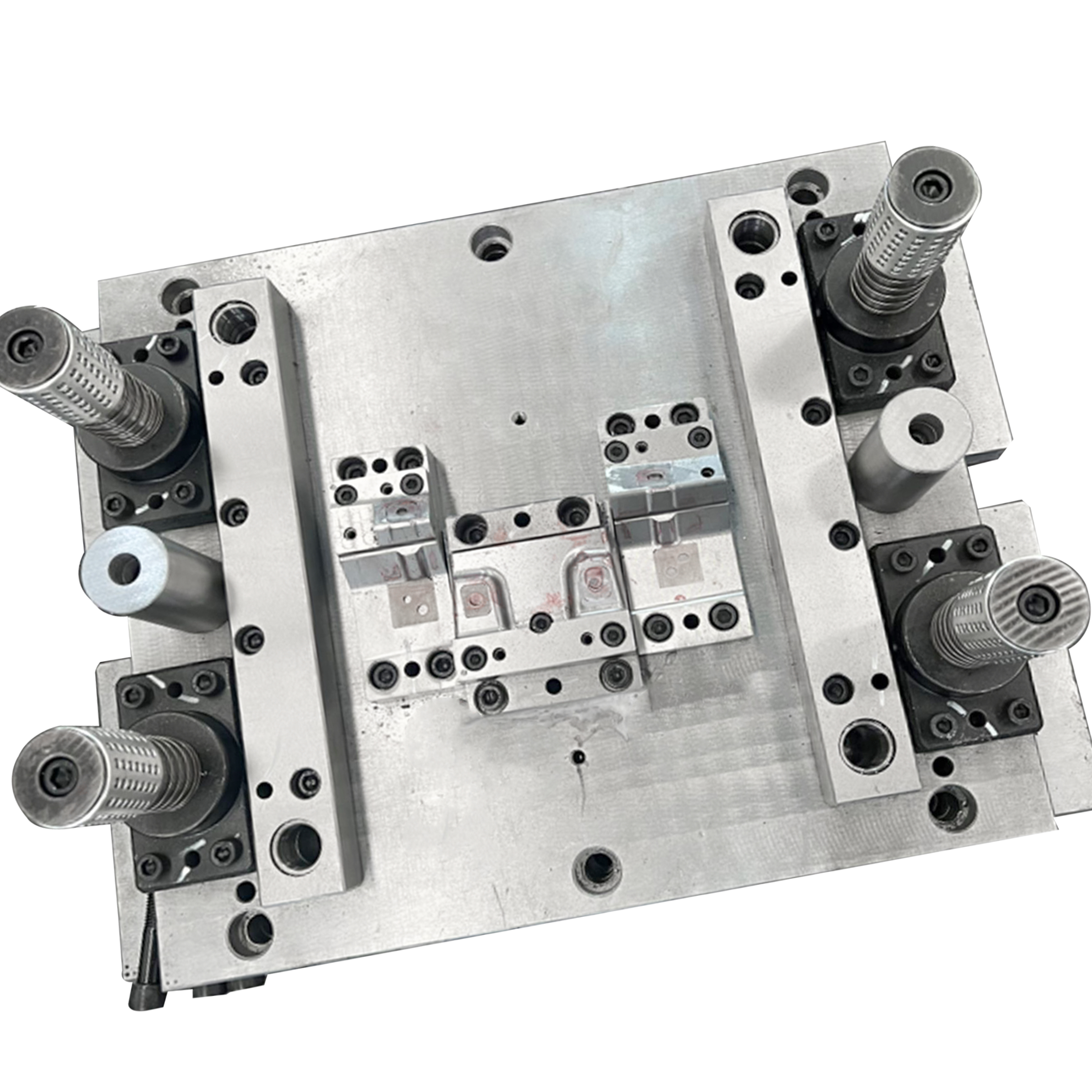
Understand Die Anatomy and Material Choices
Ever wondered what actually goes into a die in manufacturing? Imagine opening up a precision tool and seeing a stack of carefully engineered parts, each one playing a critical role in shaping, cutting, or forming your material. Whether you’re specifying a new metal die or troubleshooting a production issue, knowing the anatomy of a die set—and why material choices matter—gives you the language and insight to make smart decisions.
Core Die Components and Their Functions
Let’s break down the essential die components you’ll find in a typical die set. Each part is designed for a specific purpose, and together they deliver the accuracy and durability your process demands:
- Punch: The moving part that enters the die cavity to cut or form the material.
- Die Cavity (Die Section): The fixed part that receives the punch and defines the final shape of the part.
- Stripper or Pressure Pad: Removes the finished part or scrap from the punch after each cycle.
- Pilots: Precisely position the strip or blank for each operation.
- Guide Pins and Bushings: Ensure perfect alignment between the upper and lower die sets.
- Die Set Plates (Die Shoes): The foundation that holds and supports all other components.
- Heel Blocks: Absorb side thrust and prevent die set misalignment.
- Lifters: Raise parts or scrap out of the die cavity after forming or cutting.
- Springs/Nitrogen Cylinders: Provide force for stripping, pressure pads, or part ejection.
- Sensors: Monitor die operation and detect misfeeds or faults.
- Stock Guides: Direct the material accurately into the die set.
Each die section is carefully engineered to withstand repeated high-pressure cycles, ensuring long-term reliability and consistent part quality.
Guide and Retention Systems: The Backbone of Precision
Alignment is everything in a die set. Guide pins and bushings—sometimes called die set guiding components—are manufactured to extremely tight tolerances (as close as 0.0001 inch) to keep the upper and lower halves of the metal die perfectly aligned. There are two main types of guide pins: friction pins and ball-bearing pins. Ball-bearing guides are now industry standard for high-speed or high-precision applications because they reduce wear and make die section separation easier (The Fabricator).
- Friction Pins: Simple, robust alignment; best for basic applications.
- Ball-Bearing Pins: Smoother operation, easier die set separation, longer life in demanding environments.
Properly selected and maintained guide systems in your die sets mean less downtime, more accurate parts, and longer tool life. Retainers (like punch and button retainers) keep cutting and forming elements securely in place, preventing misalignment and stacking tolerance errors.
Die Steel Selection Factors: Balancing Toughness, Wear, and Cost
Choosing the right die material is crucial for performance and longevity. The best steel die for your application depends on the balance of hardness, toughness, wear resistance, and machinability required:
| Steel Category | Wear Resistance | Toughness | Machinability | Cost Tier | Typical Use |
|---|---|---|---|---|---|
| High-Speed Steel | Excellent | Good | Moderate | High | High-volume cutting/forming dies |
| Cold-Work Tool Steel | Very Good | Good | Good | Medium | Blanking, piercing, forming at room temp |
| Hot-Work Tool Steel | Good | Very Good | Fair | High | Forming at elevated temps |
| Carbon Steel | Fair | Fair | Excellent | Low | Low-cost, low-volume dies |
| Cemented Carbide | Outstanding | Low | Poor | Very High | High-wear, abrasive applications |
When evaluating die material, consider:
- Hardness: Higher hardness increases wear resistance but may reduce toughness.
- Toughness: Prevents brittle fracture under impact or high loads.
- Machinability: Easier machining reduces lead time and cost.
- Cost: Material selection should match the expected die life and production volume.
In most cases, die steel must also resist galling (material transfer between surfaces) and maintain shape after heat treatment. For high-wear or high-precision applications, advanced die sets may use surface coatings (like nitriding or PVD) to further reduce friction, extend tool life, and prevent galling—even if the base die section is made from a tough but less wear-resistant steel.
Understanding die anatomy and material choices is your key to specifying, sourcing, and maintaining die sets that deliver reliable, high-quality results. Up next, we’ll walk through practical die design rules that help you avoid costly mistakes and get your process right from the start.
Apply Practical Die Design Rules That Work
When you’re staring at a complex part print, it’s easy to wonder—where do I start with die design? How do I make sure the die in manufacturing will produce parts that meet spec, with minimal tryouts and headaches? Let’s break down a proven, actionable workflow so you can move from concept to robust die process with confidence.
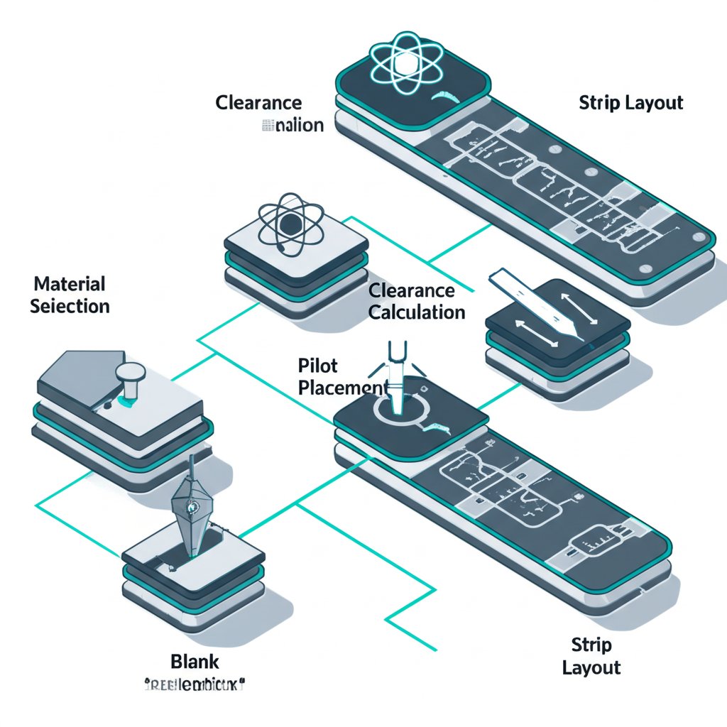
Calculating Clearance and Edge Conditions
-
Define Material, Thickness, and Critical Features
Before you even open your CAD software, study the part material, thickness, and which features are truly critical to quality. Ask: Is this a high-strength steel? Is surface finish vital? Identifying these up front shapes every die design decision. -
Establish Blank Development and Add Feed Carriers
Develop the flat blank shape, considering material flow and feed direction. Design carriers (webs, strips, ties) that move the part through each station. Carriers should be at least twice the material thickness for stability, and their attachment points should allow for easy removal and minimal burrs. -
Select Cutting Clearances Based on Material and Finish
Cutting clearance—the gap between punch and die—must suit the material and thickness. Too tight, and you’ll get tool wear or burrs; too loose, and edges deform. For most steels, clearances range from 5% to 10% of material thickness, but always confirm with your material supplier or process die standards. -
Choose Forming Radii Relative to Thickness and Material
The inside radius of a die form should be no less than the material thickness for ductile materials, and often 1.5–2 times thickness for high-strength grades. This prevents cracking and excessive springback. If a tight corner is unavoidable, consider post-forming operations or special die drawing techniques. -
Plan Pilot Positions for Robust Registration
Pilots are essential for accurate strip positioning at each station. Place pilots after the coil has stabilized—typically after the first or second station—to avoid misfeeds and ensure repeatable die offset.Rule of thumb: Always punch pilots after the material has flattened and the feed is consistent. This minimizes die offset errors and improves punch drawing accuracy.
-
Sequence Piercing Before Forming
Always pierce holes before bending or forming to protect edge quality and maintain tight tolerances. If holes are pierced after forming, distortion and misalignment are likely. This step is critical in any process die or progressive die layout. -
Add Relief and Pressure Pad Strategies to Mitigate Wrinkling
Include relief features and pressure pads to control material flow and prevent wrinkling, especially in deep draw or flange operations. The right die design here can make or break a successful die form. -
Include Stripper Types Appropriate to Burr Direction and Part Release
Stripper plates should match the expected burr direction and ensure clean part ejection. For upward forms, a spring-loaded stripper may be best; for downward forms, use a fixed stripper with proper clearance. -
Define Tolerance Datum Schemes to Contain Stack-Up
Assign datums to the most functionally critical features. Control tolerance stack-up by referencing all stations to these datums, ensuring the final part meets drawing requirements without excessive die adjustment.Balance station forces across the press bed to prevent tipping or uneven wear—a common cause of die offset and inconsistent part quality.
Springback Compensation and Corner Radii
Springback—the tendency of metal to return toward its original shape after forming—can throw off your die drawing if not addressed. Compensate by over-bending in the die design or adjusting the die form radius. For high-strength steels, increase the punch drawing radius and use simulation software to predict final geometry. Always validate with physical tryouts and adjust as needed.
- Draw Beads: Control material flow in deep draws; adjust shape and location to fine-tune draw depth and wall thickness.
- Addendum Geometry: Design the flange and transition zones to avoid sharp transitions that can cause splits or wrinkles.
- Binder Pressure: Maintain consistent pressure to prevent material buckling or tearing during the die process.
Progressive Strip Layout and Station Sequencing
Strip layout is the backbone of progressive die design. The order and placement of each station—blanking, piercing, forming, trimming—directly impacts material usage, part quality, and die longevity. Iterate your layout to minimize scrap, balance forces, and ensure smooth strip movement. Remember, empty stations can be left for future operations or to distribute force more evenly.
For complex parts, use CAE or FEA tools to simulate material flow and predict issues before steel is cut. This digital validation step saves time, reduces costly die tryouts, and helps you achieve a robust process die from the start.
By following these practical die design rules, you’ll reduce risk, streamline die process development, and set yourself up for repeatable, high-quality production. Next, we’ll look at how to size your press and plan for balanced forces—so your carefully designed die performs just as well on the shop floor as it does on paper.
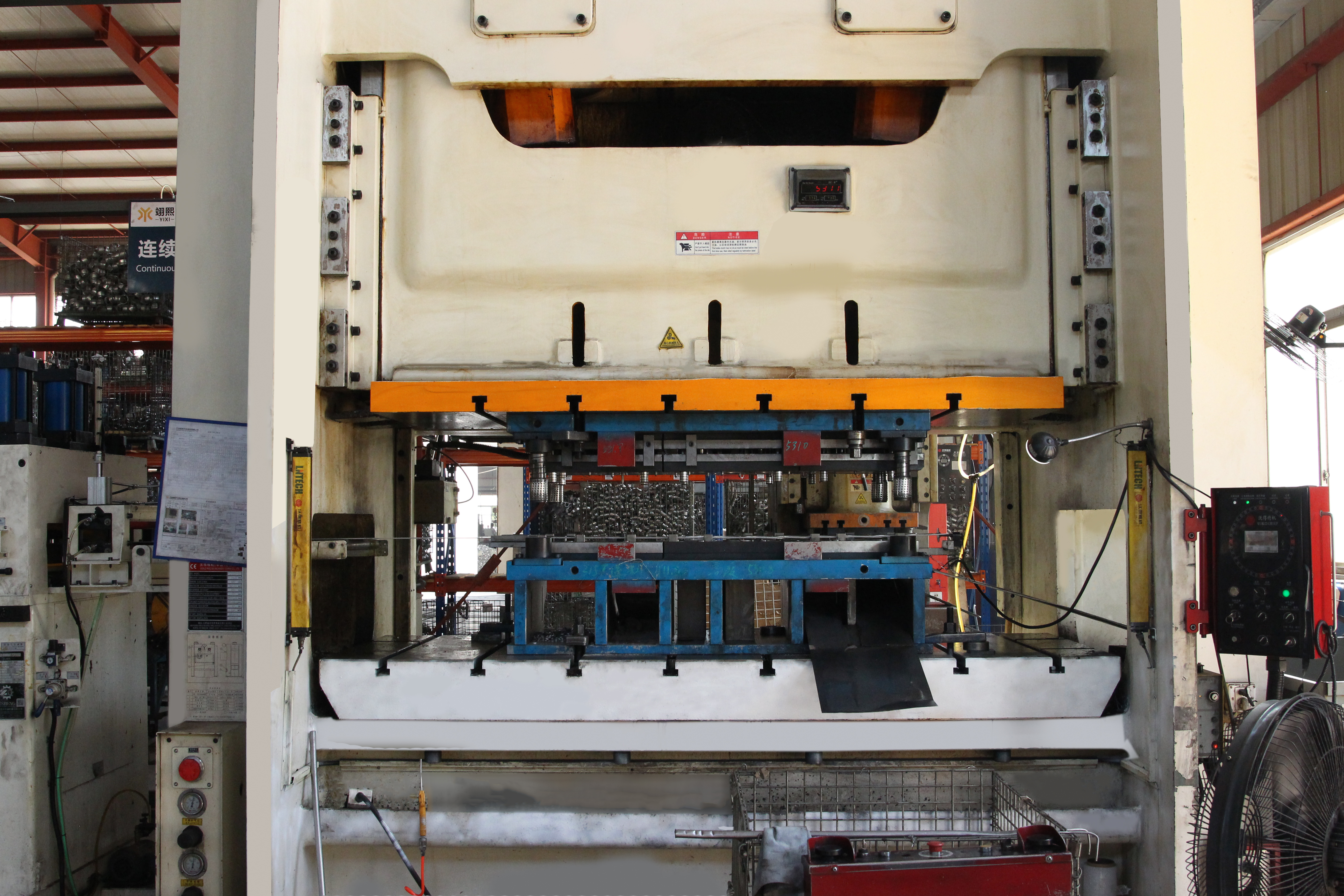
Size the Press and Plan for Balanced Forces
Ever wondered why a perfectly designed die in manufacturing sometimes fails on the shop floor? Often, the culprit isn’t the die—it’s a mismatch between the die press, the die for press, and the forces involved. Getting press sizing right is crucial for uptime, part quality, and die longevity. Let’s walk through a practical, step-by-step approach to sizing your press and ensuring balanced forces for every operation.
Estimating Cutting and Forming Forces
When you set up a new machine die or plan for a production run, the first question is: how much force will the press need? For cutting operations like blanking and piercing, the required force scales directly with the perimeter of the cut and the material’s resistance. The basic equation is:
- Blanking Force (P): P = L × t × S
- L = Perimeter of the cut (mm)
- t = Plate thickness (mm)
- S = Shear resistance of the material (kgf/mm²)
If you don’t know the shear resistance, a common engineering estimate is to use 60% to 75% of the material’s tensile strength. This approach helps you estimate the tonnage needed for your press dies and avoids undersizing the equipment.
| Operation | Primary Force Driver | Tonnage Sensitivity | Notes |
|---|---|---|---|
| Blanking | Perimeter, thickness, shear resistance | High | Use shearing angle to reduce force; check press plate strength |
| Piercing | Hole count, perimeter, material | Medium-High | Multiple holes increase peak force |
| Forming/Bending | Material yield, bend length, geometry | Medium | Springback and friction can affect force |
| Drawing | Draw depth, wall friction, material flow | Very High | May require 2–3× blanking tonnage |
| Embossing/Coining | Detail area, hardness | High | Requires precision and robust machine dies |
Accounting for Material, Thickness, and Operation
Material selection matters—a die for manufacturing aluminum will behave differently than one for high-strength steel. Thicker or harder materials demand more tonnage and a stiffer press plate. For stainless steel, for example, you’ll often need to increase clearance and check for heat buildup during long runs.
Forming and drawing operations are especially sensitive to die press sizing. Deep draws may require two to three times the tonnage of simple blanking, due to material flow and friction. Always review your operation mix—if your die for press combines blanking, forming, and piercing, size for the highest peak load, not just the average.
Choosing the Right Press and Shut Height
Once you’ve estimated your required tonnage, add a safety margin as recommended by your press manufacturer. This protects both the die and the machine die from overload and unexpected material variation. Consider the energy curve of mechanical presses: some lose force at higher speeds or near the bottom of the stroke, so check if your press can deliver the needed force at operating speed.
Always consult your press manufacturer’s guidelines for allowable off-center loading, energy at speed, and shut height compatibility. This ensures your die for manufacturing will perform reliably and safely on the intended equipment.
- Shut Height Compatibility: Confirm the closed height of your die matches the press’s shut height range.
- Bolster Flatness: Ensure the press bed is flat and free of debris to avoid uneven loading.
- Feed Window: Verify there’s enough space for coil or strip feeding—especially for progressive dies.
- Cushion/Blankholder Requirements: For deep draws or embossing, check if a cushion or blankholder is needed for material control.
Imagine running a complex progressive die only to find your machine dies are flexing or the shut height is off by a few millimeters. These small oversights can lead to tool damage, downtime, and inconsistent part quality. Taking time to check these factors up front pays off in smooth, reliable production.
By sizing your press with a conservative, methodical approach—and confirming all practical requirements—you’ll maximize uptime, protect your investment, and get the best results from every die in manufacturing. Next, we’ll guide you through the end-to-end workflow of taking your die from CAD model to finished, production-ready tooling.

Navigate CAD to Finished Die Like a Pro
Ever wondered what happens behind the scenes after you approve a die design? The journey from digital model to a finished die in manufacturing is a meticulous, multi-step process—one that directly impacts cost, lead time, and the quality of your stamped parts. Let’s walk through each phase so you can anticipate challenges, communicate clearly with your supplier, and make smarter decisions for your next project.
From CAD to CAM and Machining: Laying the Foundation
-
CAD Modeling and Design Review
Everything starts with a detailed 3D CAD model. Engineers use CAD software (like SolidWorks or AutoCAD) to define every feature, surface, and tolerance. Early design reviews catch issues that could delay production or cause rework. Precise modeling is the backbone of tool and die manufacturing, as even small errors here can multiply costs downstream. -
CAM Programming and Process Planning
Next, CAM (Computer-Aided Manufacturing) software translates the CAD model into toolpaths for CNC machines. Decisions about roughing, finishing, cutter selection, and machining order are made at this stage—balancing speed, accuracy, and surface finish. Effective CAM programming reduces machining time and tool wear, helping control costs in die manufacturing. -
CNC Milling of Plates and Inserts
CNC milling machines shape die plates, form inserts, and other large features. This step is ideal for removing bulk material and establishing the primary geometry of the die set. For features with tight tolerances or complex contours, advanced 5-axis machining may be used.
EDM, Grinding, Fitting, and Benching: Achieving Precision
-
Wire and Sinker EDM (Electrical Discharge Machining)
EDM technology is a game-changer for die machining. Wire EDM uses a thin wire and electrical sparks to cut intricate shapes, sharp internal corners, and hardened tool steel—all with minimal distortion. Sinker EDM is used for deep cavities and fine details that are impossible with traditional cutters. EDM is especially important in stamping die manufacturing, where precision and repeatability are critical. -
Heat Treatment and Stress Relief
After rough machining, die components often undergo heat treatment to achieve the required hardness and toughness. Stress relief steps are included to prevent warping or cracking during later use. The sequence and parameters are chosen based on the die steel grade and application. -
Precision Grinding
Surface grinding brings parts to their final dimensions and smoothness. Grinding is essential for mating surfaces, guide pins, and shut faces—areas where even a micron of variation can affect die performance. The goal is to achieve the tolerances and finishes required for high-volume production. -
Benching, Stoning, and Polishing
Skilled toolmakers hand-fit and finish critical surfaces, using stones and polishing tools to remove minor imperfections. This hands-on step ensures flawless assembly and optimal material flow during stamping.
Assembly, Tryout, and Debug: Bringing the Die Machine to Life
-
Assembly and Alignment Checks
All components are assembled into the die set. Technicians check for alignment, fit, and smooth operation, using precision indicators and test blocks. Sensors and instrumentation are installed if needed for process monitoring. -
Tryout on Press and Coil Feed
The die machine is mounted in a representative press, often with actual coil feed, to simulate production conditions. Sample parts are stamped, and the die is adjusted as needed to correct for springback, burrs, or misfeeds. -
Dimensional Inspection and Debug Loops
Each part is measured using CMMs (Coordinate Measuring Machines), calipers, and gauges. If parts don’t meet spec, the die returns to the benching or machining phase for adjustment. This cycle repeats until the die consistently produces in-tolerance parts. -
Final Approval and Documentation
Once the die passes all tests, documentation is finalized—including as-built drawings, inspection reports, and maintenance guidelines. Good CAD data management and revision control at this stage ensure future changes or repairs are efficient and accurate.
What Drives Lead Time and Cost in Die Manufacturing?
- Material Hardness: Harder die steels require slower machining and more frequent tool changes.
- EDM Hours: Intricate details or deep cavities increase EDM time in stamping die manufacturing.
- Number of Timing-Critical Features: More precise features mean more setup, checks, and possible rework.
- Sensor Wiring and Instrumentation: Advanced dies with in-die sensors add wiring, setup, and debug time.
- Tryout Cycles: Complex dies may need multiple tryout and debug iterations before sign-off.
Strong CAD data management and revision control are vital—losing track of changes or using outdated models can cause expensive rework and production delays.
By understanding each step in the die manufacturing workflow, you’ll see why complexity, hard materials, and intricate features all impact delivery and cost. Clear communication, robust CAD practices, and a collaborative approach with your tool die making partner will help you navigate the process and achieve the best results. Next, let’s explore how to troubleshoot common die and press issues to keep your production running smoothly.
Troubleshoot Dies and Stabilize Production
When your production line grinds to a halt or rejects pile up, it’s time to ask: Where did things go wrong with your stamping dies? Imagine finding burrs on every part, parts stuck in the die, or sensors tripping for no clear reason. Sounds complex? It doesn’t have to be. With a structured troubleshooting approach, you can diagnose issues in metal stamping dies quickly and keep your die tools—and production—running smoothly.
Eliminate Burring and Galling: Spotting and Solving Edge Defects
| Symptom | Likely Root Causes | Diagnostic Checks | Corrective Actions |
|---|---|---|---|
| Excessive Burr Height | Worn punch/die edges, improper clearance, dull die tools | Inspect edge sharpness, measure clearance, check for wear patterns | Sharpen/replace cutting sections, adjust die clearance, schedule regular maintenance |
| Galling on Punches | Insufficient lubrication, improper die material pairing, surface finish issues | Examine punch surfaces, review lubrication method, check for material transfer | Improve lubrication, consider surface treatments, match die/punch materials appropriately |
| Slug Pulling | Incorrect stripping force, sticky slugs, worn strippers | Watch part ejection, inspect stripper condition, observe slug behavior | Adjust stripping force, clean/replace strippers, use anti-stick coatings |
Stop Misfeeds and Timing Errors: Keeping Your Die Tools in Sync
| Symptom | Likely Root Causes | Diagnostic Checks | Corrective Actions |
|---|---|---|---|
| Misfeeds or Feed Jams | Improper feed pitch, coil not straightened, worn pilots, timing errors | Check feed distance, inspect coil straightness, verify pilot engagement | Adjust feed pitch, service straightener, replace pilots, review feed/pilot timing |
| Pilot Damage | Feed not released at correct time, misaligned die set, worn pilots | Observe pilot action, check die alignment, inspect for wear | Synchronize feed release, realign die set, replace worn pilots |
| Sensor Nuisance Trips | Loose scrap, slug jams, faulty wiring, misaligned sensors | Inspect die for debris, test sensor function, check wiring and placement | Clear debris, secure wiring, recalibrate or reposition sensors |
Extend Die Life and Prevent Premature Wear: Proactive Maintenance for Metal Stamping Dies
| Symptom | Likely Root Causes | Diagnostic Checks | Corrective Actions |
|---|---|---|---|
| Part Distortion/Wrinkling | Improper pressure pad setup, uneven die wear, incorrect forming sequence | Review pressure pad settings, inspect die surfaces, check forming order | Adjust pressure pads, resurface die, revise forming sequence |
| Panel Splits or Cracks | Material defects, sharp radii, excessive forming force, worn die tools | Inspect material batch, measure radii, check force settings, look for tool wear | Switch to qualified material, increase radii, reduce force, sharpen/replace tools |
| Inconsistent Wear Patterns | Poor alignment, uneven press force, improper die clearance | Verify die alignment, check press settings, measure clearances | Realign die, adjust press force, correct clearances |
Preventive Practices: Keep Your Stamping Dies Running Smoothly
- Schedule regular sharpening of cutting sections and punch edges
- Maintain proper land and relief geometry on all die tools
- Set and verify correct stripping force for each operation
- Inspect and clean dies for debris, loose fasteners, and lubrication buildup
- Validate sensor function and wiring before and during production
- Document and track all maintenance and repairs for continuous improvement
"Systematic troubleshooting, supported by data—not just experience—helps you pinpoint root causes and implement fixes that last. Preventive maintenance isn’t just a checklist; it’s your insurance for consistent, high-quality output."
By applying these structured troubleshooting steps and preventive practices, you’ll turn downtime into uptime and keep your metal stamping dies and die tools delivering reliable results. Ready to choose the right stamping die partner and leverage simulation-driven development? Let’s explore how to evaluate a die manufacturer for your next project.

Select a Partner for CAE Driven Stamping Dies
When you’re ready to invest in a new automotive die or launch a high-volume stamping project, the partner you choose can make or break your success. Imagine this: you’ve nailed the design, but your die manufacturer can’t predict springback or optimize material flow—so you’re stuck in endless tryouts, lost time, and ballooning costs. Sounds familiar? That’s why selecting the right partner for your die in manufacturing is about more than just price—it’s about technical depth, simulation capability, and proven reliability.
What to Look for in a Stamping Die Partner
- Engineering Depth: Does the team have experience with complex parts, advanced materials, and tight tolerances?
- CAE Simulation Capabilities: Can they virtually test die geometry, material flow, and springback before cutting steel?
- Tryout and Tooling Efficiency: Will their process minimize physical tryouts, reduce lead time, and control costs?
- Certifications: Are they IATF 16949 or ISO 9001 certified, showing commitment to quality and process control?
- Collaborative DFM Reviews: Will they work with you on design-for-manufacturing (DFM) to catch issues early?
- Industry Reputation: Do they have a track record with global brands and long-term partnerships?
Let’s compare leading die manufacturing companies and see how these factors stack up for your next project.
| Die Manufacturer | CAE Simulation | Certifications | Engineering Support | Tryout Efficiency | Production Scope | Industry Focus | Learn More |
|---|---|---|---|---|---|---|---|
| Shaoyi Metal Technology | Advanced CAE for die geometry & material flow | IATF 16949 | In-depth DFM, structural reviews, formability analysis | Significantly reduced tryout cycles and tooling cost | Prototype to mass production | Automotive, industrial tool die and engineering | Shaoyi Automotive Dies |
| Talan Products | Process optimization, quality analytics | ISO 9001:2015 | Extensive training, continuous improvement | Industry-low defect rates, fast delivery | High-volume stamping | Automotive, consumer, industrial | Talan Products |
| Hatch Stamping | Engineering software, CMM inspection | IATF 16949, ISO 14001 | Hands-on project management | Custom die builds, repair & machining | Progressive, transfer, specialty dies | Automotive, solar, industrial | Hatch Stamping |
CAE Simulation and Formability Analysis Benefits
Why does simulation matter in what is tool and die manufacturing? With advanced CAE tools, you can:
- Virtually try out die designs to predict springback, thinning, and wrinkles before steel is cut (Keysight).
- Optimize die geometry for complex automotive die shapes and high-strength materials.
- Reduce lead time and cost by minimizing physical tryouts and rework.
- Meet tight tolerances and quality standards for even the most demanding industries.
- Quickly adapt to changes in material or process conditions, keeping your supply chain agile.
For example, Shaoyi Metal Technology leverages simulation to streamline everything from blank development to final part inspection, helping you move from prototype to production with confidence and fewer surprises.
From Prototype to Mass Production with Confidence
When evaluating die manufacturers, look for partners who support you at every stage—concept, design, tryout, and production ramp-up. The best tool and die companies will:
- Provide collaborative engineering input early in the process
- Offer transparent documentation and revision control
- Support troubleshooting and continuous improvement after launch
- Demonstrate a clear commitment to quality and safety
Choosing a partner with robust CAE simulation, strong certifications, and a proven track record in industrial tool die and engineering means you’re set up for fewer setbacks and higher yield. Don’t hesitate to request references, review past projects, and ask for sample simulation outputs to gauge a supplier’s capabilities.
"The right die manufacturing partner is not just a vendor—they’re your ally in innovation, risk reduction, and long-term success. Simulation, certification, and collaborative engineering are the hallmarks of leading die manufacturers."
Ready to move forward? Explore more about simulation-led automotive die development at Shaoyi Metal Technology, or use this checklist to compare other die manufacturing companies for your next project. Up next, we’ll turn these insights into an actionable plan so you can execute with confidence from day one.
Turn Insights into an Executable Plan
When you’re ready to move from theory to action, it helps to have a clear, step-by-step checklist. After all, a die is used to shape, cut, and form material with precision—so why not bring the same rigor to your planning process? Whether you’re launching a new product or optimizing existing dies in manufacturing, this actionable guide will help you avoid missed details, reduce costly errors, and set your project up for success.
Actionable Checklist for Your Next Die Project
| Step | Key Actions |
|---|---|
| 1. DFM Readiness | Review part design for manufacturability; confirm material selection, tolerances, and finish requirements. |
| 2. Die Type Selection | Choose the right die architecture—progressive, transfer, single station, or combination—based on volume and complexity. |
| 3. Component Specifications | Define tool and die requirements: punch, die section, stripper, guides, sensors, and die material. |
| 4. Press Sizing & Compatibility | Calculate required tonnage; check shut height, bolster flatness, and feed window for your manufacturing die. |
| 5. Workflow & Process Planning | Map out every step from CAD to CAM, machining, assembly, tryout, and inspection. |
| 6. Inspection & Quality Control | Establish measurement routines, CMM checks, and process documentation for each stage. |
| 7. Maintenance & Upkeep | Develop a preventive maintenance plan—regular inspection, sharpening, alignment, and lubrication. |
| 8. Simulation & Tryout Reduction | Leverage CAE simulation to predict material flow and springback, minimizing physical tryouts and costly rework. For advanced projects or automotive dies, consider partners with IATF 16949 certification and proven simulation expertise. |
Key Takeaways to Share with Your Team
- Clear, sequenced planning is the foundation of every successful manufacturing die project. Don’t skip the basics—checklists help you catch what experience alone might miss (The Fabricator).
- Tool and die definition goes beyond hardware—it’s about process control, preventive maintenance, and a continuous improvement mindset.
- Simulation, certification, and collaboration with expert partners can dramatically reduce tryout cycles and accelerate your timeline.
Accelerate Your Die in Manufacturing Success
- Share this checklist with your engineering, quality, and procurement teams to align on scope and expectations.
- Use the checklist as a template for upcoming projects, adapting it to your specific needs and industry standards.
- If your project requires advanced simulation, certification, or automotive expertise, explore resources like Shaoyi Metal Technology for guidance and proven solutions.
- For vendor-neutral planning, consider developing your own checklist based on your organization’s unique requirements, using the tool and die definition as your guidepost.
Define tool and die requirements early, maintain a disciplined workflow, and leverage expert resources—these are the keys to reliable, cost-effective dies in manufacturing.
Frequently Asked Questions About Die in Manufacturing
1. What is a die in a factory setting?
In a factory, a die is a specialized precision tool used to cut, shape, or form material—such as metal or plastic—into specific parts by applying force with a press. Dies ensure repeatable, accurate production for high-volume manufacturing of components.
2. What are the main types of dies used in manufacturing?
The main types of dies include progressive, transfer, single station (line), compound, and combination dies. Each type is suited for different part complexities, production volumes, and operations like blanking, piercing, forming, or drawing.
3. How do you choose the right die for a manufacturing project?
Choosing the right die depends on part geometry, production volume, required tolerances, material type, and downstream operations. Early design-for-manufacturing reviews and understanding your press capabilities are key to selecting the optimal die type.
4. Why is CAE simulation important in die manufacturing?
CAE (computer-aided engineering) simulation helps predict material flow, springback, and potential defects before the die is built. This reduces physical tryouts, saves costs, and ensures high-quality, reliable production—especially for complex or automotive parts.
5. What should you look for in a die manufacturer or partner?
Look for a die manufacturer with strong engineering expertise, advanced CAE simulation capabilities, relevant certifications (like IATF 16949), efficient tryout processes, and a proven track record in your industry. Collaborative support from design through production ensures the best results.