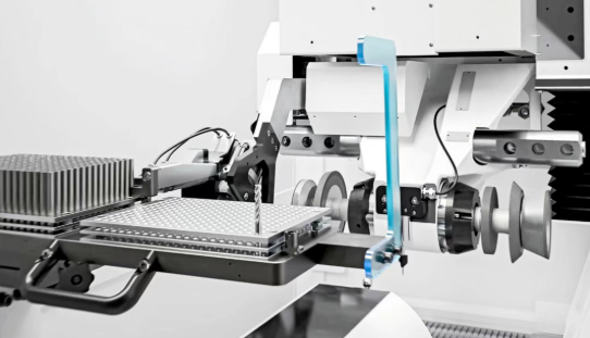
 Small batches, high standards. Our rapid prototyping service makes validation faster and easier —

Understanding Shimming Techniques For Die Repair: The Basics
What Shimming Techniques for Die Repair Actually Mean
When you hear "shimming" in a stamping shop, the term gets thrown around loosely. Some folks mean adjusting the press brake bed to compensate for deflection. Others mean correcting a worn die component. These are fundamentally different operations, and confusing them leads to wasted time and poor results.
So what does shimming actually mean when you're repairing a die? It's a targeted corrective technique applied directly to die components. You're placing precision-thickness material beneath or behind specific tooling elements to restore dimensional accuracy, compensate for wear, or correct height variance between stations. The goal is simple: get the die back to producing parts within tolerance without a full rebuild.
What Shimming Actually Means in Die Repair
Imagine you've just reground a punch or die section. That regrind removed material, so the component now sits slightly lower than it did originally. The gap body between the punch and die has changed. Without correction, your parts come out wrong. Shimming restores that lost height precisely.
The same principle applies when wear accumulates over thousands of press cycles. Die seats develop uneven surfaces. Progressive die stations drift out of alignment with each other. Rather than scrapping expensive tooling, you shim to bring everything back into spec.
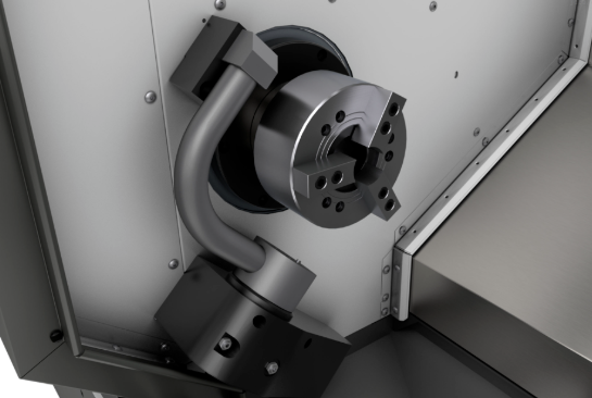
Die-Level vs. Machine-Level Shimming — Why the Difference Matters
Here's where many resources get it wrong. They conflate two completely separate operations:
Bed shimming adjusts the machine to compensate for deflection under load. Die shimming repairs the tooling itself to restore dimensional accuracy. One fixes the press; the other fixes the die.
When you shim a press brake bed, you're counteracting the "canoe effect" where the center deflects more than the ends under tonnage. That's machine compensation. When you shim a die component, you're addressing wear, regrind loss, or manufacturing variance in the tooling itself. Confusing these leads to chasing problems in the wrong place.
For working toolmakers and die technicians, this distinction shapes your entire diagnostic approach. If parts are coming out wrong, you need to know whether the issue lives in the machine or the die before you start adding shims anywhere. The core scenarios where die-level shimming applies include:
- Uneven die seat surfaces from wear or damage
- Height variance between progressive die stations affecting strip progression
- Post-regrind height compensation to restore original shut height
- Correcting manufacturing tolerances in new or rebuilt die sections
Throughout this guide, we'll focus specifically on die-level shimming. You'll learn how to diagnose when it's the right repair path, measure wear accurately, select appropriate shim materials like hardened steel or liquid shim compounds, and execute the procedure correctly. This is practitioner-level content for people who actually work on dies, not a high-level overview for operations managers.
How to Diagnose Whether Shimming Is the Right Repair
You've identified a dimensional problem with your die. Parts are out of spec, or you're seeing inconsistent results across stations. Before reaching for shim stock, you need to answer a critical question: is shimming actually the right fix? Jumping straight to shimming without proper diagnosis often masks deeper problems or creates new ones.
Think of it this way. Shimming compensates for height variance, but it doesn't fix structural damage, restore worn cutting edges, or correct warped die sections. If you shim over a problem that requires regrinding or replacement, you're just delaying the inevitable while producing questionable parts in the meantime.
Measuring Die Height Variance Before Deciding on Shimming
The first step in any die repair decision is quantifying the problem. You can't determine whether shimming is appropriate until you know exactly how much height variance you're dealing with and where it's located.
Work through these diagnostic criteria in sequence:
- Measure the die height variance at multiple points across the die seat using a dial indicator or height gauge. Record the maximum deviation from nominal.
- Check whether the variance falls within your shop's correctable range for shimming. If height loss exceeds your established threshold, shimming alone won't restore proper function.
- Inspect the die seat surface for flatness. A warped or damaged seat surface won't support shims properly and will cause uneven load distribution.
- Determine whether the wear is localized to specific areas or distributed across the entire working surface. Localized wear often indicates a different root cause that shimming won't address.
- Examine the cutting edge geometry. If edges are chipped, cracked, or significantly worn, the die section needs sharpening or replacement regardless of height variance.
- Review the die's repair history. Multiple previous shim interventions may indicate cumulative wear that warrants regrinding or insert replacement instead.
Each of these checkpoints guides you toward the appropriate intervention. Skip one, and you risk choosing the wrong repair path.
Decision Tree — Shimming vs. Regrinding vs. Replacement
Once you've gathered your measurements, map them against this decision framework. The goal is matching the observed condition to the repair that actually solves the problem.
When the die is cast in terms of your repair decision, consider these branching paths:
- If height variance is within correctable range AND the die seat is flat AND cutting edges are serviceable, shimming is appropriate.
- If height variance is within range BUT cutting edges show wear or damage, sharpen or regrind first, then shim to compensate for material removed.
- If height variance exceeds your shop's shimming threshold, regrinding the die section is typically the better path.
- If the die seat surface shows warping, pitting, or structural damage, the section likely needs replacement or regeneration rather than shimming.
- If you observe deep cracks propagating through the die body, replacement becomes necessary since repairs may compromise safe operation.
The table below summarizes common conditions and their recommended repair paths for stamping tool repair scenarios:
| Condition Observed | Measurement Method | Recommended Repair Path |
|---|---|---|
| Minor height loss within tolerance range | Dial indicator at multiple die seat points | Shimming |
| Height loss with dull cutting edges | Height gauge plus visual edge inspection | Regrind first, then shim |
| Height variance exceeding shop threshold | Height gauge comparison to nominal spec | Regrinding or insert replacement |
| Uneven die seat surface or warping | Surface plate and feeler gauge check | Section replacement or regeneration |
| Localized pitting or chipping on working surface | Visual inspection plus depth measurement | Welding repair or insert replacement |
| Deep cracks in die body or core | Dye penetrant or magnetic particle testing | Die replacement |
| Cumulative shim stack approaching maximum | Review of tooling maintenance records | Regrind to reset baseline |
Notice that shimming appears as the recommended path only when specific conditions are met. It's not a universal fix. Effective die repair and maintenance requires matching the intervention to the actual problem, not defaulting to the quickest option.
Your shop should establish specific threshold values based on your die designs, part tolerances, and quality requirements. What's acceptable for a rough blanking operation differs significantly from a precision progressive die producing automotive components. Reference your toolmaker standards or work with your engineering team to define these limits.
With the diagnostic framework established, the next step is understanding exactly how to measure die wear accurately so you can select the correct shim thickness.
Measuring Die Wear to Select the Right Shim Thickness
You've determined that shimming is the right repair path. Now comes the critical step that separates a successful correction from a guessing game: accurate measurement. Every micro adjustment you make with shims depends entirely on how precisely you quantify the wear or height variance you're correcting. Get the measurement wrong, and your shim selection will be wrong too.
Sounds straightforward? In practice, many technicians skip steps or take shortcuts that compromise accuracy. The result is parts that still don't meet spec, or worse, a die that performs inconsistently across production runs. Let's walk through the measurement methodology that actually works.
Using Feeler Gauges and Dial Indicators for Die Wear Measurement
Three primary tools handle die wear measurement: feeler gauges, dial indicators, and height gauges. Each serves a specific purpose in your tooling maintenance workflow.
Dial indicators are your go-to for measuring height variance across die seats. These instruments use a plunger mechanism that transfers position changes to a needle on a graduated dial face. When you're checking die height, you'll typically mount the indicator on a stand or magnetic base to keep it stable throughout the measurement process. The needle moves in response to surface variations, giving you precise readings of how much the die seat has worn or shifted.
Feeler gauges work differently. These thin metal blades of known thickness let you check gaps between surfaces directly. When assessing die seat flatness or checking clearances, you slide progressively thicker blades into the gap until you find one that fits snugly. This tells you the exact gap dimension at that point.
Height gauges provide absolute measurements from a reference surface. You'll use these to compare die component heights against nominal specifications or to measure the total height of a die section before and after shimming.
Here's the measurement procedure you should follow for consistent, reliable results:
- Clean the die seat thoroughly. Remove all debris, lubricant residue, and metal particles. Any contamination between the measuring instrument and the die surface will skew your readings.
- Place the die on a surface plate or other verified flat reference surface. This establishes your measurement baseline.
- Zero your height gauge or dial indicator against the reference surface. For dial indicators, rotate the bezel to align the zero mark with the needle position.
- Measure at multiple points across the die seat. For single-stage dies, a minimum of four points (corners) plus the center typically suffices. Progressive dies require measurements at each station.
- Record each reading systematically. Note the location and value for every measurement point.
- Calculate the variance by comparing readings to nominal specifications or to each other. The difference between your highest and lowest readings indicates total variance across the surface.
- Determine required shim thickness based on the variance measurements and your target correction.
Calculating Required Shim Thickness from Variance Measurements
Once you've recorded your measurements, calculating shim thickness becomes a matter of simple arithmetic. But the calculation method depends on what you're correcting.
For uniform height loss across the entire die seat, your shim thickness equals the difference between nominal height and measured height. If your die section should be 2.000 inches tall and measures 1.995 inches, you need a 0.005-inch shim.
For uneven wear, the calculation gets more nuanced. You'll need to decide whether to shim to the highest point, the lowest point, or an average. In most cases, shimming to restore the nominal height at the critical working area makes the most sense. This might mean accepting slight variance at non-critical locations.
Measurement point density matters significantly when you're working with progressive dies versus single-stage dies. A single-stage die might need only five measurement points to characterize the die seat condition. A progressive die with eight stations could require 40 or more measurements to capture the height relationship between all stations accurately. Why? Because shimming one station affects how the strip progresses to adjacent stations. You need the complete picture before making corrections.
The tolerance of your shim thickness directly determines the dimensional accuracy of your finished parts. A shim that's 0.002 inches off from your calculated requirement translates to 0.002 inches of error in every part the die produces.
This relationship between measurement precision and part quality is why experienced toolmakers invest time in careful measurement rather than estimating shim thickness by feel. When you're producing thousands of parts per shift, even small measurement errors compound into significant quality issues and scrap rates.
Digital dial indicators can simplify this process by displaying readings numerically rather than requiring you to interpret needle positions on a graduated dial. They also often include data output features that let you record measurements directly to a computer or quality management system. For shops focused on documentation and traceability, this capability streamlines the tooling maintenance workflow considerably.
With accurate measurements in hand, you're ready to select the appropriate shim material for your specific application and tonnage requirements.
Shim Material Selection
You've measured your die wear and calculated the required shim thickness. Now comes a decision that many technicians overlook: what material should that shim be made from? Grabbing whatever's handy in the toolbox might work for a quick fix, but for stamping die maintenance that holds up under production tonnage, material selection matters.
Different shim materials behave very differently under load. Some compress. Some corrode. Some distribute force evenly while others create stress concentrations. Choosing wrong means your carefully calculated correction won't perform as expected, and you'll be back at the die sooner than planned.
The table below breaks down the key properties that matter for die repair decisions:
| Material | Hardness Range | Compressibility | Corrosion Resistance | Best Use Case | Limitations |
|---|---|---|---|---|---|
| Hardened Tool Steel | 58-62 HRC | Virtually none | Low to moderate | High-tonnage applications with tight tolerances | Difficult to cut on-site; requires rust prevention |
| Stainless Steel (304/316) | Up to 1,275 MPa tensile (full-hard) | Virtually none | Excellent | Corrosive environments; long-term installations | Higher cost than carbon steel |
| Brass | Soft to medium | Slight | Good (water, fuel, mild acids) | Softer die materials; vibration dampening | Not suitable for highest tonnage applications |
| Polymer/Adhesive | Variable | Moderate to high | Excellent | Light-duty corrections; temporary fixes | Compresses under heavy load; degrades over time |
| Laminated Metal | Matches base metal | None per layer | Depends on material | Fine-tuning thickness on-site | Stacking limits apply |
Hardened Tool Steel Shims — When High Tonnage Demands Rigid Support
When you're running a progressive die at 200 tons or more, there's really only one material category that makes sense: hardened tool steel or stainless steel. These materials share a critical property that separates them from everything else—they're essentially incompressible under the loads you'll encounter in stamping operations.
Why does incompressibility matter so much? Imagine you've calculated a 0.10 mm shim correction. With a metal shim, that 0.10 mm stays 0.10 mm whether you're running at 50 tons or 500 tons. The compensation you designed is the compensation you get. With compressible materials, your actual correction varies with tonnage, making consistent part quality nearly impossible to achieve.
Stainless steel shim stock in grades like 304 and 316 offers an additional advantage: corrosion resistance. Full-hard 304 stainless delivers tensile strength up to 1,275 MPa while resisting oxidation and chemical exposure far better than carbon steel alternatives. For dies exposed to coolants, lubricants, or humid shop environments, this durability translates to longer service life between shim replacements.
Industrial shim stock typically comes in standardized thicknesses ranging from 0.05 mm up to 6.00 mm, with tighter tolerances at thinner gauges. At 0.127 mm thickness, for example, precision-rolled stainless steel maintains tolerances of approximately ±0.0127 mm. This level of consistency means your calculated correction translates directly to actual die performance.
One practical consideration: hardened steel shims are difficult to cut or modify on the shop floor. You'll typically need to order pre-cut sizes or use laser cutting, waterjet, or CNC punching for custom shapes. Plan ahead rather than expecting to fabricate these on the fly.
Brass and Polymer Shims — Compliance, Corrosion Resistance, and Temporary Fixes
Not every shimming application demands maximum rigidity. Sometimes a bit of compliance actually helps, and sometimes you need a quick temporary correction while waiting for proper materials to arrive.
Brass shim stock occupies an interesting middle ground. As a copper-zinc alloy, it's softer than steel but still maintains dimensional stability under moderate loads. Brass shims are easy to cut, punch, or modify on-site, making them practical for rapid prototyping or situations where you need to fabricate a custom shape quickly. Typical thicknesses range from 0.05 mm to 1.0 mm.
Where brass really shines is in applications requiring slight compliance or vibration dampening. The material's ductility allows it to conform slightly to surface irregularities, which can improve load distribution in some scenarios. It also resists corrosion from water, fuel, and mildly acidic environments better than plain carbon steel.
However, brass has clear limitations. For high-tonnage stamping operations with tight tolerances, it's simply not rigid enough. The slight compressibility that helps with vibration dampening becomes a liability when you need micron-level precision.
Polymer and adhesive shims represent the opposite end of the spectrum. These include products like adhesive shim tape and liquid shim compounds that cure in place. They're convenient—you can apply them quickly without precise cutting—but they come with significant trade-offs.
The fundamental problem with polymer-based shims is compressibility. Under heavy tonnage, these materials compress, meaning your actual correction is less than the theoretical thickness you applied. Paper shims, often used as a quick fix, suffer the same issue. Ordinary printer paper compresses under load and absorbs oils and coolants, causing it to swell and eventually decay.
Liquid shim products and liquid plastic coating compounds can fill irregular gaps that solid shims can't address. They're useful for temporary corrections or for applications where you need to conform to an uneven surface. But for production stamping dies, treat them as stopgap measures rather than permanent solutions.
One specialized option worth knowing about: laminated shims. These consist of multiple bonded metal foils, each as thin as 0.05 mm. You can peel off layers with a blade to fine-tune thickness on-site, combining the rigidity of metal with the adjustability you'd normally only get from stacking multiple shims. For technicians who need to dial in precise corrections without maintaining an inventory of every possible thickness, laminated shims offer a practical middle path.
Keep in mind that excessive stacking—whether with laminated shims or individual layers—introduces its own problems. More than four shim layers can reduce stability and introduce flex or vibration under load. When you find yourself stacking beyond that limit, it's usually a sign that regrinding or other intervention is overdue.
With your shim material selected based on tonnage requirements and environmental conditions, the next step is executing the actual shimming procedure correctly—starting with surface preparation that many technicians underestimate.
Step-by-Step Shimming Procedure for Single-Stage Dies
You've diagnosed the problem, measured the wear, and selected your shim material. Now it's time to actually install the shim. This is where many technicians rush through the process and wonder why their correction didn't hold up after a few thousand press cycles. The difference between a shimming job that lasts and one that fails within a week often comes down to execution details that seem minor but aren't.
What follows is the complete procedural sequence for shimming single-stage dies. Each step builds on the previous one, and skipping any of them introduces risk. Whether you're compensating for post-regrind height loss or correcting accumulated wear, this workflow applies.
- Prepare the die seat surface by cleaning and verifying flatness.
- Size and cut the shim to match die seat geometry precisely.
- Position the shim with correct placement sequence and orientation.
- Secure the die using proper fastener torque specifications.
- Run initial press cycles to seat the shim stack.
- Re-torque all fasteners after the settling period.
- Verify the correction with post-shimming measurements.
- Document the repair for maintenance records.
Let's break down each step so you understand not just what to do, but why it matters.
Surface Preparation — Why a Clean, Flat Die Seat Is Non-Negotiable
Imagine placing a precision-ground 0.10 mm shim on a die seat contaminated with a 0.05 mm layer of hardened lubricant residue. Your actual correction is now somewhere between 0.10 mm and 0.15 mm depending on where the contamination sits. Worse, that contamination will compress unevenly under tonnage, creating localized stress points that can damage both the shim and the die seat over time.
Surface preparation isn't optional. Under tens of tons of press force, even a speck of metal dust or a smear of hardened oil acts as a random rigid point. This ruins your precision calculations and can leave permanent dents in the die base. The foundation of micron-level shimming tolerates no debris.
Here's how to prepare the surface properly:
- Remove the die from the press and place it on a clean work surface.
- Use industrial alcohol or acetone with lint-free nonwoven cloth to clean the die holder grooves and die bottom thoroughly. Don't just wipe casually with a shop rag.
- Remove all traces of old tape, oil, crystallized coolant, and any previous shim adhesive residue.
- Inspect for burrs or raised areas. If you find any, dress them gently with an ultra-fine oilstone (1000 grit minimum) without altering the original flatness.
- Perform the fingernail test: close your eyes and lightly run your fingernail across the cleaned surface. Human touch is remarkably sensitive. If you feel any drag or graininess, the surface isn't ready.
After cleaning, verify flatness using a surface plate and feeler gauge. Place the die seat face-down on the surface plate and check for gaps at multiple points. Any gap exceeding your shim thickness tolerance indicates a flatness problem that shimming alone won't solve. A warped die seat needs machining or replacement before you proceed.
Once the surface passes both cleanliness and flatness checks, you're ready to size your shim.
Shim Sizing, Placement, and Orientation
Your shim needs to match the die seat geometry closely. A shim that's too small concentrates load on a reduced area, potentially causing localized deformation. A shim that overhangs the die seat creates unsupported edges that can bend or break under cycling.
For sizing, trace the die seat footprint onto your shim stock or use the die seat dimensions from your tooling documentation. Cut the shim slightly smaller than the seat perimeter—typically 1-2 mm inset from all edges—to ensure it sits fully supported without overhang. If your die seat has bolt holes or locating features, transfer those to the shim and cut clearance holes accordingly.
Placement orientation matters when you're using multiple shims or correcting uneven wear. If you're shimming to correct a tilt rather than uniform height loss, position the thicker correction where the measurement showed the greatest deficit. Mark the shim orientation before installation so you can replicate the setup if needed later.
When stacking multiple shims, keep the total stack to four layers or fewer. Beyond that threshold, the stack loses rigidity and can introduce flex or vibration under load. If your required correction exceeds what four layers can provide, that's a signal to consider regrinding instead.
Fastener Torque and Re-Torquing After Shimming
Here's where many shimming jobs fail. You've done everything right up to this point, but if you don't secure the die correctly, the shim will shift, compress unevenly, or work loose during production.
The tightening sequence matters as much as the torque value itself. If you tighten both ends first, the die rests like a tent over the shim stack, leaving the center suspended. Once press tonnage hits, the die deforms abruptly. This "tent effect" is a common cause of shimming failures and can damage precision die seats.
Follow the center-outward tightening principle:
- Finger-tighten all fasteners to establish initial contact.
- Begin with the fastener closest to the center of the shim stack. Tighten it to approximately 50% of final torque.
- Move to the fastener directly opposite and repeat.
- Continue alternating outward toward the ends, bringing each fastener to 50% torque.
- Repeat the sequence, this time bringing each fastener to full torque specification.
For torque values, reference your toolmaker's specifications or your shop's established standards for the fastener grade and size you're using. Fastener torque depends on bolt grade, thread pitch, and whether threads are lubricated or dry. A lubricated fastener requires less torque to achieve the same clamping force—typically 20-25% less than dry specifications. Using dry torque values on lubricated threads risks over-tightening and thread damage.
Offset bolts play a specific role in securing shim stacks. These fasteners, positioned at an angle or offset from the primary clamping bolts, provide lateral stability that prevents shim migration under the cyclic loading of press operation. If your die design includes offset bolt positions, don't skip them even if the primary fasteners feel secure.
After initial torquing, run 3-5 low-tonnage press cycles. This seat-in run expels micro air pockets between shim layers and allows metal shims to reach their final stabilized thickness under pressure. You can use scrap material for shallow test bends during this settling period.
After the initial press cycles, re-torque all fasteners to specification. This step is commonly skipped and is a leading cause of shim-related failures in production.
The settling process compresses any remaining air gaps and allows the shim stack to conform fully to the die seat. Fasteners that were at proper torque before settling will now be slightly loose. Re-torquing restores the designed clamping force and ensures the correction holds through production runs.
Verification and Documentation
Don't assume your shimming worked just because the die closes properly. Verify the correction with the same measurement methodology you used during diagnosis. Take height readings at the same points you measured before shimming and compare them to your target values.
If measurements show the correction is within tolerance, you're ready for production trials. If not, you'll need to adjust—either adding shim thickness if you're still short, or removing material if you overcorrected. This is why starting with 50% of your calculated shim thickness and working up is safer than installing the full correction immediately.
Finally, document everything. Record the die ID, the pre-shim measurements, shim material and thickness used, post-shim measurements, fastener torque applied, and the date. This documentation serves multiple purposes: it creates a baseline for future maintenance decisions, helps identify wear trends over time, and ensures any technician can replicate or adjust the setup later.
For shops running progressive dies, the shimming process introduces additional complexity. Station-to-station height relationships and strip progression requirements demand a different approach than single-stage tooling.
Progressive Die Shimming
Everything changes when you move from single-stage dies to progressive tooling. The shimming principles remain the same, but the stakes multiply with every station. Shim one station incorrectly, and you don't just affect that operation—you potentially throw off every downstream forming step and compromise the entire strip progression.
Why does this matter so much? In a progressive die, the metal strip advances through multiple stations in sequence. Each station performs a specific operation—punching a pilot hole, forming a feature, trimming an edge. The strip must maintain precise registration throughout this journey. If station heights vary beyond tolerance, the strip doesn't sit flat where it needs to, pilots don't engage correctly, and part geometry suffers across multiple features simultaneously.
Why Station Height Consistency Is Critical in Progressive Dies
Imagine a ten-station progressive die producing an automotive bracket. Station one punches pilot holes. Station three draws a shallow cup. Station seven bends a flange. If station three sits 0.05 mm lower than designed, the draw depth changes. That change affects how the strip feeds into station four. By station seven, the cumulative effect might mean your bend angle is off by two degrees.
This cascading effect is what makes progressive die shimming fundamentally different from single-stage work. Progressive die strips must maintain constant pitch—the distance between station centerlines—throughout the entire forming sequence. Height variance at any station disrupts this relationship.
The timing of a progressive die is critical. As experienced toolmakers note, any time you grind a forming section, you need to keep a precise record of the amount ground off and the amount shimmed. Overshimming one station to solve a local problem often creates a different problem elsewhere. For example, overshimming a draw punch to coin the top surface flat might prevent a downstream bending station from fully closing, resulting in an open bend angle.
Strip carriers add another layer of complexity. Many progressive dies use stretch webs—extra loops of material that deform as the metal is formed—to maintain equal distance between stations during drawing operations. If your shimming correction changes how the strip sits vertically during forming, you affect how these carriers function. The result can be distorted pilot holes, mismatched cuts, or poor part location across multiple stations.
Shimming Sequence and Tolerance Stack-Up Across Multiple Stations
When shimming a progressive die, you can't just address each station in isolation. The sequence matters, and so does understanding how individual tolerances combine across the entire die.
Tolerance stackup describes how small variations at individual stations combine along the dimension chain, potentially leading to larger deviations in the final part. In a worst-case scenario, if each of eight stations contributes 0.02 mm of variance, your total stackup could reach 0.16 mm—enough to push parts out of specification even when each individual station appears acceptable.
Statistical approaches offer a less conservative estimate. The root sum square method assumes independent normal distributions, typically yielding a total variation significantly lower than worst-case summation. But for critical applications, many shops still use worst-case analysis to guarantee compliance.
Here's the progressive die shimming sequence that minimizes stackup risk:
- Measure all stations before making any corrections. Record height readings at each station relative to a common datum—typically the die shoe or a verified reference surface.
- Identify the pilot station and establish it as your reference point. The pilot station controls strip registration for all downstream operations, so its height relationship to other stations is foundational.
- Shim the pilot station first if it requires correction. Verify that pilots engage the strip correctly after shimming before proceeding.
- Work outward from the pilot station, addressing adjacent stations in sequence. This maintains the critical pitch relationship as you progress through the die.
- For each station, calculate the required shim thickness based on both the absolute height variance and the relative height to adjacent stations.
- After shimming each station, verify strip progression by running test cycles with scrap material. Check that the strip feeds smoothly and pilots engage without forcing.
- Re-measure all stations after completing corrections. Confirm that the station-to-station height relationships fall within your tolerance window.
- Document the complete shim configuration—every station, every shim thickness, every measurement—for future reference.
One critical point: before shimming or grinding die sections, verify that the press itself is adjusted to proper shut height. Perform lead check readings on your stop blocks rather than relying on the press counter. If the ram isn't coming down the proper distance, or isn't coming down parallel, you'll chase shimming corrections that don't address the actual problem.
Hard marks on the strip can tell you a lot about die timing and shut height adjustment. If you see hard marks—shiny areas where metal was severely squeezed between mating die surfaces—on one end of the strip but not the other, the press ram may have a parallelism problem that no amount of shimming will fix.
CNC vs. Manual Press Considerations
The machine running your progressive die affects how you approach shimming corrections. CNC press brakes and modern servo presses include their own compensation capabilities—automatic adjustments for deflection, thermal growth, and tonnage variation. Manual machines don't.
When working with CNC equipment, your die-level shimming must account for what the machine is already compensating. If the press automatically adjusts for bed deflection, adding shims to counteract that same deflection creates an overcorrection. You end up fighting the machine's own compensation system.
Before shimming a die that runs on CNC equipment, review the machine's compensation settings. Understand what automatic adjustments are active and how they affect shut height at different positions across the bed. Your shimming strategy should complement the machine's capabilities, not duplicate or contradict them.
Manual machines require more aggressive die-level shimming because they lack automatic compensation. The full burden of maintaining dimensional accuracy falls on the tooling itself. This typically means tighter tolerances on shim selection and more frequent verification measurements during production runs.
For shops running the same progressive die on multiple machines—some CNC, some manual—maintain separate shim configurations for each setup. What works perfectly on a compensated CNC press may produce out-of-spec parts on a manual machine, and vice versa.
With progressive die shimming complete and verified, the final piece of the puzzle is documentation. Tracking what you've done—and how the die responds over time—transforms shimming from a reactive repair into a predictive maintenance tool.
Documenting Shimming Repairs for Predictive Maintenance
You've completed the shimming procedure, verified your measurements, and the die is back in production. Job done, right? Not quite. Without proper documentation, you've just performed a repair that exists only in your memory. The next technician who works on this die—or you, six months from now—will have no idea what corrections were made, why they were made, or how the die has responded over time.
Think of shimming documentation as a precise home inspection for your tooling. Just as a thorough inspection creates a baseline record of a property's condition, your shim log creates a traceable history of die wear and correction. This record transforms individual repairs into actionable data that drives smarter maintenance decisions.
What to Record in a Shimming Repair Log
Effective documentation captures everything needed to understand, replicate, or adjust the shimming intervention. Skip a field, and you create gaps that force future technicians to guess—or worse, start from scratch.
Every shimming repair log should include these data fields:
- Die ID and part number produced
- Station number (for progressive dies) or component location
- Pre-shim measurement at each correction point
- Shim material used (tool steel, brass, polymer, etc.)
- Shim thickness installed
- Post-shim measurement confirming the correction
- Fastener torque applied during installation
- Technician name or ID
- Date of repair
- Total press hits since last regrind or major service
Why does each field matter? The pre-shim and post-shim measurements prove the correction worked. The shim material tells you whether the fix is permanent or temporary. The technician and date create accountability and allow follow-up questions. The hit count connects wear to production volume, revealing how quickly the die degrades under actual operating conditions.
The table below shows a sample shim log structure you can adapt for your shop's needs:
| Field | Example Entry | Purpose |
|---|---|---|
| Die ID | D-2847 | Unique identifier for traceability |
| Station Number | Station 4 (draw) | Locates the correction within progressive dies |
| Pre-Shim Height | 1.995 in | Documents the wear condition before repair |
| Shim Material | Hardened tool steel | Indicates permanence and load capacity |
| Shim Thickness | 0.005 in | Records the exact correction applied |
| Post-Shim Height | 2.000 in | Confirms correction achieved target |
| Fastener Torque | 45 ft-lb (dry) | Ensures consistent clamping across repairs |
| Technician | J. Martinez | Creates accountability and knowledge transfer |
| Date | 2026-02-15 | Establishes timeline for wear tracking |
| Hits Since Regrind | 127,000 | Correlates wear to production volume |
Leading manufacturers treat maintenance ledgers as core assets for long-term die management. Recording usage time, maintenance content, and replaced parts enables easy traceability and data-driven decisions about when to escalate from shimming to more significant interventions.
Using Cumulative Shim Stack Growth as a Wear Indicator
Here's where documentation becomes genuinely powerful. Individual shim records are useful. Cumulative shim stack data over time is transformative.
When you track total shim thickness added to a die section across multiple interventions, you're directly measuring how much material the die has lost since its last regrind or rebuild. A die that started at nominal height and now carries 0.015 inches of shims has worn 0.015 inches. That's not an estimate—it's a precise measurement of cumulative degradation.
This cumulative thickness functions as a leading indicator in a predictive maintenance strategy. Instead of waiting for parts to go out of spec or for the die to fail catastrophically, you can establish thresholds that trigger proactive intervention. When the shim stack reaches your defined limit, you know it's time to regrind the die section or replace the insert—before quality suffers.
Cumulative shim stack thickness is a direct proxy for total die wear since last regrind. Track it, and you'll know when shimming is no longer sufficient.
What threshold should trigger escalation? That depends entirely on your specific situation. Factors include the die's original design tolerances, the part quality requirements you're producing to, the material being stamped, and your shop's risk tolerance. A die producing safety-critical automotive components demands tighter thresholds than one stamping decorative trim pieces.
Rather than adopting arbitrary numbers, work with your engineering team to establish thresholds based on your actual quality requirements. Review historical data from dies that eventually required regrinding—how much total shim thickness had accumulated before quality degraded? That empirical baseline becomes your shop-specific trigger point.
The proactive maintenance approach consistently outperforms reactive strategies. Research shows that fully reactive maintenance costs 25-30% more than preventive approaches, with emergency repairs running two to three times the cost of planned work. Documentation that enables prediction pays for itself many times over.
For shops managing dozens or hundreds of dies, consider integrating shim logs into your CMMS (Computerized Maintenance Management System). Tag entries with standardized keywords—die number, failure mode, correction type—so the data becomes searchable and analyzable. Over time, patterns emerge: certain die designs wear faster, specific materials cause accelerated degradation, particular stations in progressive dies consistently need more frequent shimming.
These patterns inform not just maintenance scheduling but also die design improvements, material selection decisions, and process optimization. What starts as a simple repair log evolves into a strategic intelligence asset.
With documentation systems in place, you've built the foundation for treating shimming as part of a broader die maintenance strategy—one that extends tool life, maintains part quality, and reduces total cost of ownership.
Putting Shimming Techniques Into a Broader Die Maintenance Strategy
Shimming isn't just a quick fix. When done right, it's a precision intervention that protects your investment in tooling and keeps production running within spec. But here's the bigger picture: shimming works best when it's part of a systematic approach to die maintenance rather than a standalone repair.
The techniques covered throughout this guide share a common thread. Accurate diagnosis prevents wasted effort. Precise measurement determines shim selection. Proper material choice ensures the correction holds under tonnage. Correct installation procedure keeps everything stable through production cycles. And documentation transforms individual repairs into predictive intelligence.
Connecting Shimming Practice to Long-Term Die Performance
Every shimming intervention you perform is really about one thing: maintaining dimensional accuracy. The quality of your stamped parts depends directly on how well your dies hold tolerance. As industry experts note, the quality of your stamped part depends on the quality of your die, and proactive maintenance is the key to protecting that quality.
What makes shimming particularly valuable is its role in extending die service life. Rather than scrapping expensive tooling when wear accumulates, you restore function incrementally. Each properly executed shim correction buys additional production cycles before more significant intervention becomes necessary.
The connection between shimming and die longevity runs deeper than simple height compensation. When you track cumulative shim stack growth, you're building a wear profile for each die. That profile tells you how the die degrades under your specific production conditions. Over time, this data reveals which dies need more frequent attention, which materials wear faster, and when regrinding becomes more cost-effective than continued shimming.
Dies engineered with tight tolerances and verified through CAE simulation provide a more predictable baseline for shimming interventions. When the original tooling is manufactured to exacting standards, wear patterns develop more uniformly. Uniform wear means your measurements are more reliable, your shim calculations are more accurate, and your corrections hold longer. For shops evaluating their stamping die tooling strategy, exploring precision-engineered stamping die solutions from suppliers like Shaoyi can establish that predictable foundation.
When to Shim, When to Regrind, and When to Replace — Final Guidance
The decision framework matters as much as the technique itself. Shimming is appropriate when height variance falls within correctable range, die seats remain flat, and cutting edges stay serviceable. When cumulative shim stack approaches your shop's threshold, regrinding resets the baseline. When structural damage or deep cracks appear, replacement becomes the only safe path.
For automotive stamping operations, these decisions carry additional weight. IATF 16949 certification standards emphasize defect prevention, reduction of variation, and documented evidence of continuous improvement. Your shimming practices either support those goals or undermine them. Proper technique, accurate documentation, and data-driven escalation decisions align directly with the quality management principles that automotive OEMs require.
Here are the key takeaways from this guide:
- Die-level shimming repairs tooling; bed shimming compensates for machine deflection. Know which problem you're solving before adding shims.
- Diagnosis comes before correction. Measure height variance, check die seat flatness, and inspect cutting edges before deciding shimming is appropriate.
- Measurement accuracy determines shim selection accuracy. Use dial indicators and height gauges systematically, and record readings at multiple points.
- Material selection matters under tonnage. Hardened tool steel for high-load applications; brass or polymer only for light-duty or temporary corrections.
- Surface preparation is non-negotiable. Contamination between shim and die seat ruins precision and causes premature failure.
- Re-torque fasteners after initial press cycles. Skipping this step is a leading cause of shim-related failures.
- Progressive dies require station-by-station measurement and sequential shimming from the pilot station outward.
- Document every intervention. Cumulative shim stack thickness is your best leading indicator for when regrinding becomes necessary.
- Establish shop-specific thresholds based on your die designs, part tolerances, and quality requirements rather than adopting arbitrary numbers.
Shimming done well keeps your dies producing quality parts longer. Shimming done poorly masks problems until they become expensive failures. The difference is methodology—and now you have it.
Frequently Asked Questions About Shimming Techniques for Die Repair
1. What is the difference between die shimming and press brake bed shimming?
Die shimming is a targeted repair technique applied directly to tooling components to restore dimensional accuracy, compensate for wear, or correct height variance between stations. Press brake bed shimming, on the other hand, adjusts the machine itself to counteract deflection under load. The key distinction is that die shimming fixes the tooling while bed shimming compensates for machine behavior. Confusing these two operations leads toolmakers to chase problems in the wrong place, wasting time and potentially creating new issues.
2. How do I know if shimming is the right repair for my die?
Shimming is appropriate when height variance falls within your shop's correctable range, the die seat surface remains flat and undamaged, and cutting edges are still serviceable. Before shimming, measure die height variance at multiple points using dial indicators or height gauges, inspect for warping or structural damage, and review the die's repair history. If variance exceeds your threshold, cutting edges are worn, or the die seat shows damage, regrinding or replacement may be more appropriate than shimming.
3. What shim materials work best for high-tonnage stamping applications?
Hardened tool steel and stainless steel shims are ideal for high-tonnage applications because they are virtually incompressible under load. Stainless steel grades like 304 and 316 offer additional corrosion resistance, making them suitable for dies exposed to coolants or humid environments. Brass shims work for moderate loads requiring slight compliance, while polymer or adhesive shims should only be used for light-duty or temporary corrections since they compress under heavy tonnage and degrade over time.
4. Why is re-torquing fasteners after shimming so important?
Re-torquing after initial press cycles is critical because the settling process compresses micro air pockets between shim layers and allows the stack to conform fully to the die seat. Fasteners that were properly torqued before settling will be slightly loose afterward. Skipping re-torquing is a leading cause of shim-related failures in production, as loose fasteners allow shims to shift or compress unevenly during operation, compromising the precision correction you worked to achieve.
5. How does progressive die shimming differ from single-stage die shimming?
Progressive die shimming requires a station-by-station approach because height variance at one station affects strip progression and part geometry across all downstream operations. You must measure all stations relative to a common datum, shim the pilot station first as your reference point, then work outward sequentially. Tolerance stackup across multiple stations makes progressive dies more sensitive to shimming errors. Additionally, you need to verify strip progression after each correction and maintain separate shim configurations if the die runs on both CNC and manual presses.