 Small batches, high standards. Our rapid prototyping service makes validation faster and easier —

Sheet Fabrication Decoded: From Raw Metal To Finished Parts
What Sheet Fabrication Really Means for Modern Manufacturing
Ever wondered how a flat piece of metal transforms into the chassis of your car, the enclosure protecting your electronics, or the security doors guarding commercial buildings? The answer lies in sheet fabrication - a manufacturing process that touches nearly every industry you can imagine.
Sheet metal fabrication is the process of turning flat sheets of steel or aluminum into metal structures or products through cutting, punching, folding, and assembling.
Understanding what is sheet metal fabrication gives you a foundation for making smarter manufacturing decisions. Whether you're an engineer designing new components, a procurement specialist sourcing parts, or a business owner exploring production options, this knowledge directly impacts your project's success.
Defining Sheet Fabrication in Modern Manufacturing
So, what is a sheet metal fabrication process actually doing? Think of it as industrial origami with a purpose. You start with flat metal stock - typically steel, aluminum, or stainless steel - and systematically transform it through a series of operations. These operations include precision cutting, controlled bending, and careful assembly to create functional three-dimensional components.
What is metal fabrication at its core? It's the bridge between raw material and finished product. Unlike casting or machining that starts with solid blocks, this process leverages the inherent properties of thin metal sheets. The material can be cut, bent, or stretched into nearly any shape while maintaining structural integrity and consistency.
Modern sheet metal fabrication relies on specialized equipment - from press brakes that create sharp bends and angles to laser cutters that follow programmed designs with remarkable accuracy. Each tool serves a specific purpose in the transformation process.
From Flat Stock to Functional Parts
When you need to know how to fabricate metal effectively, understanding the transformation stages becomes essential. The journey from flat sheet to finished component typically follows this path:
- Design and engineering - Creating CAD models and determining tolerances
- Cutting operations - Laser, waterjet, or mechanical cutting to shape blanks
- Forming and bending - Creating three-dimensional geometry
- Joining and assembly - Welding, fastening, or riveting components
- Finishing - Surface treatments for durability and appearance
Throughout this article, you'll gain practical knowledge about each stage - from selecting the right materials and understanding gauge specifications to choosing appropriate cutting methods and troubleshooting common defects. You'll also discover how industry-specific requirements, cost factors, and quality standards shape real-world fabrication decisions.
Ready to decode the complete process? Let's start with the materials that make it all possible.
Essential Materials and Metal Types for Sheet Fabrication
Choosing the right material is arguably the most critical decision you'll make in any sheet fabrication project. Why? Because your material selection directly determines which cutting methods work best, how the metal behaves during bending, what joining techniques are viable, and ultimately how your finished part performs in its intended application.
Before diving into specific metals, you need to understand how thickness is measured. Here's where things get interesting - and potentially confusing. A sheet metal gauge chart translates gauge numbers into actual thickness values, but the same gauge number means different thicknesses for different materials. A 16-gauge steel sheet is not the same thickness as a 16-gauge aluminum sheet. The gauge system originated as 19th-century manufacturing shorthand where smaller numbers indicate thicker sheets - counterintuitive, right?
For sheet fabrication purposes, you're typically working with materials between 0.5mm and 6mm thick. Anything thinner qualifies as foil, while thicker stock becomes plate. Understanding these gauge sizes helps you communicate specifications accurately and avoid costly manufacturing surprises.
Steel and Stainless Steel Options
Carbon steel remains the workhorse of sheet fabrication. It offers excellent tensile strength, formability, and cost-effectiveness for structural applications. You'll find it in everything from automotive body panels to industrial enclosures. Standard gauges typically range from 7 gauge (4.5mm) down to 28 gauge (0.4mm), with 16 to 20 gauge being most common for general fabrication.
When corrosion resistance matters, stainless steel sheet metal becomes your go-to choice. The 304 grade handles most applications - think kitchen equipment, architectural panels, and medical devices. For marine environments or chemical exposure, 316 stainless with its molybdenum content provides superior protection. Stainless demands more attention during fabrication: it work-hardens quickly, requires slower cutting speeds, and needs proper heat management during welding to preserve its corrosion-resistant properties.
One important distinction: stainless steel sheet uses its own gauge standards that differ from carbon steel. Always verify actual thickness values with your supplier rather than assuming gauge equivalence.
Aluminum Grades for Fabrication
Aluminum sheet metal dominates applications where weight reduction matters without sacrificing structural capability. The aerospace, automotive, and electronics industries rely heavily on various aluminum grades, each engineered for specific performance characteristics.
The 3003 alloy offers excellent formability and corrosion resistance - perfect for HVAC components, fuel tanks, and general sheet metal work. When you need higher strength, 5052 aluminum provides better fatigue resistance while remaining weldable, making it popular for marine applications and pressure vessels. For aerospace and structural components requiring maximum strength, 6061-T6 delivers impressive performance but demands more careful handling during forming operations.
Aluminum's lower density means you're working with roughly one-third the weight of steel at equivalent thickness. However, aluminum sheet typically costs more per pound and requires specialized techniques - particularly for welding, where proper shielding and filler selection become critical for joint integrity.
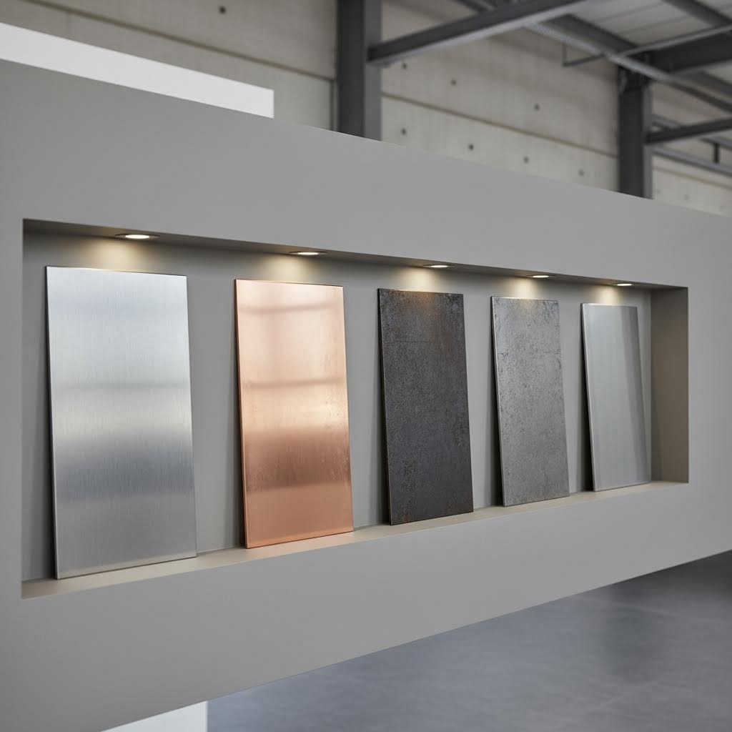
Specialty Metals and Their Applications
Beyond the steel and aluminum families, specialty metals serve niche but important roles in sheet fabrication. Bronze sheet metal finds use in decorative applications, marine hardware, and electrical components where its conductivity and corrosion resistance prove valuable. Copper sheets share similar properties with even better electrical and thermal conductivity, making them essential for heat exchangers, roofing, and electronics applications.
Brass offers excellent machinability alongside an attractive appearance, commonly appearing in decorative trim, musical instruments, and architectural features. Titanium, while expensive, provides an unmatched strength-to-weight ratio for aerospace and medical implant applications.
| Material Type | Common Gauges | Tensile Strength Range | Best Applications | Cost Tier |
|---|---|---|---|---|
| Carbon Steel | 16-24 gauge (1.5-0.6mm) | 400-550 MPa | Structural components, enclosures, automotive | $ |
| Stainless Steel 304 | 16-26 gauge (1.5-0.45mm) | 515-620 MPa | Food equipment, medical, architectural | $$$ |
| Stainless Steel 316 | 16-26 gauge (1.5-0.45mm) | 485-620 MPa | Marine, chemical processing, pharmaceutical | $$$$ |
| Aluminum 3003 | 14-24 gauge (1.8-0.5mm) | 110-150 MPa | HVAC, fuel tanks, general fabrication | $$ |
| Aluminum 5052 | 14-24 gauge (1.8-0.5mm) | 170-215 MPa | Marine, pressure vessels, automotive | $$ |
| Aluminum 6061-T6 | 14-20 gauge (1.8-0.8mm) | 270-310 MPa | Aerospace, structural, precision components | $$$ |
| Copper | 16-24 gauge (1.5-0.5mm) | 210-380 MPa | Electrical, heat exchangers, roofing | $$$$ |
| Bronze | 16-22 gauge (1.5-0.7mm) | 350-500 MPa | Marine hardware, decorative, bearings | $$$$ |
Your material choice cascades through every subsequent fabrication decision. Harder materials require more powerful cutting equipment and slower feed rates. Softer metals bend more easily but may spring back unexpectedly. Some materials weld beautifully while others demand specialized techniques or alternative joining methods entirely. Understanding these relationships upfront saves time, reduces scrap, and produces better finished parts.
With your material selected, the next step involves understanding exactly how that flat sheet transforms into your final component through a carefully orchestrated series of fabrication stages.
The Complete Sheet Metal Fabrication Process Explained
So how is sheet metal manufactured from a flat blank into the finished component sitting on your desk or installed in your vehicle? The sheet metal fabrication process follows a carefully orchestrated sequence where each stage builds upon the previous one. Miss a step or execute one poorly, and you'll face quality issues, cost overruns, or project delays downstream.
Understanding this sheet metal manufacturing process gives you leverage when communicating with fabricators, evaluating quotes, and troubleshooting problems. Let's walk through each stage in the order it typically occurs.
- Design and CAD Preparation - Creating detailed digital models with manufacturing specifications
- Material Selection and Procurement - Choosing appropriate metal type, grade, and thickness
- Cutting Operations - Separating material into blanks using laser, waterjet, or mechanical methods
- Forming and Bending - Transforming flat blanks into three-dimensional shapes
- Joining and Assembly - Connecting multiple components through welding, fastening, or riveting
- Surface Finishing - Applying protective or aesthetic treatments to completed parts
Design and Engineering Phase
Every successful sheet metal process starts long before any metal gets cut. During the design phase, engineers create detailed CAD models that define exact measurements, material specifications, and tolerance requirements. This isn't just about drawing pretty pictures - it's about ensuring your part can actually be manufactured.
Here's where Design for Manufacturing (DFM) principles become critical. According to Protolabs' DFM guidelines, common issues like improper bend reliefs, incorrect bend radii, and overlapping flanges can derail projects before they even reach the shop floor. A bend relief - essentially a small notch that prevents metal deformation at corners - should be no wider than 0.030 inches and no longer than the bend radius plus material thickness.
What about bend radius specifications? Standard tooling typically accommodates radii from 0.01 inches up to 1.0 inches. Designing outside these standards means custom tooling, longer lead times, and higher costs. The smarter approach? Work with your fabricator early to align your design with their capabilities.
Prototyping often bridges design and production. CNC machining remains the most common method for creating physical test models, offering precision and quick turnaround. For parts requiring extensive bending and forming, sheet metal prototyping using actual production methods provides more realistic validation of your design assumptions.
Cutting and Forming Operations
Once your design is finalized and material procured, sheet metal processing moves into physical transformation. Cutting operations create the initial blank - that flat shape containing all the material needed for your finished part.
The cutting method you choose affects everything downstream. Laser cutting delivers precision and speed for most materials. Waterjet cutting handles heat-sensitive materials without thermal distortion. Plasma cutting tackles thick steel economically. Shearing and sawing provide cost-effective options for simpler geometries. Your fabricator selects the optimal method based on material type, thickness, tolerance requirements, and edge quality specifications.
Punching operations create holes, slots, and other features using matched punch and die sets. The removed material - called a blank - can sometimes be repurposed for smaller parts, reducing waste and lowering costs. This sheet metal processing step requires careful planning to avoid weakening the surrounding material or creating distortion around the cut features.
Forming transforms your flat blank into a three-dimensional component. Press brakes create precise bends using V-shaped punch and die combinations. The material's properties determine how it behaves during bending - thinner sheets bend more easily, while thicker materials require greater force and larger bend radii. Springback compensation accounts for the metal's tendency to partially return toward its original flat state after bending.
Beyond simple bending, specialized forming techniques include rolling for curved surfaces, stamping for complex shapes, and spinning for cylindrical components. Each technique affects your part's dimensional accuracy, surface finish, and structural integrity differently.
Assembly and Finishing Steps
With individual components formed, the metal fabrication process moves into joining and assembly. This stage brings multiple pieces together into a unified structure using welding, mechanical fasteners, rivets, or adhesive bonding.
Welding fuses components by melting their edges together, creating permanent joints with strength often exceeding the base material. Different welding methods suit different materials and applications - MIG welding handles steel efficiently, while TIG welding provides the precision needed for aluminum and stainless steel. The heat generated during welding can cause distortion, so experienced fabricators plan weld sequences and use fixtures to maintain dimensional accuracy.
Mechanical fastening using screws, bolts, and nuts allows for disassembly and provides flexibility in assembly sequences. Riveting creates permanent connections without heat, preserving material properties in heat-sensitive applications. Adhesive bonding distributes loads across larger areas and joins dissimilar materials effectively.
Surface finishing represents the final transformation stage. Grinding removes weld marks and rough edges. Polishing creates smooth, reflective surfaces. Blasting prepares surfaces for subsequent coatings. Powder coating applies durable, attractive finishes that protect against corrosion and wear. The finishing method you choose affects both aesthetics and functional performance - a critical consideration for customer-facing components or parts exposed to harsh environments.
Quality inspection runs parallel to or follows each major stage. Visual inspections catch obvious defects, while dimensional verification ensures parts meet specified tolerances. Advanced non-destructive testing methods like ultrasonic or radiographic inspection validate weld integrity on critical components. According to KAL Manufacturing, experienced fabricators can achieve tolerances down to 0.003-0.005 inches on precision components.
Each stage in this sequence influences your project's quality, cost, and timeline. Rushing design creates manufacturing problems. Choosing inappropriate cutting methods affects edge quality and downstream forming. Poor weld preparation leads to weak joints or rework. Understanding these relationships helps you make informed decisions and communicate effectively with your fabrication partners.
Now that you understand the overall process flow, let's examine cutting methods in detail - the first physical transformation your material undergoes and a decision that ripples through every subsequent operation.
Cutting Methods Compared From Laser to Waterjet
Choosing the wrong cutting method can cost you thousands in wasted material and lost time. Each metal cutter technology excels in specific scenarios, and understanding these distinctions helps you match the right tool to your project requirements. Let's break down the four primary cutting approaches used in modern sheet fabrication.
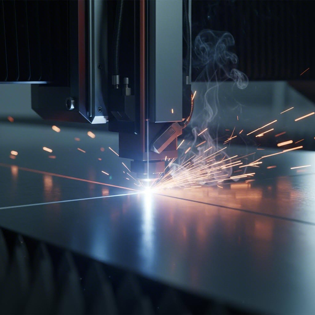
Laser Cutting Precision and Speed
When precision matters most, laser cutting delivers. A focused beam of intense light cuts through sheet metal with surgical accuracy, creating exceptionally clean edges that often require no secondary finishing. For thin materials and intricate designs, this technology outperforms nearly every alternative.
What makes a laser cutter stand out? According to Wurth Machinery's testing across multiple technologies, laser cutting excels specifically when working with:
- Thin sheets requiring fine details and precise holes
- Parts needing clean edges with minimal post-processing
- Complex designs with sharp corners and small radii
- High-volume production where speed matters
The kerf - that narrow channel of material removed during cutting - typically measures just 0.1mm to 0.3mm with laser technology. This minimal material removal means tighter nesting of parts on your sheet, reducing waste and lowering per-part costs. The narrow kerf also enables cutting fine details that wider-kerf methods simply cannot achieve.
However, lasers have limitations. Material thickness caps out around 25mm for steel, and thicker materials cut progressively slower. Heat generation can create a heat-affected zone along cut edges, potentially altering material properties in that narrow band. For heat-sensitive applications, you'll need an alternative approach.
Waterjet for Heat-Sensitive Materials
What happens when heat damage isn't acceptable? Waterjet cutting eliminates thermal concerns entirely. High-pressure water mixed with abrasive particles cuts through virtually any material - from titanium to stone - without generating significant heat. No warping. No hardening. No heat-affected zones altering your material's properties.
This cold-cutting capability makes waterjet indispensable for aerospace components, pre-hardened materials, and applications where maintaining original material characteristics is non-negotiable. The technology handles materials that lasers struggle with, including reflective metals, thick composites, and layered materials.
Wondering how to cut plexiglass or similar acrylics without cracking or melting? Waterjet handles these heat-sensitive plastics beautifully. The same applies when asking how do you cut perspex - the cold-cutting process preserves edge clarity and prevents the stress fractures that thermal methods often cause.
The tradeoffs? Waterjet cutting runs slower than laser or plasma for most metals, and operating costs typically run higher due to abrasive consumption. The kerf width ranges from 0.7mm to 1.5mm - significantly wider than laser - which affects nesting efficiency and limits minimum feature sizes. Still, the waterjet market is projected to exceed $2.39 billion by 2034, reflecting growing demand for its unique capabilities.
Plasma Cutting for Thick Metals
Need to cut 1-inch steel plate quickly and economically? Plasma cutting dominates this territory. An electrical arc combined with compressed gas creates superheated plasma that melts and blasts through conductive metals at impressive speeds.
For structural steel fabrication, heavy equipment manufacturing, and shipbuilding applications, plasma offers unmatched cost efficiency on thick materials. Testing data shows plasma cutting 1-inch steel runs approximately 3-4 times faster than waterjet, with operating costs roughly half as much per linear foot. A complete plasma system costs around $90,000 compared to approximately $195,000 for a similar-sized waterjet system.
Plasma cutting works exclusively with conductive metals - steel, aluminum, copper, and similar materials. Edge quality doesn't match laser precision, and the heat-affected zone is more pronounced. But when you're processing thick structural components where speed and cost matter more than fine detail, plasma delivers.
When CNC Routing Makes Sense
CNC routing carves out a niche in sheet fabrication, particularly for non-ferrous metals, plastics, and composite materials. The rotating cutting tool physically removes material rather than melting or eroding it, producing clean edges without thermal effects.
This mechanical approach works well for aluminum sheets, brass, and softer metals where tool wear remains manageable. For prototype runs and lower volumes, CNC routing often provides faster setup times than laser or waterjet systems. The technology also handles sheet thicknesses and material types that might challenge other methods.
Searching for metal cutting near me? Many local machine shops offer CNC routing services alongside more specialized cutting technologies, making it an accessible option for smaller projects and quick-turn prototypes.
| Method | Material Compatibility | Thickness Range | Precision Level | Edge Quality | Speed | Best Use Cases |
|---|---|---|---|---|---|---|
| Laser Cutting | Steel, stainless, aluminum, some plastics | 0.5mm - 25mm | ±0.1mm | Excellent - minimal burr | Very Fast | Precision parts, electronics, intricate designs |
| Waterjet | Any material including glass, stone, composites | 0.5mm - 200mm+ | ±0.1mm - 0.25mm | Excellent - no heat marks | Slow to Moderate | Heat-sensitive materials, aerospace, thick stock |
| Plasma | Conductive metals only | 3mm - 75mm+ | ±0.5mm - 1.5mm | Good - may need grinding | Fast | Structural steel, heavy plate, industrial fabrication |
| CNC Routing | Aluminum, brass, plastics, composites | 0.5mm - 50mm | ±0.05mm - 0.1mm | Very Good - clean mechanical cut | Moderate | Prototypes, non-ferrous metals, mixed materials |
How Cutting Method Affects Downstream Operations
Your cutting decision ripples through every subsequent fabrication stage. Edge quality from cutting directly impacts welding preparation - rough plasma-cut edges may need grinding before achieving proper weld penetration, while laser-cut edges often weld immediately. The heat-affected zone from thermal cutting can alter material hardness near edges, affecting how the metal behaves during bending operations.
Kerf width matters for dimensional accuracy. When your design includes features that must align precisely after bending, accounting for the specific kerf of your chosen cutting method during CAD preparation prevents assembly problems later. Wider kerfs also limit minimum web widths between adjacent cuts and affect material utilization rates.
For parts requiring subsequent forming, the absence of thermal effects makes waterjet and CNC routing attractive despite slower speeds. Springback during bending becomes more predictable when edge properties remain uniform. Similarly, parts destined for powder coating or other surface treatments benefit from laser cutting's clean edges that require minimal preparation.
The practical decision framework comes down to matching method capabilities to your specific requirements: material type, thickness, precision needs, edge quality standards, volume, and budget constraints. Many fabrication shops maintain multiple cutting technologies precisely because no single method handles every scenario optimally.
With your blanks cut to specification, the next transformation stage awaits - bending and forming operations that convert those flat pieces into three-dimensional components with precise geometry and structural integrity.
Bending and Forming Techniques That Shape Your Parts
You've got your flat blanks cut precisely to shape. Now comes the transformation that gives sheet fabrication its real magic - converting those two-dimensional pieces into functional three-dimensional components. Bending and forming operations reshape metal without adding or removing material, relying instead on the metal's inherent plasticity to create angles, curves, and complex geometries.
What separates a successful forming operation from one that cracks, wrinkles, or springs back out of tolerance? Understanding the specific tools, techniques, and calculations involved. Let's break down the primary forming methods and the critical parameters that determine your results.
- Press brake bending - Creates precise angular bends using punch and die tooling; ideal for brackets, enclosures, and structural components
- Roll forming - Produces continuous profiles through progressive roller stations; best for high-volume production of uniform cross-sections
- Stamping - Forms complex shapes in single press operations; suited for mass production of identical parts
- Deep drawing - Stretches sheet metal into cup-shaped components; used for cookware, automotive panels, and containers
- Hydroforming - Uses pressurized fluid to shape metal over dies; excellent for complex curves with uniform thickness
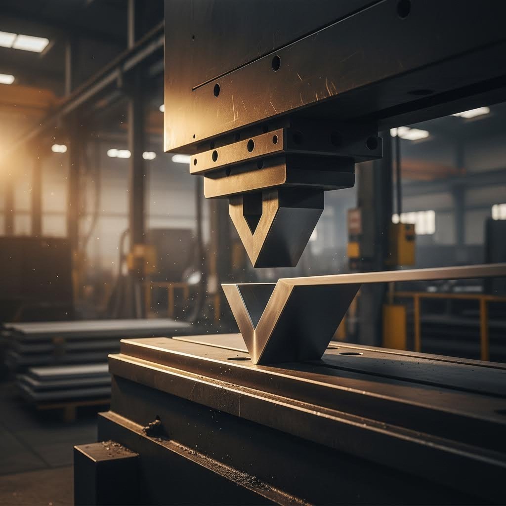
Press Brake Bending Fundamentals
The press brake remains the workhorse of steel sheet bending operations. This machine combines an upper tool called a punch with a lower tool called a die, pressing the sheet metal between them to create angular bends. Sounds simple, right? The execution requires careful attention to multiple interdependent variables.
First, consider your bend radius - the inside curvature where the metal transitions from flat to angled. According to PEKO Precision's guidelines based on Machinery's Handbook, minimum bend radius depends directly on material type and thickness. Mild steel typically requires a bend radius of 1.5 times material thickness, while aluminum needs about 2.0 times thickness. Attempt a tighter radius than your material allows, and you'll see cracking on the outer surface where tensile stress exceeds the metal's limits.
The minimum flange length represents another critical constraint. This is the shortest distance from your bend line to the edge of the sheet. Press brake specialists at Moore Machine Tools explain that attempting to bend a flange shorter than this limit causes the material to twist, deform, or tear because it cannot seat correctly on the die.
What about bend allowance? When metal bends, the outer surface stretches while the inner surface compresses. The neutral axis - that imaginary line where neither stretching nor compression occurs - shifts during bending. Bend allowance calculations account for this material displacement, ensuring your flat pattern dimensions produce the correct final geometry. The K-factor, typically ranging from 0.3 to 0.5 depending on material and process, quantifies where the neutral axis falls within the material thickness.
Perhaps the most frustrating challenge in bending operations is springback compensation. After you release the bending force, the metal partially returns toward its original flat state due to elastic recovery. Harder materials spring back more than softer ones. Tighter bend radii produce more springback than gradual curves. Experienced operators use overbend compensation - intentionally bending beyond the target angle knowing the material will relax back to specification.
Flange angle tolerance in demanding industries like automotive and aerospace often requires ±0.5 degrees or tighter. Achieving this precision demands regular monitoring for tool wear and consistent machine calibration. A worn punch or die subtly shifts bending angles over time, causing parts to drift out of specification.
Stamping for High-Volume Production
When your production volumes climb into thousands or millions of identical parts, custom metal stampings become the economically superior choice. Stamping presses with capacities reaching 400 tons or more can form components as thin as 0.005 inches while maintaining tight tolerances - all at production speeds measured in strokes per minute rather than parts per hour.
The stamping process feeds sheet metal blanks into a press where hardened tool steel dies shape the material in single or progressive operations. Progressive die stamping advances the strip through multiple stations, each performing a specific forming or cutting operation, until a completed part exits the final station. This efficiency makes stamping unmatched for producing door handles, automotive brackets, appliance components, and countless other high-volume parts.
If you're preparing for a role in this field, researching a metal stamping interview questions pdf can help you understand the technical knowledge employers expect - from die clearance calculations to tonnage requirements and material flow considerations.
Finding metal stamping near me involves evaluating shops based on their press capacities, die-making capabilities, and experience with your specific materials and part geometries. Larger stamping operations often specialize in particular industries, developing expertise in the tolerances and certifications those markets demand.
Specialized Forming Techniques
Beyond standard bending and stamping, specialized forming techniques address geometries that conventional methods cannot achieve efficiently.
Roll forming passes sheet metal through a series of paired roller stations, each progressively shaping the material into the desired profile. This continuous process excels at producing long components with consistent cross-sections - think roofing panels, structural channels, and storage shelving. The gradual deformation minimizes stress on the material while maintaining tight dimensional control across production runs measured in linear feet.
Deep drawing stretches sheet metal into cup-shaped components with depth exceeding half their diameter. The process uses a blank holder to control material flow as a punch forces the sheet into a die cavity. According to Geomiq's technical analysis, both the die and punch experience significant wear due to forming pressures, which is why they're constructed from durable tool steel or carbon steel. Applications range from kitchen sinks and automotive fuel tanks to beverage cans and ammunition casings.
Hydroforming employs pressurized fluid - typically water-based - to push sheet metal against a die surface, creating complex curved shapes with uniform wall thickness. The process produces parts with excellent surface finish and structural integrity, making it popular for aerospace structural components and automotive body panels. Initial equipment costs run higher than conventional stamping, but hydroforming often reduces the number of forming operations needed for complex geometries.
When selecting iron fabrication tools and forming methods, consider these tolerance expectations as baseline specifications:
- Press brake bending - Angular tolerance ±0.5° to ±1°; dimensional tolerance ±0.25mm to ±0.5mm
- Stamping operations - Dimensional tolerance ±0.05mm to ±0.15mm for precision work
- Roll forming - Profile tolerance ±0.25mm; length tolerance ±1.5mm per meter
- Deep drawing - Wall thickness variation ±10% of nominal; diameter tolerance ±0.1mm to ±0.25mm
Die clearance - the gap between punch and die - requires careful calibration based on material thickness and type. Insufficient clearance creates excessive stress and potential tool damage, while excessive clearance produces poor edge quality and dimensional inconsistency. Standard recommendations call for 5-7% of material thickness for softer metals like aluminum and 7-10% for steel and stainless steel.
Each forming method imparts specific characteristics to your finished parts - from surface finish and residual stress patterns to achievable tolerances and minimum feature sizes. Matching the right technique to your geometry, volume, and quality requirements prevents costly rework and ensures your components perform as designed.
With your parts now bent and formed into three-dimensional shapes, the next challenge involves joining multiple components into unified assemblies - a stage where welding, fastening, and adhesive methods each offer distinct advantages.
Joining Methods From Welding to Mechanical Fastening
Your formed components now need to become unified assemblies. How you connect those pieces determines joint strength, production speed, cost efficiency, and whether your finished product can be serviced or disassembled later. Joining sheet metal involves choosing between permanent fusion methods like welding and brazing sheet metal, mechanical connections using fasteners and rivets, or adhesive bonding - each with distinct advantages for specific applications.
The right joining method depends on your material type, required joint strength, production volume, and end-use environment. Let's examine each approach so you can match the technique to your project requirements.
MIG vs TIG Welding Selection
When comparing tig vs mig welding, both create durable, permanent joints - but they excel in different scenarios. Understanding these differences helps you specify the right process for your application.
MIG (Metal Inert Gas) welding, also called GMAW, strikes an arc between a continuously fed wire electrode and your workpiece. The process runs faster because the machine feeds filler material automatically, freeing the welder to focus on travel speed and positioning. This efficiency makes MIG the preferred choice for large-scale projects requiring sturdy welds - structural steel fabrication, automotive frames, heavy equipment, and general sheet metal assembly.
TIG (Tungsten Inert Gas) welding uses a non-consumable tungsten electrode with separately added filler rod. The welder controls heat input via a foot pedal while manually feeding filler material - demanding coordination between both hands and one foot simultaneously. This complexity translates to slower production speeds but exceptional precision and control.
When does TIG make sense? According to welding experts at ETI Campus, TIG produces stronger, more precise welds and works better for thinner materials like aluminum, copper, and low-alloy steels. The aerospace, motorsport, and precision equipment industries rely on TIG for critical joints where appearance and strength both matter.
Aluminum welding presents unique challenges regardless of method. Midwest Metal Products emphasizes that aluminum's sensitivity to oxide and hydrocarbon contamination demands thorough cleaning of both base metal and filler rod. The workspace must remain pristinely clean to prevent contamination that weakens joints. Both MIG and TIG work for aluminum, but TIG's precision control often produces superior results on thinner gauges.
Stainless steel fabrication through welding introduces different concerns. The heat required can cause warping, discoloration, and loss of corrosion resistance in the heat-affected zone. Secure fixtures prevent warping during welding, while inert gas purging techniques protect the back side of welds from atmospheric contamination that causes discoloration.
Mechanical Fastening Options
Not every joint needs permanent fusion. Mechanical fasteners - screws, bolts, and nuts - provide removable connections that allow disassembly for service, repair, or component replacement. This flexibility makes fastening essential for enclosures, access panels, and assemblies requiring periodic maintenance.
Mechanical fastening requires precise hole alignment between mating parts, adding a step to your fabrication process. The overlapping joint geometry or use of connecting plates adds weight to finished assemblies. Holes also create potential stress concentration points and corrosion initiation sites if not properly protected.
Despite these considerations, fasteners offer unmatched convenience for assembly and field serviceability. Different fastener types serve different needs - square nuts provide greater contact on large surfaces, while knurled nuts enable hand installation without tools. Thread-locking compounds prevent loosening under vibration, and captive fasteners stay attached to one component for easier assembly.
When to Use Rivets or Adhesives
Rivets create robust permanent joints without heat input, making them ideal for heat-sensitive materials and applications experiencing temperature or pressure fluctuations. According to TWI Global, rivets have proven themselves across diverse applications from vehicles to buildings and tools.
Various rivet types serve specific purposes: pop rivets for blind-side installation, solid rivets for maximum strength, threaded rivets for removable connections. The downsides? Riveting generates noise, requires special equipment, adds weight, and proves difficult to correct when mistakes occur. Drilling out incorrectly placed rivets damages surrounding material.
Adhesive bonding offers advantages that surprise many engineers. Industrial adhesives cost less than mechanical fasteners while providing corrosion resistance and vibration dampening. They distribute loads across entire bond areas rather than concentrating stress at fastener holes. When appearance matters, adhesives create invisible joints unmarred by visible fasteners.
Successful adhesive bonding demands proper surface preparation - solvents remove oils, oxides, and contaminants that prevent adhesion. Thin adhesive layers perform better than thick ones, which can develop cracks. Joint design should emphasize shear, tension, and compression loading while avoiding cleavage or peel forces that adhesives resist poorly.
| Method | Joint Strength | Speed | Cost | Skill Required | Best Applications |
|---|---|---|---|---|---|
| MIG Welding | Excellent - often exceeds base metal | Fast | Moderate | Moderate | Structural steel, automotive, high-volume production |
| TIG Welding | Excellent - superior precision | Slow | Higher | High | Aerospace, thin materials, aluminum, stainless steel |
| Mechanical Fasteners | Good - depends on fastener grade | Fast | Low to Moderate | Low | Serviceable assemblies, enclosures, access panels |
| Rivets | Very Good - permanent | Moderate | Moderate | Moderate | Aerospace, heat-sensitive materials, structural joints |
| Adhesive Bonding | Good - shear loads | Slow (cure time) | Low | Low to Moderate | Appearance-critical, vibration damping, dissimilar materials |
| Brazing | Good - filler metal dependent | Moderate | Moderate | Moderate to High | Electronic components, small joints, copper and brass |
Quality inspection for welded joints includes visual examination for porosity, undercut, and incomplete fusion, plus destructive or non-destructive testing on critical components. Fastened joints require torque verification and periodic inspection for loosening. Adhesive bonds benefit from peel or lap-shear testing on sample coupons to verify proper cure and adhesion strength.
Surface preparation before any joining method proves critical. Welding requires clean, oxide-free surfaces for proper fusion. Fasteners need properly sized, deburred holes. Adhesives demand contamination-free surfaces with appropriate roughness for mechanical bonding. Skipping preparation steps leads to joint failures that compromise your entire assembly.
With your components now joined into complete assemblies, understanding how different industries apply these fabrication techniques - and the certifications they require - becomes essential for targeting the right markets with your manufactured parts.
Industry Applications and Certification Requirements
Every industry that uses metal fabrication brings its own rulebook to the table. What passes inspection in construction might fail catastrophically in aerospace. The tolerances acceptable for HVAC ductwork would never satisfy automotive chassis requirements. Understanding these industry-specific demands helps you specify the right materials, processes, and quality standards for your application.
Metal fabrication companies serving multiple industries must maintain different certification levels and quality systems simultaneously. Let's examine what each major sector requires from their fabricated components - and why those requirements exist.
Automotive Chassis and Structural Components
The automotive industry runs on precision sheet metal fabrication at massive scale. From chassis rails and suspension brackets to body panels and structural reinforcements, vehicles depend on fabricated components that meet exacting specifications while keeping costs competitive.
What separates automotive-grade fabrication from general industrial work? Certification requirements - specifically IATF 16949, the quality management system developed by the International Automotive Task Force. This framework builds on ISO 9001 but adds automotive-specific requirements focused on defect prevention, consistency, and continuous improvement across the supply chain.
- Tolerances - Typically ±0.1mm to ±0.25mm for structural components; tighter for precision assemblies
- Required certifications - IATF 16949 for Tier 1 and Tier 2 suppliers; ISO 9001 minimum
- Material preferences - High-strength low-alloy steels, advanced high-strength steels, aluminum 5052 and 6061
- Critical factors - Repeatability across high volumes, dimensional consistency, weld integrity, corrosion resistance
IATF 16949 certification represents a binary qualification - you either meet the standard or you don't. According to Xometry's certification guide, the standard spans seven major sections covering everything from organizational context to performance evaluation. Suppliers without this certification often find themselves locked out of automotive supply chains entirely, as OEMs and Tier 1 suppliers won't risk working with non-certified partners.
For manufacturers seeking IATF 16949-certified precision sheet metal fabrication, Shaoyi (Ningbo) Metal Technology exemplifies the capabilities automotive programs demand - offering 5-day rapid prototyping alongside automated mass production for chassis, suspension, and structural components. Their comprehensive DFM support and 12-hour quote turnaround demonstrate the responsiveness modern automotive supply chains require.
Aerospace Precision Requirements
If automotive demands seem strict, aerospace takes precision to another level entirely. Components flying at 30,000 feet face fatigue cycles, temperature extremes, and safety requirements where failure simply isn't an option.
Aerospace sheet metal fabrication requires ITAR registration and ISO 9001:2015 certification at minimum, with many programs requiring AS9100 certification specifically designed for aviation, space, and defense. NADCAP accreditation covers special processes like welding, heat treating, and finishing that affect structural integrity.
- Tolerances - Often ±0.05mm or tighter for critical dimensions; specialized inspection equipment required
- Required certifications - ITAR registration, ISO 9001:2015, AS9100, NADCAP for special processes
- Material preferences - 5052-H32 aluminum (preferred for formability), 6061-T6 for high strength, titanium, Inconel
- Critical factors - Full material traceability, AS9102 first article inspection, process documentation, heat treatment records
Material selection in aerospace involves tradeoffs that don't exist in other industries. While 6061-T6 aluminum offers superior strength, Approved Sheet Metal notes this heat-treated alloy is extremely hard and prone to cracking during forming - especially at 90-degree bends. Their fabrication specialists recommend 5052-H32 aluminum for most applications, reserving harder alloys for situations where their strength truly justifies the additional handling challenges.
Industrial fabrication services targeting aerospace must also navigate supply chain complexities. Certain stainless steel grades face extended lead times and minimum purchase requirements that can derail project timelines. Experienced precision sheet metal fabrication companies communicate material availability concerns early, offering alternative specifications when original callouts prove impractical.
Electronics Enclosures and Housings
Electronics fabrication prioritizes different characteristics than structural applications. While strength matters, electromagnetic compatibility (EMI) shielding, thermal management, and cosmetic appearance often drive material and process decisions.
According to EE World's design guide, sheet metal enclosures offer electrical conductivity essential for EMI applications - reducing emissions while protecting sensitive electronics from external noise. The material's lightweight, non-corrosive properties make it particularly popular across electronics applications from server chassis to NEMA-rated electrical boxes.
- Tolerances - ±0.25mm typical for enclosures; tighter for PCB mounting features and mating surfaces
- Required certifications - ISO 9001; UL certification for safety-critical enclosures; IP ratings for environmental protection
- Material preferences - Aluminum (lightweight, good shielding), cold-rolled steel with conductive coatings, stainless for harsh environments
- Critical factors - EMI/RFI shielding effectiveness, thermal dissipation, cosmetic finish quality, hardware insertion precision
Design for manufacturing becomes critical in electronics enclosures. Rapid's applications engineers emphasize maintaining uniform wall thickness throughout - you cannot combine 14-gauge bases with 16-gauge flanges without welding separate components. The 4x rule applies throughout: flange lengths must equal at least 4x material thickness, and holes or slots must sit at least 4x material thickness away from bend lines to prevent distortion.
Construction and Industrial Equipment
Construction and heavy equipment applications favor durability and cost-effectiveness over extreme precision. Structural brackets, equipment housings, ductwork, and architectural panels tolerate wider tolerances while demanding reliable performance under harsh conditions.
- Tolerances - ±0.5mm to ±1.0mm acceptable for most structural applications
- Required certifications - AWS welding certifications; structural steel fabrication credentials; building code compliance
- Material preferences - Carbon steel (cost-effective, strong), galvanized steel for corrosion resistance, aluminum for weight-sensitive applications
- Critical factors - Weld quality and consistency, protective coatings, load-bearing capacity, weather resistance
Industrial fabrication in these sectors often emphasizes volume and speed over precision. Plasma cutting handles thick structural plates economically. MIG welding joins components rapidly with acceptable quality for non-critical joints. Powder coating provides durable, cost-effective protection against corrosion and wear.
However, specialized industrial equipment may require tighter controls. Medical equipment enclosures demand stainless steel fabrication with sanitary finishes. Food processing equipment requires FDA-compliant materials and seamless welds that prevent bacterial growth. These applications bridge the gap between general industrial work and precision manufacturing.
Matching Capabilities to Requirements
When evaluating metal fabrication companies for your project, certification alignment matters enormously. A shop producing excellent automotive components may lack the certifications, inspection equipment, or process controls aerospace programs demand. Conversely, aerospace-certified precision sheet metal fabrication companies may price themselves out of cost-sensitive construction applications.
Key questions to ask potential fabrication partners:
- What industry certifications do you currently maintain?
- Can you provide material certifications and full traceability?
- What inspection equipment and quality procedures do you employ?
- Do you have experience with my specific material and tolerance requirements?
- What is your capacity for my expected production volumes?
Rapid prototyping capabilities also matter for development programs. Fabricators offering quick-turn prototypes using production-representative processes help you validate designs before committing to full production tooling. This approach reduces risk and accelerates time-to-market across all industry applications.
Understanding industry requirements upfront prevents costly mismatches between your specifications and your fabricator's capabilities. But even with the right partner and proper certifications, defects can occur - making quality control and troubleshooting essential skills for anyone managing fabrication projects.
Troubleshooting Common Defects and Quality Control
Even the best sheet metal fabrication processes occasionally produce parts that don't meet specifications. When defects appear, understanding their root causes helps you work effectively with your fabricator to prevent recurrence. Whether you're seeing warped panels, cracked bends, or dimensions that drift outside tolerance, systematic troubleshooting transforms frustrating quality issues into solvable problems.
Quality control in sheet metal fabricating isn't just about catching defects - it's about preventing them before they occur. According to New Mexico Metals' quality control guidelines, the process starts before any metal enters the bending machine. Design reviews, material verification, and process monitoring all contribute to accurate metal fabricating outcomes that meet your specifications consistently.
Preventing Warping and Distortion
Warping frustrates engineers and fabricators alike. Your flat panel comes out curved, or your welded assembly twists out of alignment. What's happening, and how do you fix it?
- Thermal distortion from welding - Heat input causes localized expansion, then contraction during cooling pulls the material out of shape. Prevention strategies include proper weld sequencing, intermittent welding patterns, and using fixtures to constrain parts during cooling.
- Residual stress release during cutting - Laser or plasma cutting introduces heat that can release internal stresses in the sheet, causing unexpected movement. Allow stress-relieved material for critical flat parts, or plan for secondary flattening operations.
- Uneven forming forces - Improper die alignment or inconsistent blank holder pressure during stamping creates uneven deformation. Regular machine calibration and die maintenance prevent this drift.
- Springback overcorrection - Compensating too aggressively for springback can push parts past their target geometry. Develop material-specific springback factors through testing rather than relying solely on theoretical calculations.
For critical flatness requirements, specify your tolerance explicitly. General sheet metal fabrication processes typically hold flatness within 0.5mm per 300mm of length. Tighter requirements - say 0.25mm per 300mm - may require stress relieving, precision leveling, or selecting pre-flattened material grades.
Addressing Edge Quality Issues
Burrs, rough edges, and edge cracking create both functional and safety problems. Sharp burrs can injure assembly workers, interfere with mating parts, or compromise coating adhesion. Understanding why these defects occur points toward effective solutions.
- Burrs from punching and shearing - Worn tooling, excessive clearance between punch and die, or improper cutting speed create raised material on cut edges. According to industry research, maintaining cutting tool quality and adjusting clearance based on material thickness prevents most burr formation.
- Rough laser-cut edges - Incompatible power settings for material thickness, dirty optics, or incorrect focus distance produce poor edge quality. Proper machine setup and regular maintenance restore clean cutting performance.
- Edge cracking during bending - Attempting bend radii tighter than the material allows causes the outer surface to fracture. Respect minimum bend radius guidelines - typically 1.5x material thickness for mild steel, 2.0x for aluminum.
- Microfractures from excessive hardness - Work-hardened material or inappropriate alloy selection for forming operations leads to cracking. Material testing before fabrication identifies problematic stock.
Secondary deburring operations - tumbling, vibratory finishing, or manual grinding - remove burrs when prevention isn't practical. Specify your edge condition requirements clearly: "burr-free" means different things to different fabricators without quantifiable acceptance criteria.
Dimensional Accuracy Troubleshooting
When parts don't fit together or fail functional checks, dimensional inaccuracies typically trace back to specific process stages. According to Protocase's tolerance guidelines, a certain amount of dimensional variance is inherent in fabrication processes - the key is understanding expected limits and designing accordingly.
Standard fabrication techniques achieve these typical tolerances:
- Laser cutting - ±0.1mm on cut features for most materials and thicknesses
- Press brake bending - ±0.25mm to ±0.5mm on bent dimensions; ±0.5° to ±1° on bend angles
- Hole positions - ±0.1mm to ±0.25mm depending on cutting method
- Overall part dimensions - ±0.25mm to ±0.5mm for most sheet metal production work
- Hardware insertion - ±0.1mm positional accuracy typical for CNC-inserted fasteners
When dimensions drift outside these ranges, investigate systematically:
- Cutting stage errors - Check CAD file accuracy, material thickness verification, and cutting machine calibration. Wrong material thickness throws off all subsequent bend calculations.
- Bending calculation mistakes - Incorrect K-factor or bend allowance assumptions produce parts that unfold to wrong flat pattern dimensions. Request bend samples to verify actual material behavior.
- Fixture and setup problems - Parts positioned incorrectly during forming or welding accumulate errors at each operation. Proper fixturing and work-holding ensure repeatability.
- Tool wear - Gradual die and punch wear causes dimensional drift that may go unnoticed until parts fail inspection. Implement statistical process control to catch drift early.
When working with fabricators to resolve quality issues, documentation accelerates problem-solving. Provide specific measurements showing how received parts deviate from specifications. Identify which features are critical versus those with flexibility. Share your end-use application context so fabricators understand why certain tolerances matter.
Visual inspection catches obvious defects, but dimensional verification requires appropriate measurement tools - calipers, micrometers, CMM equipment for complex geometries. Random sampling and detailed documentation of inspection results help identify patterns and enable root cause analysis when problems recur.
Effective quality control creates a feedback loop: defects trigger investigation, investigation identifies causes, corrective actions prevent recurrence. This continuous improvement approach - embedded in certification standards like IATF 16949 - transforms sheet metal production from reactive firefighting into proactive quality management.
With quality control systems in place to catch and prevent defects, the final piece of your fabrication knowledge involves understanding what drives costs - and how to get accurate quotes that reflect your project's true requirements.
Cost Factors and Getting Accurate Fabrication Quotes
Why do two seemingly identical sheet metal quotes differ by 40%? Understanding what drives fabrication costs helps you compare proposals accurately, optimize your designs for cost efficiency, and avoid unpleasant surprises when invoices arrive. Whether you're searching for sheet metal fabrication near me or evaluating overseas suppliers, the same fundamental cost drivers apply.
According to E-Abel's cost estimation guide, sheet metal fabrication cost is not just about raw material - it's a combined result of materials, processes, labor, tooling, and overhead. Let's break down each factor so you can make informed decisions and communicate effectively with potential fabricators.
Material and Thickness Cost Factors
Material typically represents 30-50% of your total part cost, making it the largest single line item on most quotes. Several variables determine what you'll pay:
- Material type and grade - Stainless steel costs significantly more than mild steel, while specialty alloys like titanium or Inconel multiply costs further. According to Komacut's pricing analysis, aluminum offers a middle ground - more expensive than mild steel but considerably less than stainless.
- Sheet thickness - Thicker materials cost more per square foot and require longer processing times. A 3mm steel sheet doesn't just use more material than a 1.5mm sheet - it cuts slower, bends harder, and may require different tooling.
- Nesting efficiency - How many parts fit on a standard sheet determines your actual material cost per part. Poor nesting increases scrap percentage, raising per-part costs even when raw material prices stay constant.
- Material availability - Common grades ship quickly from stock. Specialty alloys may require minimum order quantities and extended lead times that affect both cost and schedule.
Smart tip: When prototyping, consider using less expensive materials that share similar fabrication characteristics with your production material. Validating a design in mild steel before committing to stainless can save significant development costs.
How Complexity Affects Pricing
Part complexity drives processing time - and processing time drives cost. Every additional feature, tighter tolerance, or specialized operation adds to your quote.
- Cut complexity - More holes, slots, and intricate contours increase laser cutting time. A simple rectangular blank costs far less than an intricately patterned part of the same size.
- Number of bends - Each bend requires machine setup, positioning, and forming time. CNC bending is typically calculated per bend or by machine time, with complex bends, tight angles, and frequent tool changes adding to processing cost.
- Tolerance requirements - Standard tolerances (±0.25mm to ±0.5mm) come at base pricing. Tighter tolerances require slower processing, additional inspection, and often higher rejection rates - all reflected in higher per-part costs.
- Secondary operations - Hardware insertion, deburring, welding, and assembly add labor and machine time. Each additional operation also introduces potential for rework.
- Surface finishing - Powder coating, plating, anodizing, or specialized finishes add measurable cost per part or batch. Many finishing processes are priced per batch, not per part - smaller batches increase per-part cost while larger volumes help spread the expense.
Design for Manufacturing (DFM) optimization directly reduces complexity-related costs. Fabricators offering comprehensive DFM support - like Shaoyi Metal Technology with their 12-hour quote turnaround - can identify cost-saving design modifications before you commit to production. Simple changes like adjusting bend radii to match standard tooling or repositioning holes to improve nesting can reduce costs 15-25% without affecting functionality.
Volume Discounts and Prototyping Costs
Production quantity dramatically affects per-part pricing through several mechanisms:
- Setup cost amortization - Machine setup time gets divided across all parts in a run. A 30-minute setup adds $50 per part on a 10-piece order but only $0.50 per part on a 1,000-piece run.
- Tooling amortization - Custom dies, fixtures, and jigs should be amortized over production quantity. Tooling costs are often underestimated or ignored during early quoting, leading to unexpected losses when they're charged separately for low volumes or prototypes.
- Material purchasing efficiency - Larger orders enable better material pricing and improved nesting across multiple sheets.
- Labor efficiency - Operators become faster as they repeat the same operations. Lower production volumes reduce labor efficiency, increasing per-part cost compared to high-volume runs.
When you need a sheet metal prototype for design validation, expect to pay a premium per part. Rapid sheet metal prototyping services optimize for speed rather than cost efficiency. However, this investment often saves money overall by catching design problems before you've committed to production tooling.
Looking for metal fabrication near me or fabrication shops near me? Proximity affects shipping costs and enables easier collaboration during development. However, don't limit your search based solely on location - the right fabricator with appropriate capabilities may offer better value even with higher shipping costs.
Getting Accurate Quotes
The quality of your quote request directly affects the accuracy of responses you receive. Provide fabricators with:
- Complete CAD files - 3D models in native or universal formats (STEP, IGES) with flat pattern drawings
- Material specifications - Alloy, temper, thickness, and any special requirements
- Tolerance callouts - Identify critical dimensions versus general tolerances
- Quantity requirements - Include prototype quantities, initial production volumes, and annual estimated usage
- Finishing specifications - Surface treatment, coating, hardware, and assembly requirements
- Lead time expectations - Standard versus expedited delivery needs
When comparing quotes from sheet metal fabrication shops near me or remote suppliers, ensure you're evaluating equivalent scopes. According to Hubs' cost reduction guide, fabrication can have relatively high labor costs - so quotes that seem low may exclude operations you assumed were included.
Watch for these common quote comparison pitfalls:
- Tooling charged separately versus amortized into part price
- Finishing and secondary operations included versus excluded
- Inspection and certification documentation costs
- Packaging and shipping terms
- Quote validity period and material price escalation clauses
Metal prices change frequently due to market conditions. Using outdated prices leads to underquoting or overpricing. Many fabricators apply material surcharges and limit quote validity to manage this risk - understand these terms before comparing bottom-line numbers.
When evaluating potential partners for custom sheet metal fabrication near me or globally, rapid quote turnaround indicates responsiveness and process maturity. Fabricators who can deliver detailed quotes quickly typically have well-organized operations and clear costing methodologies - both indicators of reliable production performance. The combination of fast quoting, comprehensive DFM feedback, and transparent pricing creates partnerships that optimize both cost and quality across your fabrication projects.
Frequently Asked Questions About Sheet Fabrication
1. What is sheet fabrication?
Sheet fabrication is the manufacturing process of transforming flat metal sheets into functional three-dimensional components through cutting, bending, punching, and assembly operations. This process works with materials like steel, aluminum, stainless steel, and specialty metals ranging from 0.5mm to 6mm thick. The workflow typically includes CAD design, material selection, precision cutting (laser, waterjet, or plasma), forming with press brakes, joining through welding or fasteners, and surface finishing. Industries from automotive to aerospace rely on sheet fabrication for everything from chassis components to electronics enclosures.
2. How much does it cost to fabricate sheet metal?
Sheet metal fabrication costs depend on multiple factors including material type (stainless steel costs more than mild steel), sheet thickness, part complexity, tolerance requirements, quantity, and finishing specifications. Material typically represents 30-50% of total part cost. Setup costs get amortized across production runs, making larger quantities more cost-effective per part. Complexity adds cost through increased cutting time, number of bends, and secondary operations like hardware insertion or powder coating. For accurate quotes, provide fabricators with complete CAD files, material specifications, tolerance callouts, and quantity requirements.
3. Is sheet metal fabrication a good trade?
Sheet metal fabrication offers a technical and satisfying career path with diverse opportunities. The trade encompasses various specializations from press brake operation and welding to CNC programming and quality inspection. As you gain experience, options expand into supervisory roles, engineering positions, or specialized work in demanding industries like aerospace and automotive. The skills are transferable across multiple sectors including construction, HVAC, electronics manufacturing, and precision equipment. With IATF 16949 and AS9100 certifications becoming increasingly important, qualified fabricators with quality management expertise are particularly valued.
4. What materials can be used in sheet metal fabrication?
Common sheet fabrication materials include carbon steel (cost-effective for structural components), stainless steel 304 and 316 (corrosion-resistant for food, medical, and marine applications), and aluminum grades 3003, 5052, and 6061 (lightweight for aerospace and automotive). Specialty metals like copper provide excellent electrical conductivity for heat exchangers, while bronze offers corrosion resistance for marine hardware. Material selection impacts fabrication method choices - harder materials require slower cutting speeds, softer metals may spring back unexpectedly during bending, and some materials need specialized welding techniques.
5. What certifications matter for sheet metal fabrication suppliers?
Certification requirements vary by industry. Automotive applications typically require IATF 16949 certification, which focuses on defect prevention and supply chain consistency. Aerospace demands ITAR registration, ISO 9001:2015, AS9100 certification, and NADCAP accreditation for special processes like welding. Electronics fabrication often requires UL certification for safety-critical enclosures and IP ratings for environmental protection. General industrial work typically needs ISO 9001 and AWS welding certifications. When evaluating suppliers, verify their certifications match your industry requirements and confirm they can provide material traceability and inspection documentation.