 Small batches, high standards. Our rapid prototyping service makes validation faster and easier —

Selecting Forged Rods For High RPM: Stop Guessing, Start Engineering
Understanding High RPM Demands on Connecting Rods
Imagine a component in your engine experiencing 16,000 pounds of tension—then reversing to compression—thousands of times per minute. That's exactly what connecting rods endure at high RPM. According to Chrysler engineering data from a 426 Hemi running at 7,200 RPM, the reciprocating assembly experiences acceleration forces exceeding 4,600 Gs. At these speeds, connecting rods in an engine aren't just transferring power—they're fighting physics itself.
Why RPM Changes Everything for Rod Selection
What is a connecting rod's primary job? It converts the piston's up-and-down motion into rotary motion at the crankshaft. Sounds simple enough. But here's what most builders underestimate: the forces acting on connecting rods multiply exponentially as engine speed climbs.
At high RPM—typically 7,000 RPM and above—inertia forces completely overshadow combustion loads. When your piston reaches top dead center and suddenly reverses direction, the connecting rod experiences maximum tension. This occurs not during the power stroke, but during the overlap stroke when there's no combustion pressure to counteract that violent direction change.
The highest load on a connecting rod occurs at overlap TDC—not during combustion—and is caused entirely by the inertia of the reciprocating assembly accelerating at thousands of Gs.
The Breaking Point: When Stock Rods Fail
Stock connecting rods are engineered for reliability at factory RPM limits—typically around 3,600 to 6,500 RPM depending on the application. Push beyond these limits, and you're gambling with components never designed for such abuse. The failure modes are predictable yet devastating:
- Big-end distortion: Tension loads stretch the rod, causing the large end to become egg-shaped and squeeze out the oil film
- Lubrication starvation: At sustained high RPM, oil bleeds from critical bearing surfaces faster than it can be replenished
- Fatigue cracking: Cyclic stress loading causes microscopic cracks to propagate until catastrophic failure occurs
This article provides a structured decision framework for selecting forged rods based on your specific RPM targets and application requirements. Whether you're building a naturally aspirated screamer or a boosted street/strip combination, understanding these forces is the first step toward making informed component choices—not guesses.
Forged Rod Materials and Metallurgy Fundamentals
Now that you understand the extreme forces at play, here's the critical question: what are con rods made of, and why does it matter? The answer lies deep within the metal's grain structure—an invisible characteristic that determines whether your engine survives or scatters at 8,000 RPM.
Forging Process and Grain Structure Benefits
Not all connecting rods are created equal. At the metallurgical level, three manufacturing methods produce dramatically different internal structures:
Cast rods are created by pouring molten metal into a mold. When the metal solidifies, the grain structure forms randomly—like ice crystals freezing in still water. This random orientation creates weak points where stress can concentrate and cracks can initiate. Cast rods work fine for stock applications but become liability at high RPM.
Powdered metal rods are manufactured by compressing metal powders under high pressure and sintering them together. According to powder metallurgy specialists, while this process allows precise dimensional control and cost-effective mass production, it results in lower tensile strength and fatigue resistance compared to forged alternatives.
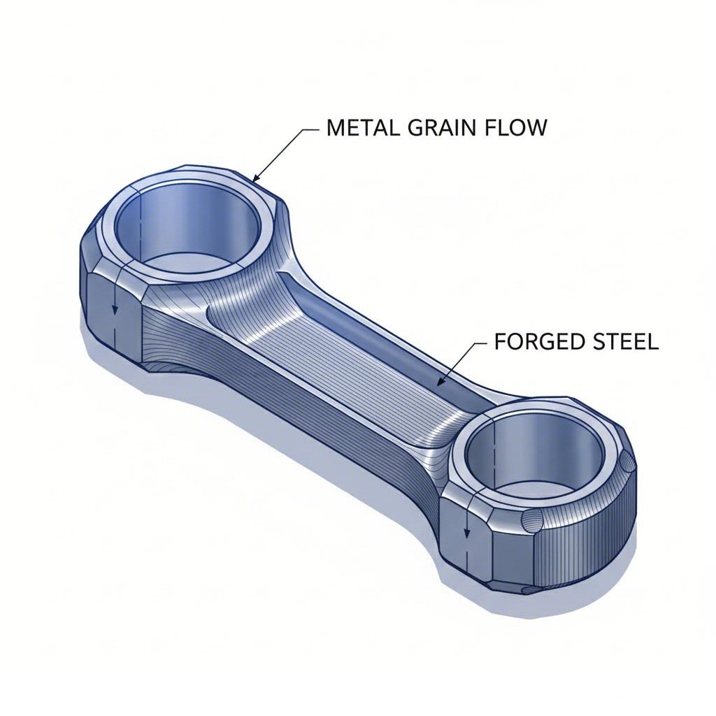
Forged con rods represent an entirely different approach. During forging, a solid steel billet is heated and compressed under immense pressure—often exceeding 2,000 tons. This violent compression doesn't just shape the metal; it aligns the grain structure along the rod's length, following the contours of stress flow. Think of it like wood grain running along a baseball bat rather than across it. This aligned grain structure creates superior fatigue resistance precisely where high-RPM engines need it most.
The forging process also eliminates internal voids and porosity that weaken cast components. When your rod experiences 16,000 pounds of tension at TDC, those microscopic imperfections become crack initiation sites. Forged conrods simply don't have them.
Material Grade Hierarchy Explained
Selecting forged rods for high RPM isn't just about choosing "forged" over "cast." The specific alloy determines your safety margin and ultimate RPM capability. Here's how the material hierarchy breaks down:
- 4340 Chromoly Steel (40CrNiMoA): The baseline performance material. This nickel-chromium-molybdenum alloy offers excellent toughness and fatigue resistance at a reasonable cost. As noted by KingTec Racing, 4340 steel provides "an excellent balance between strength and weight," making it suitable for turbocharged street builds through moderate race setups. Typical threshold: 7,000-8,500 RPM depending on application.
- 300M Steel: An aerospace-grade evolution of 4340 with added silicon and vanadium. These additions dramatically increase tensile strength and fatigue resistance—critical for sustained high-RPM operation. 300M forged rods handle high-boost, high-RPM engines and endurance racing applications where 4340 reaches its limits. Typical threshold: 8,500-10,000+ RPM.
- Titanium: When every gram matters, titanium delivers an unmatched strength-to-weight ratio. Reducing reciprocating mass means lower inertia forces at high RPM, allowing engines to rev faster and respond quicker. However, titanium's premium cost and limited suitability for street use restrict it to specialized racing applications. Best for: professional motorsports where weight savings justify the investment.
- Billet connecting rods: Machined from solid aluminum or steel blocks, these offer extreme customization for unique applications. Aluminum billet rods excel in drag racing—absorbing shock loads during short, violent runs—but their lower fatigue life makes them unsuitable for endurance or street use.
Understanding this hierarchy matters because material selection directly influences how your rods handle the tension-compression cycles that define high-RPM operation. During the exhaust stroke at 9,000 RPM, your piston decelerates from roughly 4,000 feet per minute to zero, then accelerates back downward—all within milliseconds. The connecting rod must absorb this tension load without stretching, distorting, or cracking. Choosing the right material grade for your RPM target isn't overkill; it's engineering.
I-Beam vs H-Beam Rod Design Selection
You've selected the right material grade for your RPM target—but you're only halfway there. The beam design of your connecting rods determines how that material performs under load. When comparing connecting rods I-beam vs H-beam, the answer isn't universal. It depends entirely on your engine's characteristics, aspiration method, and power delivery.
I-Beam Rods for Lightweight High-Revving Builds
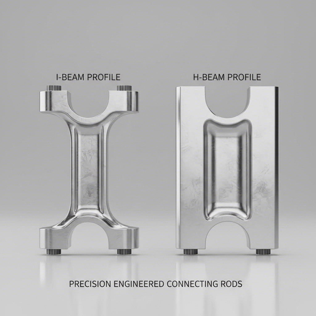
Look at any factory engine rods, and you'll likely find an I-beam design. Named for its capital "I" cross-section profile, this configuration features two wide flanges connected by a thinner web section. But don't let their stock application fool you—high-performance I-beam connecting rods are the go-to choice for serious power.
What makes I-beams excel in high-RPM applications? The answer lies in their strength orientation. According to Manley Performance, their Pro Series I-beam connecting rods are "designed to withstand four-digit horsepower numbers and extreme engine loads commonly encountered with power adders." The I-beam's geometry creates natural gussets from the pin bore to the center section, providing exceptional compression strength.
Here's why that matters for boosted engines: when combustion pressure slams down on the piston during the power stroke, the connecting rod experiences tremendous compression loading. The I-beam's design resists this force without the center section bowing or deflecting. Under heavy compression loads, the sides of an I-beam can't expand outward—they're inherently constrained by the geometry.
I-beam engine rods also tend to be narrower at the big end, which provides critical clearance for stroked crankshafts. If you're running a stroker combination pushing 8,000+ RPM, that extra clearance could be the difference between a screaming engine and scattered parts.
H-Beam Advantages in Forced Induction Applications
Wait—didn't we just say I-beams handle compression loads better? Here's where the confusion begins, and where understanding your specific application becomes critical.
H-beam rods feature a profile resembling a steel construction beam: two wide, flat faces connected by a thinner bridge. This design was originally developed for WWII fighter planes after numerous rod failures from heavy nitrous oxide use. The H-beam's strength advantage lies in its lightweight construction and tensile load handling at the piston end.
According to Speedway Motors, H-beam rods are "easier to lighten than an I-beam, making them better suited for high-revving applications." When every gram of reciprocating mass translates to reduced inertia forces at high RPM, that weight advantage matters. Less mass means lower tensile loads on the rod at TDC—exactly where high-RPM engines experience maximum stress.
For naturally aspirated builds chasing 9,000+ RPM, or nitrous applications where shock loading at the piston end is severe, H-beams offer an excellent strength-to-weight ratio. They're also generally more affordable since they require less machining during manufacturing.
Making the Right Choice: RPM and Power Considerations
So which design should you choose? The piston and connecting rod combination in your engine will dictate the answer based on these factors:
| Characteristic | I-Beam Connecting Rods | H-Beam Connecting Rods |
|---|---|---|
| Weight | Generally heavier | Typically 10-15% lighter |
| Primary Strength | Superior compression resistance | Excellent tensile load handling |
| Big End Profile | Narrower (better stroker clearance) | Wider profile |
| Ideal For | Boosted/supercharged, high-torque combinations | High-revving NA, nitrous applications |
| RPM Sweet Spot | 7,000-9,000+ RPM with boost | 8,000-10,000+ RPM naturally aspirated |
| Horsepower Range | 750-1,600+ HP (drag racing applications) | 600-1,200 HP (varies by bolt selection) |
| Cost | Higher (more machining required) | More affordable |
| Best Material Pairing | 4340 or 300M steel | 4340 steel or aluminum billet |
Here's the reality that confuses even experienced builders: modern manufacturing has blurred the lines between these designs. As Speedway Motors notes, "the build materials and overall design is far more important than I-beam or H-beam. You will find both styles in every kind of street or race engine build; even F1 engines use both styles."
The takeaway? Don't obsess over beam design in isolation. Consider your complete combination—RPM target, boost level, intended use, and budget. A well-designed H-beam from a quality manufacturer will outperform a poorly-executed I-beam every time. With beam design understood, the next critical dimension to consider is rod length and how it affects piston dynamics at high RPM.
Rod Length and Ratio Considerations for High RPM
You've selected your material and beam design—but there's another variable hiding in plain sight that dramatically affects high-RPM performance. The length of your piston rods relative to crankshaft stroke creates geometric relationships that influence everything from piston side loading to cylinder filling efficiency. Get this wrong, and even the best forged rods won't deliver optimal results.
Rod Ratio Calculations for Performance Optimization
What exactly is rod ratio? According to HP Academy, it's simply the connecting rod length divided by crankshaft stroke. For example, a standard Mitsubishi 4G63 uses a 150mm connecting rod with piston and an 88mm stroke, yielding a rod ratio of 1.70.
Why does this number matter for high-RPM applications? The rod ratio directly controls the angulation between your connecting rod and crankshaft throughout each rotation. When you increase rod length while keeping stroke constant, this angulation decreases. That geometric change triggers a cascade of performance effects.
Here's what the numbers typically look like across different engine types, according to Engine Builder Magazine:
- Four-cylinder engines: 1.5 to 1.7 rod ratio range
- V6 engines: 1.7 to 1.8 rod ratio range
- V8 engines: 1.7 to 1.9 rod ratio range
- High-RPM race engines: 1.8+ rod ratio preferred
Some builders consider anything above 1.55 acceptable, but for serious high-RPM builds, pushing toward the higher end of these ranges offers measurable benefits. The question becomes: what are you willing to trade to get there?
How Rod Length Affects Piston Dwell Time
Imagine your piston approaching top dead center at 9,000 RPM. With a shorter connecting rod, it rockets through TDC and immediately begins accelerating downward. With a longer rod? The piston lingers near TDC slightly longer—a phenomenon called "dwell time."
This increased dwell creates two significant advantages for high-RPM performance. First, it improves cylinder filling at elevated engine speeds. When the piston spends more time near TDC during the intake stroke, the intake valve has additional time to flow air into the cylinder before the piston begins its descent. At 8,000+ RPM, every fraction of a degree matters for volumetric efficiency.
Second, longer dwell time allows combustion pressure to act on the piston for a greater portion of the power stroke. As HP Academy explains, peak torque production occurs around 16-18 degrees after TDC—precisely when you want maximum mechanical advantage transferring through the rods in engine to the crankshaft. Accelerating more slowly away from TDC means more pressure pushing down during this critical window.
But here's the trade-off most builders overlook: lower rod ratios actually improve low-RPM performance. Shorter rods accelerate the piston faster away from TDC, creating higher vacuum in the cylinder at lower engine speeds. This promotes better airflow and fuel atomization during everyday driving. That's why production engines often run moderate rod ratios—they're optimizing for the entire RPM range, not just peak power.
Piston Side Loading and Wear Considerations
Beyond dwell time, rod ratio directly affects how hard your pistons push against the cylinder walls. With a lower rod ratio, the connecting rod sits at a steeper angle during mid-stroke, forcing the piston harder into the bore. This increased thrust loading accelerates wear on piston skirts and cylinder walls while generating additional friction.
For high-RPM applications where rods in engine experience thousands of cycles per minute, reduced side loading translates to less heat generation and longer component life. Engines running sustained high RPM—road racing, time attack, endurance events—particularly benefit from higher rod ratios that minimize this friction penalty.
Key Considerations When Selecting Rod Length
Before ordering longer rods for your build, consider these critical factors:
- Block deck height: Longer rods require either a taller block or a piston with reduced compression height to prevent the piston from protruding above the deck at TDC
- Piston design changes: Moving the wrist pin higher in the piston accommodates longer rods but may intersect the oil control ring—requiring rail support modifications
- Available rod lengths: Off-the-shelf options vary by platform; custom rods expand possibilities but increase cost significantly
- RPM target vs. street manners: Higher rod ratios sacrifice some low-speed throttle response for high-RPM gains—acceptable for dedicated race engines but potentially frustrating for street-driven builds
- Stroker combinations: Increasing stroke automatically reduces rod ratio unless you compensate with longer rods; a 383 stroker with stock 5.7-inch SBC rods drops to a 1.52 ratio
The reality, as Engine Builder Magazine notes, is that "there is no 'best' rod ratio for any given engine." A BMW M3 with a seemingly low 1.48 ratio still produces 2.4 horsepower per cubic inch. Cylinder head flow, cam timing, and intake design often overshadow rod ratio effects. However, when optimizing every variable for high-RPM performance, selecting the longest rods your combination can accommodate tilts the odds in your favor. With geometry understood, the next step is matching your rod selection to specific RPM thresholds and engine platforms.
RPM Threshold Guidelines and Platform Matching
You've absorbed the theory—material grades, beam designs, rod ratios. Now comes the practical question every builder asks: at what RPM should I upgrade, and what exactly should I upgrade to? This section eliminates the guesswork by providing specific threshold recommendations organized around three distinct performance tiers.
RPM Threshold Tiers and Upgrade Timing
Stock connecting rods engine manufacturers install are engineered for factory power levels and RPM limits. Push beyond these boundaries, and you're operating outside the safety margin those components were designed for. Here's how to match your rod selection to your actual RPM targets:
| RPM Tier | Material Recommendation | Rod Design | Fastener Spec | Typical Applications |
|---|---|---|---|---|
| 7,000-8,000 RPM | 4340 Chromoly Steel | I-beam or H-beam (application dependent) | ARP 8740 or equivalent | Mild street/strip builds, naturally aspirated performance, moderate boost |
| 8,000-9,000 RPM | Premium 4340 or Entry 300M | H-beam preferred for NA; I-beam for boosted | ARP 2000 or L19 | Serious street/strip, road racing, high-boost turbo builds |
| 9,000+ RPM | 300M Steel or Titanium | Application-specific; weight optimization critical | ARP Custom Age 625+ or equivalent | Professional motorsports, endurance racing, all-out competition |
Notice how fastener specifications escalate with each tier? That's intentional. Motor rods don't fail in isolation—rod bolts often become the weak link before the beam itself stretches or cracks. At 8,000+ RPM, specifying ARP 2000 fasteners isn't optional; it's mandatory for survival.
The 7,000-8,000 RPM tier represents the entry point for most performance builds. If you're building a weekend warrior that occasionally sees redline, quality 4340 forged rods with proper fasteners provide excellent insurance at reasonable cost. Many builders upgrade at this level simply for peace of mind—even if stock rods might theoretically survive, the consequences of failure far outweigh the component investment.
Push into the 8,000-9,000 RPM range, and you're entering territory where material quality becomes non-negotiable. Premium heat treatment, tighter dimensional tolerances, and superior fastener hardware separate surviving engines from scattered ones. This tier demands rods specifically designed for sustained high-RPM operation—not just capable of reaching those speeds occasionally.
Above 9,000 RPM? You're in race-spec territory where every component choice matters. Titanium rods reduce reciprocating mass significantly, lowering the inertia forces that become dominant at these speeds. Custom rod lengths, optimized rod ratios, and application-specific beam designs become standard practice. Budget considerations take a backseat to reliability.
Platform-Specific Rod Requirements
Different engine families present unique challenges when selecting forged rods. Here's what you need to know about three of the most popular high-RPM platforms:
LS Platforms (LS1/LS2/LS3/LS7): The SBC connecting rod legacy continues with LS engines, though factory rods vary significantly by variant. LS7 titanium rods from the Corvette Z06 handle 7,000+ RPM reliably in stock form—making them popular swaps for other LS builds. For serious power beyond 600 HP or sustained RPM above 7,500, aftermarket 4340 forged rods with ARP 2000 hardware become the standard upgrade path. The 6.098-inch stock rod length works well for most combinations, though stroker builds may benefit from 6.125-inch options.
Honda B/K Series: These engines were born to rev. Factory B18C5 rods survive 8,400 RPM stock redlines, but K-series builds pushing 9,000+ RPM demand forged replacements. The K24's 152mm rod length provides an excellent 1.78 rod ratio with the 85.5mm stroke—nearly ideal for high-RPM applications. Most builders specify H-beam designs here since naturally aspirated Honda builds prioritize weight reduction for maximum rev capability. For boosted K-series combinations, switching to I-beam designs provides additional compression strength without sacrificing much high-RPM potential.
Toyota 2JZ: The legendary 2JZ-GTE handles impressive power on stock rods—1,000+ HP builds exist using factory components. However, those rods were designed for the stock 6,800 RPM redline. Pushing beyond 7,500 RPM, especially with significant boost, requires aftermarket forged replacements. The 2JZ's 142mm rod length with 86mm stroke yields a 1.65 ratio—adequate but not exceptional for extreme RPM. Most builders selecting forged rods for 2JZ applications choose I-beam designs in 4340 steel when boost pressure exceeds 25 PSI or power targets surpass 800 HP.
Regardless of platform, remember that rod selection doesn't happen in isolation. Your rotating assembly must be balanced as a complete unit—crankshaft, rods, pistons, and fasteners working together. Upgrading only the connecting rods without verifying compatibility with existing components creates new failure points rather than eliminating them. Understanding how rods fail at high RPM helps you prevent those failures entirely.
Failure Mode Analysis and Prevention Strategies
You've selected premium materials, chosen the right beam design, and matched your rods to your RPM targets. But here's the uncomfortable truth: even the best connecting rod in engine applications will fail if you don't understand how failure actually occurs. Knowing what do connecting rods do under stress—and where they break down—transforms your approach from hopeful installation to engineered reliability.
Common High-RPM Failure Modes Explained
Connecting rods don't simply "break." They fail in predictable patterns based on the specific loads they encounter. Understanding these failure modes helps you prevent them before your engine becomes an expensive paperweight.
According to BoostLine Products, rods engine failures typically stem from five primary causes—each preventable with proper selection and installation:
- Rod stretch from tensile loads at TDC: At high RPM, the piston and rod assembly decelerates violently at top dead center during the exhaust stroke. This creates tremendous tensile loading that literally stretches the rod. Repeated stretch cycles eventually cause fatigue cracking, typically initiating near the big-end bore. Prevention: select rods rated for your actual RPM target with appropriate safety margin.
- Big-end bore distortion: When tensile loads repeatedly stretch the rod, the big-end bore gradually becomes oval-shaped. This "egg-shaping" squeezes out the oil film between the bearing and crankshaft journal, causing metal-on-metal contact. The result? Bearing spin, catastrophic heat generation, and potential rod separation. Prevention: proper material grade selection and correct bearing clearances.
- Small-end failures: The wrist pin bore experiences both tensile and compressive loading with every engine cycle. At sustained high RPM, inadequate small-end design leads to cracking around the pin bore or bushing failure. Prevention: verify your rods feature properly sized and bushed small ends for your power level.
- Improper bearing clearance: Clearances that are too tight cause insufficient lubrication and excessive friction. Too loose? The crankshaft expels excess oil, causing pressure loss and metal-on-metal contact. Either scenario accelerates wear and can destroy rods and crank alike. Prevention: use precise measuring techniques and follow manufacturer specifications exactly.
- Detonation damage: Engine knock sends shockwaves through rods engine components, creating stress loads they weren't designed to handle. The rapid pressure spikes from detonation can bend or break even quality forged rods. Prevention: proper tuning, adequate fuel octane, and appropriate ignition timing.
Rod bolts are often considered the single most important fasteners in the engine—they experience the greatest stress from a reciprocating load standpoint and must withstand tremendous forces created by the piston and connecting rod in motion.
Rod Bolt Selection and Torque Specifications
Here's what experienced engine builders know that novices learn the hard way: rod bolts fail more often than the rods themselves. When you're spinning an engine to 8,500 RPM, those fasteners cycle through 140+ tension-compression events per second. They're the only thing preventing the rod cap from slinging off the end of the connecting rod at incredible speeds.
According to BoostLine's technical guide, rod bolt selection must match your power output and operating conditions. Stock fasteners in everyday engines simply aren't designed for high-performance abuse. High-strength bolts made from superior materials with specialized coatings provide the fatigue resistance that sustained high-RPM operation demands.
But selecting quality bolts is only half the equation. Installation determines whether those bolts protect your engine or become the failure point:
Why bolt stretch measurement matters more than torque specs:
Your torque wrench might read 45 ft-lbs, but is that actually achieving the correct clamping force? Different torque wrenches produce different results—your Pittsburgh may not read the same as someone else's Snap-on. That's why professional engine builders use rod bolt stretch gauges to verify proper installation.
Bolt stretch is simply the amount of length a bolt extends when load is applied. Think of fasteners like springs: stretch them within their designed limits repeatedly, and they perform flawlessly. Exceed their yield point? They overstretch and fail—just like a spring pulled too far won't return to its original shape.
The stretch measurement process:
For ARP 2000 connecting rod bolts with a recommended torque of 45 ft-lbs, the expected stretch might be .0055"-.0060". The procedure works like this: apply the recommended assembly lube to threads and bolt head underside, install the bolt hand-tight, zero your stretch gauge on the relaxed bolt, then torque to just below specification. Measure the stretch—if it's under the minimum, tighten further until you're within spec.
An under-stretched rod bolt can back off during operation, killing your engine instantly. Being just 5-10 ft-lbs under specification creates potential for catastrophic failure once the engine runs.
Assembly lubricant matters:
The lubricant used during torquing dramatically affects the force actually applied. Conventional 30W engine oil breaks down over time, reducing your initial preload. Purpose-built assembly lubes like ARP Ultra-Torque maintain consistent clamping force throughout the fastener's service life. If you're building for sustained high-RPM operation, this detail isn't optional—it's essential.
With failure modes understood and prevention strategies in place, you're ready to consolidate everything into a practical selection framework you can apply to your specific build.
Building Your Rod Selection Decision Framework
You've absorbed the metallurgy, compared beam designs, calculated rod ratios, and studied failure modes. Now it's time to transform that knowledge into action. This framework consolidates everything into a systematic process you can apply to your specific engine connecting rods selection—no more guesswork, just engineering.
Your Rod Selection Checklist
Selecting the right connecting rods and pistons combination requires evaluating multiple variables in sequence. Skip a step, and you risk ordering components that don't work together—or worse, fail under load. Follow this process from start to finish:
- Determine your actual target RPM: Be honest here. What RPM will your engine regularly see—not occasionally touch? A weekend drag car that briefly hits 8,000 RPM has different requirements than a road racing engine holding 8,500 RPM for 20-minute sessions. Your sustained operating range dictates material and fastener requirements more than peak numbers.
- Identify power output and boost levels: A 500 HP naturally aspirated build stresses rods differently than a 500 HP turbocharged combination. Boosted applications multiply cylinder pressure dramatically, demanding superior compression strength. Document your target horsepower, torque peak, and maximum boost pressure before proceeding.
- Select the appropriate material grade: Match your material to your RPM tier. For 7,000-8,000 RPM applications, quality 4340 chromoly provides excellent durability at reasonable cost. Pushing 8,000-9,000 RPM? Premium 4340 with superior heat treatment or entry-level 300M becomes appropriate. Above 9,000 RPM demands 300M or titanium—no exceptions.
- Choose your beam design: Reference your power delivery method. Boosted or high-torque combinations generally favor I-beam designs for compression strength. Naturally aspirated screamers and nitrous applications often benefit from lighter H-beam configurations. Remember: quality matters more than beam style—a premium H-beam outperforms a budget I-beam every time.
- Verify rod length compatibility: Check your block deck height, piston compression height, and available rod lengths for your platform. Longer rods improve high-RPM characteristics but require shorter pistons or taller blocks. Confirm your complete package fits before ordering.
- Specify fastener requirements: Rod bolts must match your RPM tier. ARP 8740 works for entry-level builds; ARP 2000 becomes mandatory above 8,000 RPM. Extreme applications require L19 or Custom Age 625+ fasteners. Never reuse stretched or questionable hardware.
- Confirm balancing requirements: Every rod in engine assemblies must be weight-matched. Specify your balancing tolerance—typically within 1 gram for performance builds, 0.5 grams for race applications. Your machine shop needs this information before assembly.
Working with Manufacturers for Custom Specifications
Off-the-shelf rods work for most builds, but unique combinations often require manufacturer collaboration. When standard catalog options don't fit your requirements, here's how to approach custom specifications:
Prepare complete documentation: Manufacturers need specific dimensions—center-to-center length, big-end bore diameter, small-end bore size, and any clearance requirements for your specific block and crankshaft. Measure twice; order once. Incorrect specifications result in expensive paperweights.
Communicate your application clearly: A rod designed for drag racing handles different loading than one built for endurance events. Specify your use case, expected RPM range, power level, and whether the engine sees sustained high-RPM operation or brief bursts. This information helps manufacturers recommend appropriate beam thickness, material grade, and fastener specifications.
Verify machine shop compatibility: Your engine builder needs rods that arrive ready for installation—or at least close to it. Confirm whether the manufacturer supplies rods requiring additional machine work, and ensure your shop has the capability to perform any necessary finishing operations.
Request documentation: Quality manufacturers provide material certifications, dimensional inspection reports, and installation specifications. These documents prove the rods meet advertised specifications and provide critical torque values for your specific fasteners. If a manufacturer can't provide documentation, reconsider your source.
The difference between a successful high-RPM build and a scattered engine often comes down to these details. Taking time to properly specify your connecting rods—rather than simply ordering the most expensive option and hoping for the best—is the difference between engineering and gambling. With your selection framework complete, the final step is sourcing components from manufacturers who can deliver the quality your build demands.
Sourcing Quality Forged Rods from Certified Manufacturers
You've engineered your selection—material grade, beam design, rod length, fastener specs. Now comes the question that separates successful builds from frustrating failures: where do you actually source high performance connecting rods that meet your specifications? The manufacturer you choose determines whether your carefully planned combination delivers race-day reliability or becomes an expensive lesson in cutting corners.
Quality Certifications That Matter for Performance Parts
Not all forging operations produce equal results. When you're trusting connecting rods to survive 8,500 RPM and 1,000+ horsepower, manufacturing consistency isn't optional—it's survival. This is where industry certifications become your first filter for potential suppliers.
IATF 16949 certification represents the gold standard for automotive component manufacturing. According to Meadville Forging Company, this international standard "emphasizes continual improvement, defect prevention and reduction of variation and waste." For forged racing rods, that translates directly to dimensional consistency, proper heat treatment, and reliable material properties across every unit produced.
Why does this matter for your build? Imagine ordering a set of custom connecting rods, only to discover they're 0.003" out of spec on the big-end bore. That variation—invisible without precision measurement—creates uneven bearing crush and potential failure under load. IATF 16949 certified manufacturers implement statistical process control (SPC) and real-time quality monitoring that catches such variations before components ship.
Look for manufacturers demonstrating:
- Material traceability: Documentation proving the steel alloy meets advertised specifications from raw billet through finished product
- Dimensional inspection reports: Measurements confirming critical dimensions fall within tolerance for every production run
- Heat treatment verification: Records proving proper hardening cycles that develop the grain structure performance forging promises
- Shot peening certification: Documentation of surface treatment processes that enhance fatigue resistance
Manufacturers earning OEM supplier awards—like Ford's Q1 designation or GM Supplier Quality Excellence recognition—have proven their quality systems under the most demanding production requirements. These credentials indicate processes robust enough for max speeding rods destined for professional motorsports applications.
From Prototype to Production
What if catalog options don't match your unique combination? Perhaps you're building a stroker with non-standard rod length requirements, or your cylinder head swap demands different big-end dimensions. Custom connecting rods become necessary—and lead time suddenly matters.
Traditional custom rod manufacturing often requires 8-12 weeks from order to delivery. For racers facing season deadlines or builders with customers waiting, that timeline creates real problems. This is where manufacturer capabilities diverge significantly.
Modern precision forging operations like Shaoyi (Ningbo) Metal Technology have compressed this timeline dramatically. With IATF 16949 certification and in-house engineering capabilities, they deliver rapid prototyping in as little as 10 days—transforming custom specifications into physical components you can test-fit and validate before committing to production quantities.
When evaluating manufacturing partners for custom rods, consider these factors:
- Engineering support: Can they review your specifications and identify potential issues before production? In-house engineering prevents costly revisions after parts arrive.
- Prototyping capability: Single-unit or small-batch production allows validation before committing to full sets. This catches fitment issues early.
- Production scalability: If you're building multiple engines or developing a product line, can the manufacturer scale from prototype to volume production seamlessly?
- Geographic considerations: Manufacturers located near major shipping ports—like Ningbo, China—often provide faster international delivery and streamlined logistics.
The relationship between prototyping speed and final quality isn't contradictory when proper processes exist. Hot forging operations with advanced die technology and real-time process monitoring produce consistent results whether running one prototype or one thousand production units.
Making Your Final Decision
Selecting forged rods for high RPM applications ultimately comes down to matching your requirements with manufacturers capable of meeting them. Budget constraints are real—but so are the consequences of rod failure at 9,000 RPM. The cheapest option rarely represents the best value when engine rebuilds cost five figures.
Request quotes from multiple certified manufacturers. Compare not just price, but included documentation, fastener quality, and warranty terms. Ask for references from builders running similar power levels and RPM targets. The extra research investment pays dividends when your engine survives conditions that would scatter lesser components.
You've moved beyond guessing—you're engineering. Apply the framework from this guide, source from qualified manufacturers, and build with confidence. Your high-RPM combination deserves components selected through systematic analysis, not hopeful assumptions.
Frequently Asked Questions About Selecting Forged Rods for High RPM
1. What is the best rod for high-RPM applications?
The best rod for high-RPM depends on your specific application. For naturally aspirated engines revving above 8,000 RPM, H-beam rods offer excellent strength-to-weight ratios since they're easier to lighten. For boosted or high-torque combinations at high RPM, I-beam rods provide superior compression strength. Material matters equally—4340 chromoly steel suits 7,000-8,500 RPM builds, while 300M steel or titanium becomes necessary for sustained operation above 9,000 RPM. Quality manufacturers with IATF 16949 certification ensure consistent performance across all units.
2. At what RPM should I upgrade from stock to forged connecting rods?
Consider upgrading to forged rods when regularly operating above 7,000 RPM or when power levels exceed your engine's stock design limits. The 7,000-8,000 RPM range represents the entry tier for forged upgrades with 4340 steel rods. Between 8,000-9,000 RPM, premium forged rods with ARP 2000 hardware become mandatory. Above 9,000 RPM, race-spec 300M steel or titanium rods are essential. For boosted applications, upgrade thresholds may be lower due to increased cylinder pressures.
3. What's the difference between I-beam and H-beam connecting rods?
I-beam rods feature a capital 'I' cross-section with natural gussets providing exceptional compression resistance—ideal for boosted engines handling heavy combustion loads. H-beam rods have two flat faces connected by a thinner bridge, making them lighter and easier to machine. This weight advantage reduces inertia forces at high RPM, making H-beams preferable for naturally aspirated high-revving builds and nitrous applications. Modern quality manufacturing has narrowed performance gaps, making material grade and fastener selection equally important as beam design.
4. How does rod ratio affect high-RPM engine performance?
Rod ratio (rod length divided by stroke) influences piston dwell time at TDC and side loading. Higher rod ratios (1.8+) increase piston dwell time, improving cylinder filling at high RPM and allowing combustion pressure to act longer during the power stroke. They also reduce piston side loading, minimizing friction and wear during sustained high-RPM operation. However, higher ratios may sacrifice low-RPM throttle response. Most high-RPM race engines target the upper end of their platform's typical ratio range.
5. Why are rod bolts so critical in high-RPM applications?
Rod bolts experience the greatest reciprocating stress in the engine—cycling through 140+ tension-compression events per second at 8,500 RPM. They're the only fasteners preventing rod cap separation at extreme speeds. Stock bolts aren't designed for high-performance abuse. ARP 8740 bolts suit entry-level builds, while ARP 2000 becomes mandatory above 8,000 RPM. Proper installation requires measuring bolt stretch rather than relying solely on torque values, as an under-stretched bolt can back off during operation and cause catastrophic failure.