 Small batches, high standards. Our rapid prototyping service makes validation faster and easier —

Mastering Precision: The Role of CAD in Automotive Die Design

TL;DR
Computer-Aided Design (CAD) is an essential technology in modern automotive die design. It empowers engineers to create, simulate, and refine highly precise 3D digital models of manufacturing dies. This process is critical for ensuring accuracy, optimizing the performance of complex components through virtual testing, and significantly accelerating the entire development lifecycle from concept to production.
The Foundational Role of CAD in Achieving Precision and Complexity
At its core, the role of CAD in automotive die design is to translate abstract engineering concepts into precise, detailed, and functional digital blueprints. Before any metal is cut, CAD software serves as the virtual workbench where every surface, curve, and tolerance of a die is meticulously crafted. This digital-first approach has replaced traditional manual drafting, introducing a level of accuracy and complexity that was previously unattainable. It allows designers to create intricate die geometries that must comply with the automotive industry's stringent specifications.
The primary function of CAD is the creation of 2D drawings and, more importantly, 3D solid models. These models are not just visual representations; they are data-rich assets containing exact geometric information. This ensures that every component of the die—from the main cavity to the smallest alignment pin—is designed to function perfectly within the larger assembly. Unlike manual methods, CAD allows for rapid modifications. If a design flaw is found or an improvement is conceptualized, engineers can adjust the model in minutes, rather than spending days redrawing blueprints.
This digital precision ensures that the virtual model is a perfect representation of the final physical product. It eliminates the guesswork and reduces the potential for human error that plagued manual design processes. The ability to model complex, free-form surfaces is particularly crucial in the automotive sector, where both aesthetic appeal and aerodynamic performance are paramount. This capability is foundational to producing the high-quality, reliable vehicles consumers expect.
Key capabilities that CAD brings to the initial design phase include:
- Complex Geometry Creation: Designers can model highly intricate and organic shapes for components like body panels and interior fixtures, which would be nearly impossible to draft by hand.
- Component Compatibility Assurance: By assembling virtual parts, engineers can verify fit and clearance, preventing interference issues long before manufacturing begins.
- Detailed Blueprint Generation: CAD models are used to automatically generate the detailed 2D drawings and documentation required for the manufacturing floor.
- Material Specification: Designs can incorporate specific material properties, allowing for more accurate analysis and simulation in later stages.
Core CAD Capabilities: From 3D Modeling to Performance Simulation
Beyond basic modeling, advanced CAD platforms provide a suite of powerful tools for validating and optimizing die designs. The most critical of these are 3D modeling and virtual simulation, which allow engineers to not only visualize a component but also to test its real-world performance under a wide range of conditions. This virtual testing is a cornerstone of modern automotive development, saving immense time and resources by reducing the reliance on costly physical prototypes.
3D modeling allows for a complete visualization of every part of the die assembly. Engineers can rotate, section, and explode models to inspect every detail, ensuring the design is robust and manufacturable. This is where leading industry software like CATIA and Siemens NX excel, offering specialized toolsets for automotive applications. These platforms allow for both solid modeling (for structural parts) and surface modeling (for creating the high-quality, class-A surfaces of exterior body panels).
Performance simulation, often using Finite Element Analysis (FEA), is where the digital model is subjected to virtual stresses. Engineers can simulate the stamping process, analyzing how sheet metal will flow into the die, where stress points will occur, and if the material is at risk of tearing or wrinkling. This analysis helps optimize the die's design for durability, efficiency, and the quality of the final stamped part. These simulations can predict potential failures before any tooling is manufactured, preventing costly rework and production delays.
The following table breaks down key CAD functions and their benefits in die design:
| CAD Function | Description | Benefit in Die Design |
|---|---|---|
| Solid Modeling | Creating 3D objects with mass and volume, representing structural components. | Ensures structural integrity and accurate fit of all die components. |
| Surface Modeling | Defining the complex exterior curves of a part, focusing on aesthetics and aerodynamics. | Creates smooth, high-quality surfaces for vehicle body panels and trim. |
| Assembly Modeling | Virtually combining multiple components to check for interference and proper alignment. | Prevents costly manufacturing errors by ensuring all parts fit together correctly. |
| Engineering Simulation (e.g., FEA) | Simulating physical phenomena like stress, heat, and fluid flow on a digital model. | Predicts and mitigates potential failure points in the die or the stamped part. |
A simplified design and validation workflow typically follows these steps:
- Create a detailed 3D model of the die and the sheet metal part.
- Assemble the virtual components to simulate the complete tooling setup.
- Apply simulated forces, pressures, and material properties to replicate the stamping process.
- Analyze the simulation results for stress, material flow, and potential defects.
- Refine the 3D model based on the analysis and repeat the simulation until the design is optimized.
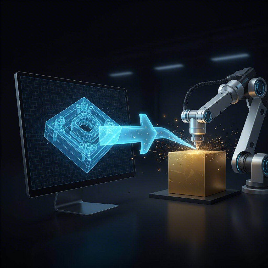
The Synergy of CAD/CAM: Bridging Digital Design and Physical Manufacturing
The role of CAD extends far beyond the design phase; it is the critical first step in the entire manufacturing process through its integration with Computer-Aided Manufacturing (CAM). The CAD/CAM synergy creates a seamless digital thread from the designer's screen to the physical machinery on the factory floor. This connection ensures that the immense precision achieved in the digital model is perfectly translated into the final physical die.
The workflow begins once the CAD model is finalized and approved. This geometric data is exported directly into CAM software. The CAM system then uses the 3D model as a blueprint to automatically generate the toolpaths—the precise coordinates and instructions that will guide CNC (Computer Numerical Control) machines. These machines, such as mills and lathes, cut the hardened tool steel to create the physical die components. This automated process is not only faster but also vastly more accurate than manual machining, eliminating human error from the fabrication process.
This integration is what enables the production of dies with incredibly complex geometries and tight tolerances, which are essential for modern vehicles. The benefits are substantial: production speed is dramatically increased, manual errors are virtually eliminated, and parts that would be too complex for manual machining become feasible. Companies that master this integrated workflow can deliver higher quality components with shorter lead times. For example, industry leaders in custom tooling, such as Shaoyi (Ningbo) Metal Technology Co., Ltd., leverage advanced CAD/CAM processes and CAE simulations to produce high-precision automotive stamping dies for major OEMs and Tier 1 suppliers, showcasing the power of this digital synergy in a real-world manufacturing environment.
To ensure a smooth transition from CAD to CAM, engineers focus on maintaining data integrity through standardized file formats (like STEP or IGES) and clear communication between design and production teams. This seamless data handoff is fundamental to modern, efficient manufacturing.

Innovation and Future Trends in Automotive Die Design CAD
Computer-Aided Design is not a static technology; it is constantly evolving, pushing the boundaries of what is possible in automotive engineering. The future of CAD in die design is being shaped by advancements in artificial intelligence, cloud computing, and immersive technologies. These innovations are transforming the role of the design engineer from a manual modeler into a design strategist who guides intelligent systems to achieve optimal outcomes.
One of the most significant emerging trends is generative design. In this process, engineers input a set of design constraints—such as material, weight limits, manufacturing method, and required strength—and an AI algorithm generates hundreds or even thousands of potential design solutions. The engineer can then evaluate these AI-proposed designs to find the most efficient and innovative option. This can lead to lighter, stronger parts that would be difficult for a human to conceptualize, directly contributing to vehicle fuel efficiency and performance.
Cloud-based CAD platforms are also revolutionizing collaboration. Global automotive teams, from designers in Germany to engineers in the United States and manufacturing experts in Japan, can now work on the same live model simultaneously. This real-time collaboration breaks down geographic barriers, accelerates decision-making, and ensures that all stakeholders are working with the most up-to-date information, drastically reducing version control errors and project delays.
Looking ahead, several key trends will continue to define the evolution of CAD in automotive die design:
- AI-Powered Design Suggestions: Software will increasingly offer intelligent recommendations to optimize designs for manufacturability, cost, and performance in real time.
- Real-Time Cloud Collaboration: Global teams will work seamlessly on centralized models, streamlining the development process from end to end.
- Integration with VR/AR: Engineers will use Virtual and Augmented Reality to conduct immersive design reviews, allowing them to visualize and interact with digital models at a 1:1 scale before production.
- Advanced Material Simulations: CAD tools will offer even more sophisticated simulations for new and composite materials, predicting their behavior with greater accuracy.
Frequently Asked Questions
1. What are the roles of CAD in design?
In design, CAD (Computer-Aided Design) serves several critical roles. It allows designers to create highly accurate 2D drawings and 3D models of products before they are manufactured. This digital format enables easy sharing, review, simulation, and modification of designs, which accelerates innovation and helps get products to market faster. It acts as the foundational blueprint for the entire product lifecycle.
2. Why is CAD useful in DT?
In Design and Technology (DT), CAD is incredibly useful because it allows for rapid prototyping and iteration. Designs can be quickly modified and tested virtually, saving the time and cost associated with building physical models for every iteration. It also helps in understanding complex concepts like stress analysis or material economy, as simulations can visualize how a product will behave under different conditions.
3. How can CAD help you as a future automotive technician?
For a future automotive technician, proficiency in CAD is a valuable skill. It allows you to understand vehicle design and construction at a fundamental level. With CAD models, you can visualize complex assemblies, understand how parts fit together, and diagnose problems more effectively. It also provides a basis for working with modern manufacturing technologies like 3D printing for custom parts or repairs, ensuring you are prepared for the increasingly digital nature of the automotive industry.