 Small batches, high standards. Our rapid prototyping service makes validation faster and easier —

Achieve Flawless Parts: Die Design for Optimal Material Flow

TL;DR
Effective die design for optimal material flow is a critical engineering discipline focused on creating a tool that ensures material forms smoothly, uniformly, and completely. Mastering this process is essential for preventing common manufacturing defects like cracking or wrinkling, minimizing material waste, and consistently producing high-quality components with precise, repeatable dimensions. Success hinges on a deep understanding of design parameters, material properties, and process controls.
Fundamental Principles of Material Flow in Die Design
At its core, die design is the bedrock of modern mass production, transforming flat sheets of metal into complex three-dimensional parts, from a car door to a smartphone casing. Material flow refers to the movement and deformation of this metal as it is shaped within the die. Optimal material flow is not merely a goal but a fundamental requirement for achieving high-quality, cost-effective manufacturing. It directly dictates the final part's precision, structural integrity, and surface finish. When flow is controlled and uniform, the result is a flawless component that meets exact tolerances. Conversely, poor flow leads to a host of expensive and time-consuming problems.
The entire discipline is guided by the philosophy of Design for Manufacturing and Assembly (DFMA), which prioritizes creating parts that can be produced efficiently and reliably. This expert mindset shifts the focus from simply designing a functional part to engineering a part that integrates seamlessly with the production process. A poorly designed die that restricts, tears, or unevenly stretches the material will invariably produce defective parts, leading to increased scrap rates, production delays, and potential tool damage. Therefore, understanding and controlling material flow is the first and most critical step in any successful die design project.
The contrast between good and poor material flow is stark. Good flow is characterized by the smooth, predictable, and complete filling of the die cavity. The material stretches and compresses exactly as intended, resulting in a finished part with uniform thickness and no structural weaknesses. Poor material flow, however, manifests as visible defects. If the material flows too quickly or without sufficient resistance, it can lead to wrinkling. If it is stretched too aggressively or caught on a sharp corner, it can tear or crack. These failures are almost always traceable to a fundamental misunderstanding or miscalculation of how the material will behave under pressure within the die.
Critical Design Parameters Controlling Material Flow
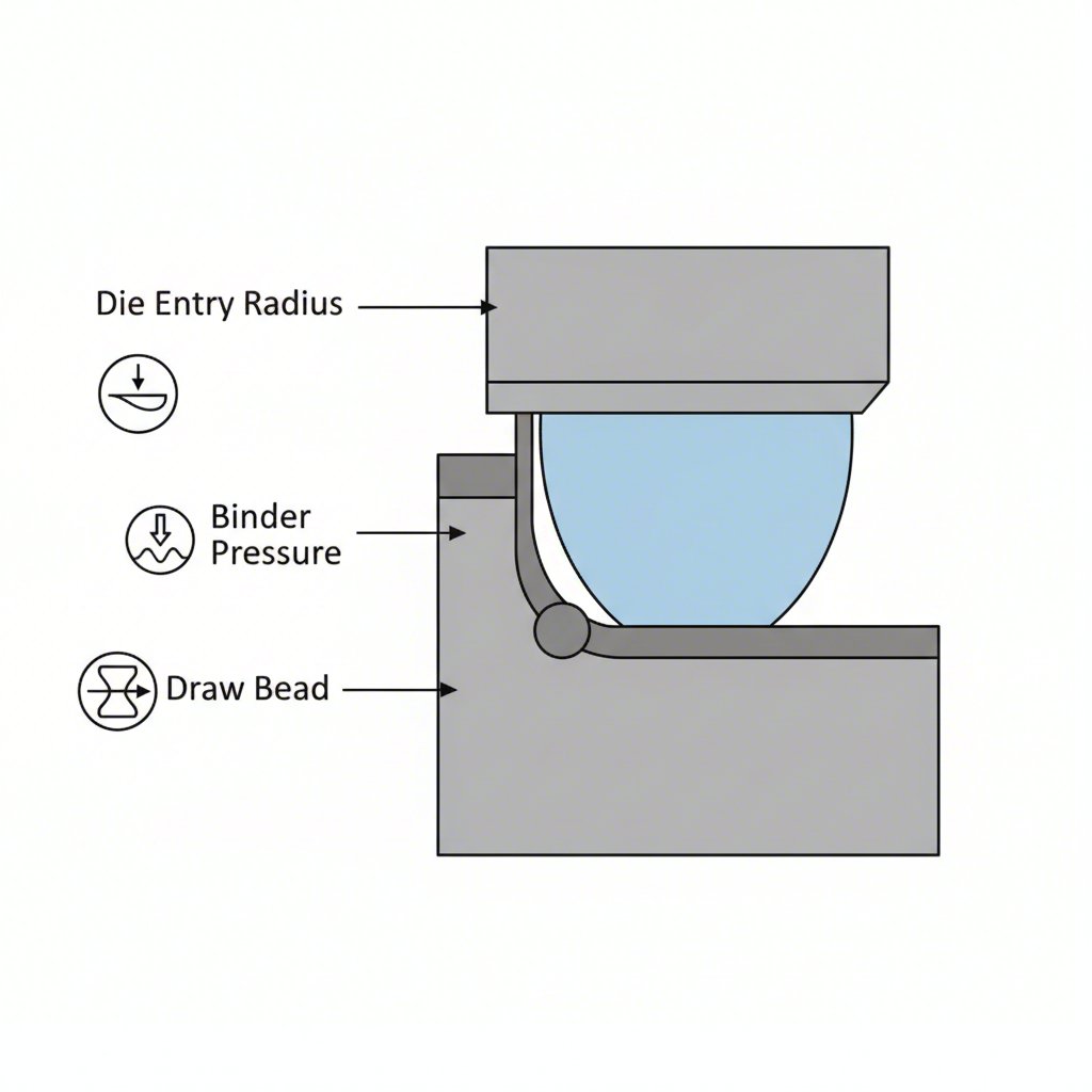
A designer's ability to achieve optimal material flow rests on the precise manipulation of key geometric features and process variables. These parameters act as the control levers for guiding metal into its final shape. In deep drawing processes, the die entry radius is paramount; a radius that is too small concentrates stress and causes tearing, while one that is too large allows material to move uncontrollably, leading to wrinkling. Similarly, binder pressure—the force holding the metal blank in place—must be perfectly calibrated. Too little pressure results in wrinkles, while too much restricts flow and can cause the part to fracture.
In extrusion processes, designers rely on different parameters to achieve the same goal of uniform flow. A primary tool is the bearing length, which is the length of the surface inside the die opening that the aluminum travels along. As detailed by experts at Gemini Group, longer bearing lengths increase friction and slow the material's flow. This technique is used to balance the exit velocity across the profile, ensuring thicker sections (which naturally want to flow faster) are slowed to match the speed of thinner sections. This prevents warping and distortion in the final extruded part.
Other critical parameters include the strategic use of draw beads in stamping, which are ridges on the binder surface that force the material to bend and unbend, adding resistance to control its entry into the die cavity. The press speed must also be carefully managed, as excessive speed can exceed the material's strain rate limit and cause tearing. The interplay of these factors is complex, and their application differs significantly between processes like stamping and extrusion, but the underlying principle remains the same: control resistance to achieve uniform movement.
| Design Parameter | Primary Effect on Material Flow | Common Application |
|---|---|---|
| Die Entry Radius | Controls stress concentration at the die opening. A small radius can cause tearing; a large radius can cause wrinkling. | Deep Draw Stamping |
| Bearing Length | Increases friction to slow down material flow in specific areas, ensuring uniform exit velocity. | Aluminum Extrusion |
| Binder Pressure | Applies force to the blank to prevent wrinkling and control the rate of material entry into the die. | Deep Draw Stamping |
| Draw Beads | Adds controlled resistance to material flow by forcing it to bend and unbend. | Stamping |
| Press Speed | Determines the rate of deformation. Excessive speed can lead to material tearing. | Stamping & Forging |
Material Properties and Their Impact on Flow
The selection of raw material establishes the fundamental rules and limitations for any die design. A material's intrinsic properties dictate how it will behave under the immense forces of forming, defining the boundaries of what is possible. The most critical property is ductility, or formability, which measures how much a material can stretch and deform without fracturing. Highly ductile materials like certain aluminum alloys or deep-drawing quality steel are forgiving and allow for the creation of complex shapes. In contrast, high-strength steels, while offering weight savings, are less ductile and require more generous bend radii and careful process control to prevent cracking.
Technical metrics such as the N value (work hardening exponent) and R value (plastic strain ratio) provide engineers with precise data on a material's formability. The N value indicates how well a metal strengthens as it is stretched, while the R value reflects its resistance to thinning during drawing. A deep understanding of these values is crucial for predicting material behavior and designing a die that works in harmony with the material, not against it.
When considering the best material for die making itself, durability and wear resistance are key. Tool steels, particularly grades like 1.2379, are a classic choice due to their hardness and dimensional stability after heat treatment. For applications involving extreme temperatures or stress, such as in die casting or high-volume forging, tungsten carbide is often used for its exceptional hardness and heat resistance. Ultimately, the choice of both the workpiece material and the die material involves a series of trade-offs between performance, formability, and cost. A designer must balance the desire for a lightweight, high-strength final part with the physical realities and costs of forming that material.
Leveraging Simulation and Technology for Flow Optimization
Modern die design has moved beyond the traditional trial-and-error approach, embracing advanced technology to predict and perfect material flow before any steel is cut. Computer-Aided Design (CAD) is the starting point, but the real optimization occurs through Finite Element Analysis (FEA) simulation software. Tools like AutoForm and Dynaform allow engineers to conduct a complete "virtual tryout" of the forming process. This software models the immense pressures, temperatures, and material behaviors within the die, creating a detailed digital prediction of how the metal will flow, stretch, and compress.
This simulation-driven approach provides invaluable foresight. It can accurately predict common defects such as wrinkling, cracking, springback, and uneven wall thickness. By identifying these potential failure points in the digital realm, designers can iteratively adjust die geometry—modifying radii, adjusting bead shapes, or altering binder pressure—until the simulation shows a smooth, uniform material flow. This predictive engineering saves enormous amounts of time and money by eliminating the need for costly and time-consuming physical prototypes and tool modifications.
Leading manufacturers now consider this technology an essential best practice for developing complex parts, particularly in demanding sectors like the automotive industry. For instance, companies specializing in high-precision components rely heavily on these simulations. As noted by Shaoyi (Ningbo) Metal Technology Co., Ltd., the use of advanced CAE simulations is fundamental to delivering top-tier automotive stamping dies for OEMs and Tier 1 suppliers, ensuring quality while reducing development cycles. This digital-first methodology represents a shift from reactive problem-solving to proactive, data-driven optimization, forming the cornerstone of efficient and reliable modern die design.
Common Failures Caused by Poor Material Flow and How to Avoid Them
Nearly all production failures in forming operations can be traced back to predictable and preventable issues with material flow. Understanding these common defects, their root causes, and their solutions is essential for any designer or engineer. The most frequent failures include cracking, wrinkling, and springback, each stemming from a specific flaw in the balance of forces and material movement within the die. A proactive, diagnostic approach can prevent these issues before they lead to costly scrap and downtime.
Cracking is a severe failure where the material is stretched beyond its elongation capacity and tears. This is often caused by design flaws such as an inside bend radius that is too small (a common rule is to keep it at least 1x the material thickness) or placing features like holes too close to a bend, which creates a stress concentration point. Wrinkling, on the other hand, occurs when there is an excess of material and insufficient pressure to hold it in place, causing it to buckle. This is typically a result of insufficient binder pressure or an overly large die entry radius that allows material to flow too freely.
Springback is a more subtle defect where the formed part partially returns to its original shape after being removed from the die due to elastic recovery. This can compromise dimensional accuracy and is particularly prevalent in high-strength materials. The solution is to calculate the expected springback and intentionally over-bend the part so it relaxes into the desired final angle. By systematically addressing the root causes of these failures, engineers can design more robust and reliable dies. The following provides a clear troubleshooting guide:
-
Problem: Cracking at a bend.
- Cause: The inside bend radius is too small, or the bend is oriented parallel to the material's grain direction.
- Solution: Increase the inside bend radius to at least the material's thickness. Orient the part so the bend is perpendicular to the grain direction for optimal formability.
-
Problem: Wrinkling in the flange or wall of a drawn part.
- Cause: Insufficient binder pressure is allowing uncontrolled material flow.
- Solution: Increase the binder pressure to adequately restrain the material. If necessary, add or modify draw beads to introduce more resistance.
-
Problem: Part dimensions are inaccurate due to springback.
- Cause: The material's natural elastic recovery was not accounted for in the die design.
- Solution: Calculate the anticipated springback and compensate by over-bending the part in the die. This ensures it springs back to the correct final angle.
-
Problem: Tearing or fracturing during the initial draw.
- Cause: The draw ratio is too aggressive, or lubrication is inadequate.
- Solution: Reduce the draw in the first stage and add subsequent stages if necessary. Ensure proper lubrication is applied to reduce friction and facilitate smooth material flow.
From Principles to Production: A Summary of Best Practices
Mastering die design for optimal material flow is a synthesis of science, technology, and experience. It begins with a foundational respect for the material's properties and the physical laws that govern its behavior under pressure. Success is not achieved by forcing a material into a shape, but by creating a pathway that guides it smoothly and predictably. This requires a holistic approach, where every design parameter—from the die entry radius to the bearing length—is carefully calibrated to work in concert.
The integration of modern simulation technologies like FEA has transformed the field, enabling a shift from reactive fixes to proactive optimization. By identifying and solving potential flow issues in a virtual environment, engineers can develop more robust, efficient, and cost-effective tooling. Ultimately, a well-designed die is more than just a piece of equipment; it is a finely tuned engine for production, capable of delivering millions of flawless parts with unwavering precision and quality.

Frequently Asked Questions
1. What is the die design rule?
While there isn't a single universal "rule," die design is governed by a set of best practices and principles. These include ensuring proper clearance between the punch and die, using generous bend radii (ideally at least 1x material thickness), maintaining adequate distance between features and bends, and calculating forces to prevent overloading the press. The overarching goal is to facilitate smooth material flow while ensuring the structural integrity of both the part and the tool.
2. What is the best material for die making?
The best material depends on the application. For most stamping and forming operations, hardened tool steels (like D2, A2, or grades such as 1.2379) are excellent choices due to their high strength, wear resistance, and toughness. For high-temperature processes like hot forging or die casting, or in extreme-wear scenarios, tungsten carbide is often preferred for its exceptional hardness and ability to retain strength at elevated temperatures. The selection always involves balancing performance requirements with cost.
3. What is a die design?
Die design is a specialized field of engineering focused on creating the tools, known as dies, used in manufacturing to cut, shape, and form materials like sheet metal. It is an intricate process that involves meticulous planning, precision engineering, and a deep understanding of material properties and manufacturing processes. The objective is to design a tool that can mass-produce a part to exact specifications with high efficiency, quality, and repeatability.