 Small batches, high standards. Our rapid prototyping service makes validation faster and easier —

Prototype CNC Services Decoded: From Quote to Perfect Part
What Prototype CNC Services Actually Deliver
Imagine you've spent months perfecting a design on your computer screen. The CAD model looks flawless, every dimension is calculated, and the simulations check out. But here's the question that keeps engineers up at night: will it actually work in the real world?
That's exactly where prototype CNC services come in. Unlike production machining—which focuses on churning out thousands of identical parts as efficiently as possible—CNC prototyping exists to transform your digital designs into physical parts you can hold, test, and refine before committing serious resources to full-scale manufacturing.
At its core, a CNC service for prototyping uses computer-controlled milling, turning, and related processes to produce small batches of parts quickly from production-grade materials. The goal isn't optimization or high-volume efficiency. It's learning. It's validation. It's catching design flaws before they become expensive production problems.
From CAD File to Physical Part in Days
Speed defines the prototype experience. While traditional manufacturing might require weeks of tooling preparation, precision CNC machining for prototypes can deliver finished parts in as little as 2-7 working days—sometimes even faster for simpler geometries. This rapid turnaround allows product teams to run multiple design iterations in the time it would take to receive a single batch through conventional methods.
The process is remarkably straightforward: you submit your CAD file, the shop programs the toolpaths, and CNC machines cut your part directly from solid metal or plastic stock. No expensive molds. No lengthy setup. Just your design, machined to specification.
Why Functional Prototypes Demand Real Machining
You might wonder why engineers don't simply 3D print everything during development. After all, additive manufacturing has become incredibly accessible. The answer lies in what CNC prototyping uniquely delivers: material authenticity.
When you need machined parts that will undergo real-world stress testing—thermal cycling, mechanical loads, sealing verification—you need parts made from the same aluminum, steel, or engineering plastics you'll use in production. CNC prototyping cuts from actual production-grade materials, so your tests reflect genuine performance characteristics. A 3D-printed bracket might look identical to the final design, but it won't tell you whether the actual aluminum version will survive repeated impacts or vibration.
Modern CNC machines routinely hold tolerances of ±0.005" (±0.127 mm) as standard, with precision work reaching ±0.001" or tighter when needed. This accuracy ensures your CNC parts fit together exactly as designed, allowing you to validate assembly interfaces and critical dimensions with confidence.
The Bridge Between Design and Production
Think of CNC prototyping as your design's proving ground. It supports you through every validation milestone:
- Concept verification – turning CAD ideas into tangible parts for team review and stakeholder feedback
- Engineering validation – confirming functions, interfaces, and performance under realistic conditions
- Design refinement – testing manufacturability and refining tolerances before production commitment
- Pilot production – building small batches that simulate production processes and assembly procedures
The flexibility to update CAD files between batches, try alternative materials, and iterate quickly makes CNC prototyping indispensable for teams working under tight development schedules.
Around 70-80% of total product cost is locked in during the design and early engineering phase. Prototype CNC services let you catch and correct design errors during this critical window—when changes cost hours instead of months and dollars instead of thousands.
Whether you're validating a new medical instrument, testing automotive bracket durability, or refining a robotic end-effector, the combination of speed, material authenticity, and dimensional precision makes CNC prototyping the foundation of confident product development.
CNC Prototyping Versus Other Rapid Methods
So you've decided your design needs a physical prototype. The next question is: which method should you use to make it? With 3D printing getting all the headlines and injection molding promising production-like parts, it's tempting to wonder whether rapid CNC prototyping is still relevant.
Here's the short answer: not only is CNC prototyping still relevant—it remains irreplaceable for specific situations that other methods simply cannot address. Let's break down when each approach makes sense and, more importantly, when CNC machining is the only logical choice.
When 3D Printing Falls Short
3D printing has earned its place in modern prototyping workflows. It's fast, affordable for complex geometries, and requires virtually no setup time. But it has significant limitations that engineers often discover the hard way.
First, there's the tolerance issue. According to industry comparisons, CNC machining achieves tolerances as tight as 0.025 mm – 0.125 mm, while 3D printing typically ranges from 0.1 mm – 0.5 mm at best. When you're testing fit between mating parts or validating critical dimensions, that difference matters enormously.
Then there's structural integrity. Because 3D-printed parts are built layer by layer, they're inherently anisotropic—meaning they're weaker in certain directions. Parts may look identical to the production design but fail under loads that the final CNC parts would handle easily. If your prototype needs to survive stress testing, thermal cycling, or repeated mechanical loads, prototype machining from solid material delivers the reliability you need.
Surface finishes also differ dramatically. While 3D-printed parts often require extensive post-processing to achieve smooth surfaces, CNC machining produces excellent finishes directly off the machine—critical for sealing surfaces, aesthetic evaluation, or parts that interface with other components.
Material Authenticity for Real-World Testing
Perhaps the most compelling advantage of CNC prototyping is material authenticity. When you machine a prototype from 6061 aluminum, you're testing actual 6061 aluminum—not a plastic approximation or a sintered metal powder that behaves differently.
This matters for several reasons:
- Mechanical properties – machined parts exhibit the same strength, hardness, and fatigue resistance as production parts
- Thermal behavior – heat dissipation and expansion characteristics match production specifications
- Chemical compatibility – you can verify how your design interacts with fluids, lubricants, or environmental conditions
- Regulatory testing – certifications often require testing on production-equivalent materials
For advanced applications, CNC machining handles high-performance cnc machining materials that additive processes struggle with. While titanium DMLS/CNC hybrid approaches exist for complex titanium geometries, traditional CNC machining from titanium billet delivers superior mechanical properties for functional testing. Similarly, carbon fiber prototyping through CNC machining of composite sheets provides accurate evaluation of stiffness and weight characteristics.
Matching Your Method to Your Prototype Goals
The best prototyping strategy often combines multiple methods at different stages. Early concept models might be 3D-printed for speed and low cost. But when you need functional validation, material testing, or production-representative parts, CNC prototyping becomes essential.
Consider this decision framework: if your prototype must withstand the same conditions as the final product—or if you need to confirm that production machining will actually work—CNC is your answer.
| Criteria | CNC Prototyping | 3D Printing | Prototype Injection Molding |
|---|---|---|---|
| Material Options | Full range of production metals and plastics | Thermoplastics, resins, limited metals | Production thermoplastics |
| Tolerance Range | ±0.025 mm – 0.125 mm standard | ±0.1 mm – 0.5 mm typical | ±0.05 mm – 0.1 mm |
| Surface Finishes | Excellent, minimal post-processing | Layered texture, requires finishing | Good to excellent |
| Lead Time | 1-7 days typical | Hours to 2-3 days | 2-4 weeks (tooling required) |
| Cost per Part (1-10 units) | Moderate to high | Low to moderate | High (tooling amortization) |
| Best For | Functional testing, tight tolerances, metal parts | Rapid iteration, complex geometries, concept models | Production-material testing, 50+ units |
The takeaway? 3D printing hasn't replaced CNC machining for prototyping—it's complemented it. Smart development teams use both strategically, reserving rapid CNC prototyping for the critical validation stages where material authenticity and precision cannot be compromised.
Understanding which method fits your goals is half the battle. The other half is selecting the right materials—which brings us to the production-grade metals and engineering plastics that make CNC prototypes truly representative of final production parts.
Materials That Make Prototypes Perform
You've selected CNC machining as your prototyping method. Now comes the question that shapes everything from cost to test validity: what material should your prototype be made from?
Material selection in prototype CNC services isn't just about matching your final production spec. It's about making strategic choices—balancing functional testing requirements against budget constraints, lead times, and what you actually need to learn from each iteration. Sometimes the production-equivalent material is essential. Other times, a cost-effective alternative tells you everything you need to know.
Let's walk through the most common materials used in CNC prototyping, organized by what they deliver and when to choose them.
Aluminum Alloys for Lightweight Functional Testing
If there's a default material for prototype machining, it's aluminum—specifically 6061-T6. This alloy dominates prototyping work for good reason: it machines beautifully, costs less than most alternatives, and delivers mechanical properties suitable for a remarkably wide range of applications.
What makes 6061 aluminum so popular? According to industry analysis, this alloy offers an excellent balance of strength, toughness, and weldability. The 6061 aluminium yield strength provides adequate performance for most structural prototypes, while its corrosion resistance makes it suitable for testing in challenging environments. CNC machining of aluminum 6061-T6 achieves tolerances as tight as ±0.001 inches, making it ideal for applications requiring precise dimensional control.
For prototypes requiring higher strength, 7075-T6 aluminum offers superior mechanical properties—but at the cost of reduced weldability. If your production design will use 7075, prototype with it. But if you're simply validating geometry and basic function, 6061 often provides the information you need at lower cost.
Beyond aluminum, other metals serve specific prototyping needs:
- Stainless Steel (304, 316) – High strength, excellent wear and corrosion resistance. Choose when prototypes must survive harsh environments or when testing welded assemblies.
- Titanium (Grade 5/Ti-6Al-4V) – Exceptional strength-to-weight ratio, heat resistance, and biocompatibility. Essential for aerospace and medical prototypes where production will use titanium.
- Tool Steels (A2, D2, O1) – Superior hardness and wear resistance. Used when prototyping tooling, dies, or components subject to abrasive conditions.
- Brass – Easy to machine with excellent corrosion resistance. Common for decorative components, electrical contacts, and fluid-handling parts.
Engineering Plastics That Machine Like Production Parts
Engineering plastics offer distinct advantages in prototyping: they're typically faster to machine than metals, less expensive, and available in formulations that match production injection-molded materials remarkably well.
When engineers ask "what is Delrin?" they're asking about one of the most versatile prototyping plastics available. Delrin plastic—the trade name for acetal homopolymer produced by DuPont—delivers exceptional tensile strength, low friction, and excellent dimensional stability. According to technical comparisons, delrin material has a yield strength of 11,000 psi and tensile strength of 13,000 psi, making it suitable for structural components, gears, and bearings.
Understanding the difference between acetal plastic variants helps you choose correctly. Delrin (acetal homopolymer) offers superior mechanical strength and lower friction, while acetal copolymers provide better chemical resistance and dimensional stability. Copolymers are also less porous—an important consideration for food-contact or medical prototypes where porosity is unacceptable.
Other engineering plastics commonly used in CNC prototyping include:
- Nylon (PA6, PA66) – Excellent for machining with high stiffness, wear resistance, and thermal stability. Nylon for machining works exceptionally well for gears, bushings, and mechanical components. Note that extruded nylon offers tensile strength around 12,400-13,500 PSI—actually exceeding Delrin in raw strength.
- Polycarbonate (PC) – Shatter-resistant with excellent optical clarity and heat resistance. Polycarbonate PC is ideal for prototypes requiring transparency, impact testing, or thermal evaluation. Commonly used in medical devices, automotive lenses, and electronic enclosures.
- PTFE (Teflon) – Exceptional chemical resistance and the lowest coefficient of friction of any solid material. Used for seals, gaskets, and components exposed to aggressive chemicals.
- PEEK – High-performance plastic with outstanding chemical resistance, thermal stability, and mechanical strength. Premium pricing but essential when prototyping for demanding aerospace or medical applications.
- ABS – Affordable with good impact resistance and machinability. Excellent for concept models and non-critical functional testing.
Matching Prototype Materials to End-Use Requirements
The decision between production-equivalent materials and cost-effective alternatives depends entirely on what you're trying to learn from each prototype.
Use production-equivalent materials when:
- You're conducting stress, fatigue, or thermal testing that must reflect actual performance
- Regulatory submissions require testing on production-representative samples
- You're validating machining processes and parameters for production transition
- Assembly interfaces are critical—different materials expand and behave differently
Use cost-effective alternatives when:
- You're validating geometry, fit, and basic function rather than material performance
- Early-stage iterations where designs will likely change
- Visual or ergonomic evaluation that doesn't depend on material properties
- Budget constraints require prioritizing iterations over material authenticity
For example, if your production part will be machined from titanium, early geometry validation might use aluminum to save cost and accelerate turnaround. But before committing to production tooling, you'll want at least one titanium prototype to confirm machining feasibility and true performance characteristics.
Similarly, if your production enclosure will be injection-molded ABS, a machined ABS prototype gives you accurate material behavior. But a machined Delrin version might be perfectly acceptable for checking snap-fit geometry and basic assembly—especially if the added machinability speeds your timeline.
Material selection is rarely a one-time decision. As your prototype evolves through iterations, your material choices should evolve too—starting cost-effective and moving toward production equivalence as you approach final validation.
Of course, choosing materials is only part of the equation. The tolerances you specify on those materials directly impact both cost and whether your prototype actually validates what you need it to. Let's demystify tolerance selection next.
Understanding Tolerances Without the Engineering Jargon
Tolerances might sound like an engineering technicality, but they're actually one of the biggest factors affecting your prototype's cost, lead time, and whether it actually validates what you need. Specify too loose, and your parts won't fit together. Specify too tight, and you'll pay premium prices for precision you didn't need.
So how do you get it right? Let's break down tolerance selection in practical terms—no engineering degree required.
Standard Tolerances That Work for Most Prototypes
Here's something that surprises many first-time buyers: standard machining tolerances are tighter than most people realize. A typical precision machining services provider holds ±0.005" (±0.127 mm) as their baseline—and that's plenty accurate for the vast majority of prototype applications.
Think about what ±0.005" actually means. A human hair is roughly 0.003" thick. Standard CNC tolerances control dimensions to within about two hair-widths. For concept models, general fit checks, and early-stage functional testing, this level of precision is more than sufficient.
Standard tolerances work well when you're:
- Validating overall geometry and form factor
- Testing basic assembly with generous clearances
- Creating visual prototypes for stakeholder review
- Iterating rapidly on early-stage designs
- Evaluating ergonomics and user interaction
The beauty of standard tolerances? CNC shops can produce these parts efficiently without special fixturing, extended inspection cycles, or tool-wear monitoring. That translates directly to faster turnaround and lower costs for your cnc machining parts.
When Tight Tolerances Actually Matter
Sometimes standard tolerances genuinely aren't enough. Understanding when tighter specifications are justified helps you avoid both over-spending and under-specifying.
According to aerospace machining specialists, moving from standard ±0.005" to precision ±0.0005" introduces significant manufacturing challenges. Tool wear becomes critical—any minor wear could push dimensions out of specification, requiring tool changes every few parts. Temperature sensitivity also becomes a factor, with some materials requiring 1.5 hours of normalization before inspection readings are accurate.
Tight tolerances are justified when:
- Precision fit-up is critical – mating parts that must align within thousandths of an inch
- Sealing surfaces are involved – O-ring grooves, gasket faces, and fluid passages
- Bearings or bushings interface – shaft fits and bore dimensions that affect rotation
- Production validation – confirming that production tolerances are achievable
- Threaded connections require precision – such as 3/8 npt thread dimensions for pressure fittings or 3/8 pipe thread size specifications for fluid systems
For thread-related features, understanding what is the tolerance for thread holes becomes especially important. Standard thread tolerances (Class 2B for internal threads) typically allow ±0.002-0.005" on pitch diameter. Tighter Class 3B threads add cost without benefit for most prototype applications. Similarly, specifying a 1 4 npt hole size or through hole for a 4 m bolt only requires production-level precision if you're actually validating thread engagement under load.
Avoiding Over-Specification That Inflates Costs
Here's an insight from experienced machine shops: customers frequently over-tolerance their parts without realizing the cost implications. As one precision machining provider notes, they've worked with many customers who unknowingly over-toleranced their designs, unaware of the challenges created behind the scenes. Often, when contacted about options, customers confirm the part is perfectly acceptable with looser tolerances.
The cost impact of tight tolerances compounds in several ways:
- Tooling changes – tools must be replaced frequently to maintain precision
- Extended inspection – parts may require hours of temperature normalization before measurement
- Reduced iterations – instead of multiple cycles per day, shops may only fit 1-2 precision iterations daily
- Special fixturing – holding parts during machining requires more sophisticated setups
A practical approach: specify tight tolerances only on features that genuinely require them, and leave non-critical dimensions at standard tolerance. This selective approach—sometimes called "tolerance zoning"—gives you precision where it matters without paying for it everywhere.
| Tolerance Level | Typical Range | Best Applications | Cost Impact | Lead Time Effect |
|---|---|---|---|---|
| Standard | ±0.005" (±0.127 mm) | Concept models, early iterations, non-critical features | Baseline | Fastest turnaround |
| Precision | ±0.001-0.002" (±0.025-0.05 mm) | Fit-critical interfaces, bearing fits, sealing surfaces | 1.5-2x baseline | Adds 1-3 days |
| Ultra-Precision | ±0.0005" (±0.013 mm) or tighter | Optical components, high-precision assemblies, production validation | 3-5x baseline | Adds 3-7+ days |
When communicating with prototype CNC providers, be explicit about your prototype's purpose. A visual model has different requirements than production validation testing. Good shops will ask clarifying questions—and may suggest tolerance adjustments that save you money without compromising your testing objectives.
The bottom line? Start with standard tolerances unless you have specific, functional reasons to go tighter. Your budget and timeline will thank you—and you'll still get prototypes that validate exactly what you need to learn.
Tolerances sorted, it's time to tackle another factor that directly affects your quote accuracy and turnaround speed: how you prepare and submit your design files.
Preparing Your Design Files for Faster Turnaround
You've designed your part, selected your material, and specified sensible tolerances. Now you're ready to get a cnc quote online and move toward production. But here's where many projects hit an unexpected wall: file preparation problems that trigger delays, requotes, or outright rejections.
The truth is, your CNC machine is only as good as the file you give it. According to machining specialists, incomplete files, wrong formats, or overly complex geometry can result in rejected quotes, increased costs, and significant production delays. Proper file preparation isn't just administrative housekeeping—it directly accelerates your turnaround and reduces what you'll pay for cnc machine parts.
Let's walk through exactly what you need to get right before hitting that submit button.
File Formats That Get Accurate Quotes Fast
Not all CAD file formats are created equal when it comes to CNC machining. The format you export determines whether shops can accurately quote your part—or whether they'll need to request clarification before even starting.
The best formats for online machining quotes include:
- STEP (.stp, .step) – The gold standard for CNC work. STEP files preserve solid geometry, maintain dimensional accuracy, and are universally compatible across CAM software. If you only remember one format, make it this one.
- IGES (.igs, .iges) – An older format that still works well for surface and solid geometry. Some complex features may translate less accurately than STEP, but it remains widely accepted.
- Parasolid (.x_t, .x_b) – Native to many CAD systems and excellent for preserving geometry. Particularly useful when working with SolidWorks or NX files.
- Native CAD formats – Many shops accept SolidWorks (.sldprt), Inventor (.ipt), or Fusion 360 files directly. These preserve full design intent but may require conversion on the shop's end.
What should you avoid? Mesh-based formats like STL or OBJ work well for 3D printing but create problems for CNC. These formats break smooth curves into tiny triangles, destroying the precise geometry that cnc machining milling requires for accurate toolpath generation.
When you're creating cnc milling parts with curved surfaces, maintaining true geometric data is essential. A curved pocket wall that should be perfectly cylindrical becomes a faceted approximation in STL format—and that approximation adds machining time and degrades surface quality.
Design Mistakes That Delay Your Prototype
Even with the right file format, certain design decisions can stall your project. Here are the issues that most frequently cause quote rejections or manufacturing complications:
Walls that are too thin. According to CNC design guidelines, walls need sufficient thickness to resist vibration and tool pressure during cutting. For metals, maintain minimum wall thicknesses of 1.0-1.5 mm in aluminum and 1.5-2.5 mm in stainless steel. Plastics require even more—typically 2.0-3.0 mm—to avoid warping or deformation. Thinner walls vibrate under cutting loads, producing chatter marks, tapered surfaces, and tolerance drift.
Sharp internal corners. CNC cutting tools are cylindrical, which means they physically cannot create sharp 90-degree internal corners. Every internal corner needs a radius at least equal to the tool radius—and best practice recommends adding an internal radius 30% larger than your cutting tool's radius to reduce tool stress and increase cutting speed. If you need sharp corners for mating parts, consider designing relief cuts or switching to EDM for those specific features.
Excessive cavity depth. Deep pockets challenge even experienced machinists. Tool deflection increases rapidly as depth exceeds four times the tool diameter, causing taper and finish problems. Design cavities with appropriate depth-to-width ratios—ideally limiting depth to three times tool diameter for efficient machining.
Non-standard hole sizes. Standard drill bit sizes machine quickly and accurately. Non-standard diameters require end mills to progressively cut the dimension, adding time and cost. Whenever possible, use standard hole sizes that match available drill bits. This is especially important for cnc turned parts where hole features are common.
Over-specified thread depth. Thread strength primarily comes from the first few threads. Design guidance recommends limiting thread depth to a maximum of three times the hole diameter. Deeper threads add machining time without improving connection strength.
Impossible-to-machine features. Some geometries simply cannot be CNC machined using conventional methods. These include undercuts that tools cannot reach, internal channels with complex paths, and features requiring tool access that doesn't exist. Before submitting, mentally trace how a cylindrical cutting tool would create each feature—if you can't envision the toolpath, neither can your machinist.
The Pre-Submission Checklist for CNC Files
Before requesting quotes, run through this verification process to catch issues that would otherwise delay your project:
- Export to STEP format. Even if you're also submitting native CAD files, include a STEP export. This ensures universal compatibility and gives shops a clean geometric reference.
- Verify wall thicknesses. Check all walls against material-specific minimums: 1.0 mm for aluminum, 1.5 mm for steel, 2.0 mm for plastics. Flag any borderline areas for discussion with your shop.
- Add internal corner radii. Review all internal corners and ensure radii are specified. When in doubt, use 3 mm radius for metals and 1.5 mm for plastics as starting points.
- Check hole dimensions against standard sizes. Compare your hole diameters to standard drill bit sizes. Adjust non-critical holes to standard dimensions where possible.
- Review cavity depths. Ensure no pocket exceeds six times tool diameter in depth. For cavities approaching this limit, consider redesigning with stepped floors or split features.
- Confirm thread specifications. Specify thread standards clearly (e.g., M6x1.0, 1/4-20 UNC) and limit depth to 3x diameter. Include thread callouts in drawings if submitting 2D documentation.
- Eliminate unbuildable features. Review for undercuts, internal channels, and geometry that would require tool access that doesn't exist. Redesign or plan for secondary operations.
- Include material and tolerance callouts. Specify your material choice and indicate which dimensions require tighter-than-standard tolerances. This prevents requotes when shops discover critical requirements after initial review.
- Add reference dimensions. Include overall part dimensions in your file notes. This helps shops quickly verify scale and catch any unit conversion errors (inches vs. millimeters).
- Remove suppressed or hidden features. Clean up your model by removing any construction geometry, suppressed features, or hidden bodies that could confuse CAM programming.
Taking fifteen minutes to verify these items before submission typically saves days on the back end. Shops can quote accurately, program confidently, and machine your prototype without pausing for clarification.
Proper file preparation is essentially free insurance. It costs nothing but a few minutes of review time—yet it eliminates the delays, requotes, and manufacturing surprises that derail prototype timelines. Get your files right, and you'll find the path from quote to finished parts remarkably smooth.
With your design files optimized for manufacturing, you're ready to understand what drives the pricing you'll see in those quotes—and how to make smart decisions that balance cost against your prototyping goals.
What Drives Prototype CNC Pricing
You've submitted your perfectly prepared CAD files and received a quote. Now you're staring at a number that might seem surprisingly high for a single part—or wondering why ordering five pieces doesn't cost five times as much as one. What's actually going on behind that cnc machining price?
Understanding the economics of prototype CNC services isn't just academic curiosity. When you know what drives costs, you can make smarter decisions about design, materials, and quantities that optimize your budget without sacrificing what matters most: getting reliable prototypes that validate your design.
Let's break down exactly where your money goes—and how to spend it wisely.
Why Single Prototypes Cost More Per Part
Here's the fundamental reality of small cnc machining: whether you're making one part or twenty, certain costs remain fixed. These Non-Recurring Engineering (NRE) expenses—programming, setup, tooling preparation, and first-article inspection—must be paid regardless of quantity.
According to manufacturing economics analysis, NRE costs dominate single-prototype pricing. The formula is straightforward: Total Part Cost = (NRE Costs / Quantity) + Per-Part Machining Cost. When quantity equals one, your single part absorbs the entire setup investment.
Consider what happens before the spindle even starts turning:
- CAM programming – Engineers create toolpaths, select cutting strategies, and optimize for your specific geometry. This work takes the same time whether you need one part or fifty.
- Fixture design and setup – Your part must be held securely during machining. Simple parts use standard vises, but complex geometries may require custom fixtures—a cost that's fixed regardless of quantity.
- Tool preparation – Selecting, measuring, and loading the correct cutting tools happens once per job, not once per part.
- First-article inspection – The initial part undergoes careful measurement to verify dimensions before subsequent parts are machined.
This explains why batch ordering dramatically reduces per-unit costs. One source found that ordering 10 units instead of one reduced per-part cost by 70%, while 100 units achieved a 90% reduction. The machining parts themselves don't cost less—the setup investment simply spreads across more pieces.
Complexity Factors That Drive Machining Time
Beyond setup costs, the actual time your part spends on the machine directly affects pricing. Complexity influences machining time in several interconnected ways:
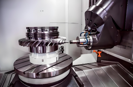
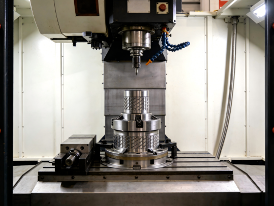
Machine type requirements. Three-axis CNC machines cost less to operate than five-axis equipment. If your geometry can be completed with 3-axis machining, costs stay lower. But parts requiring multi-angle access or complex contours may need 5-axis capability—increasing hourly rates and often requiring more skilled operators.
Material removal volume. CNC machining is subtractive—you're paying to cut away everything that isn't your final part. According to industry analysis, material wastage typically runs 30% to 70% of the original blank volume depending on part complexity. More material removal means more machining time, more tool wear, and higher costs.
Feature intricacy. Deep pockets, thin walls, tight internal corners, and complex contours all slow machining. Each feature may require multiple passes, specialized tooling, or careful feeds and speeds to achieve quality results. Simple prismatic shapes machine faster than organic curves.
Material machinability. Some materials cut easily; others fight back. Aluminum machining typically proceeds quickly with minimal tool wear—making it cost-effective for prototyping. Stainless steel and titanium require slower speeds, more frequent tool changes, and specialized cutting strategies. Similarly, cnc plastic machining varies widely: acetal and nylon cut cleanly, while filled materials or soft plastics demand more attention.
Tolerance requirements. As we discussed earlier, tighter tolerances increase machining time significantly. Precision work requires slower feeds, more measurement cycles, and potentially temperature-controlled inspection—all adding time and cost.
- Material costs – Raw material pricing plus waste from subtractive processing. Aluminum costs less than titanium; standard stock sizes reduce waste compared to custom blanks.
- Setup and programming – Fixed costs spread across your quantity. The dominant factor for single-part orders.
- Machining time – Hourly machine rates multiplied by cutting time. Driven by complexity, material, and machine type.
- Tolerance and inspection – Tighter specifications require more careful machining and extended quality verification.
- Surface finishing – Post-machining operations like anodizing, bead blasting, or polishing add labor and processing time.
- Expedite fees – Rush orders (1-3 days versus standard 7-10 days) command premium pricing due to schedule disruption.
Smart Strategies to Reduce Prototype Costs
Understanding cost drivers empowers you to optimize spending without compromising prototype value. Here's how experienced teams control their custom machined parts budgets:
Batch strategically. If you anticipate needing iterations, consider ordering 3-5 pieces initially rather than one. The per-part savings often offset total spending, and you'll have spares for destructive testing or parallel evaluation. Even if your design changes between batches, spreading setup costs across multiple units reduces overall development expense.
Simplify where possible. Before submitting for quotes, review your design for features that add machining time without functional benefit. Can that deep pocket be shallower? Can internal corners accept larger radii? Can decorative features wait until production? Each simplification reduces machining time and cost.
Choose materials wisely. If you're validating geometry rather than material performance, consider cost-effective alternatives. Aluminum prototypes that will eventually be titanium still validate fit and function—at a fraction of the price. Reserve expensive materials for final validation stages.
Specify tolerances selectively. Apply tight tolerances only where function demands them. A drawing with uniform tight tolerances costs significantly more than one with standard tolerances and a few critical dimensions called out precisely.
Accept standard finishes. As-machined surfaces (Ra 3.2 µm) add no cost. According to finishing cost analysis, smoother finishes of 1.6 µm, 0.8 µm, and 0.4 µm Ra add approximately 2.5%, 5%, and up to 15% to base pricing respectively. Specify enhanced finishes only where appearance or function requires them.
Plan lead times. Standard production schedules (7-10 days) cost less than expedited orders. Building realistic timelines into your development schedule avoids rush premiums that can double prototype costs.
The transition from prototype to production brings its own economic shift. Those NRE costs that dominated your prototype pricing become negligible when spread across thousands of units. Understanding this transition helps you plan budgets realistically—and appreciate that expensive prototypes often indicate a well-validated path to cost-effective production.
Cost optimization matters, but it's only valuable if your prototypes actually meet the standards your application demands. For automotive, aerospace, and medical projects, that means understanding which industry certifications should factor into your provider selection.
Industry Certifications That Matter for Prototypes
You might wonder: why do certifications matter for prototypes? After all, you're building a few test parts—not launching a production run for a major automaker or medical device company.
Here's the reality that experienced product teams understand: your prototype decisions shape your production path. If you validate a design using a shop that can't meet your industry's quality standards, you'll face uncomfortable choices later—either requalify with a certified supplier (adding time and cost) or discover manufacturing variations that invalidate your prototype testing entirely.
For automotive, aerospace, and medical applications, certifications aren't bureaucratic checkboxes. They're your assurance that prototypes accurately represent what production parts will deliver. Let's decode what each major certification actually means for your prototype work.
Automotive Prototypes That Meet Supply Chain Standards
The automotive industry demands consistent, defect-free parts—and that expectation extends to prototypes that inform production decisions. According to industry certification specialists, IATF 16949 is the global standard for automotive quality management, combining ISO 9001 principles with sector-specific requirements for continuous improvement, defect prevention, and stringent supplier oversight.
What does IATF 16949 certification mean in practice? Facilities holding this certification have demonstrated:
- Robust process control – documented procedures that ensure repeatable results across production runs
- Defect prevention systems – proactive quality measures rather than reactive inspection
- Full traceability – ability to track materials, processes, and measurements for every part produced
- Continuous improvement culture – systematic methods for identifying and eliminating variation sources
For prototype work, this matters because your test results need to reflect genuine production capability. A prototype machined without process controls might perform beautifully—but if production parts show more variation, your validation testing becomes meaningless.
Statistical Process Control (SPC) plays a crucial role here. Even in prototype quantities, IATF 16949-certified facilities apply SPC principles to monitor dimensional consistency and identify trends before they become problems. This discipline ensures your five prototype chassis brackets exhibit the same quality characteristics that thousands of production units will deliver.
If your automotive supply chain requires IATF 16949 compliance, working with certified providers from the prototype stage eliminates transition risk. You validate designs using the same quality systems that will govern production—giving OEM customers confidence that your prototypes accurately predict production performance. Providers like Shaoyi Metal Technology offer IATF 16949-certified precision machining service with SPC protocols, delivering high-tolerance components for chassis assemblies and custom metal bushings with lead times as fast as one working day.
Aerospace-Grade Prototyping Requirements
Aerospace cnc machining operates under some of the most rigorous compliance standards in manufacturing. When parts fly at 30,000 feet or travel to orbit, there's zero tolerance for quality shortcuts—and that philosophy applies equally to prototypes that validate flight-critical designs.
AS9100D builds upon ISO 9001 foundations while introducing requirements specific to aerospace machining demands. According to aerospace CNC specialists, certified facilities demonstrate quality compliance through ISO 9001:2015, AS9100, and ITAR registration—providing the documentation and process controls that aerospace programs require.
Key AS9100D requirements that affect cnc machining aerospace work include:
- Risk management integration – systematic identification and mitigation of quality risks throughout manufacturing
- Configuration management – rigorous control of design changes and their implementation
- Product integrity controls – counterfeit part prevention and material authenticity verification
- Special process accreditation – NADCAP certification for heat treating, chemical processing, and non-destructive testing
For aerospace prototypes, traceability becomes especially critical. You need documented evidence of material certifications, processing parameters, and inspection results. When your prototype undergoes qualification testing, auditors will expect complete records—from raw material mill certificates through final dimensional reports.
The precision machining service requirements for aerospace work also extend to equipment capabilities. Complex aerospace components often require 5-axis machining to access features from multiple angles, and certified facilities maintain the equipment calibration and process validation that aerospace programs demand.
Medical Device Prototypes and Regulatory Pathways
Medical device machining carries unique responsibilities. According to ISO 13485-certified prototyping specialists, medical device rapid CNC prototyping under this certification enforces strict quality requirements essential for patient safety.
ISO 13485:2016 provides a detailed framework specifically designed for organizations involved in the design, production, installation, and servicing of medical devices. Unlike general quality standards, it addresses the unique challenges of medical device machining where product safety directly influences patient outcomes.
The 2016 revision introduced several changes that directly impact medical prototyping:
- Expanded risk management – risk-based thinking applied to every quality management process, not just final products
- Software validation requirements – covering software used in quality systems, critical for CNC equipment programming
- Strengthened supplier controls – more robust procedures ensuring purchased materials and components meet specifications
- Enhanced documentation – comprehensive records throughout the product lifecycle, including material selection and machining parameters
For medical device prototypes, FDA alignment matters enormously. ISO 13485:2016 harmonizes with FDA 21 CFR Part 820 requirements, simplifying regulatory compliance for manufacturers targeting the U.S. market. Prototypes machined under ISO 13485 protocols generate documentation that supports regulatory submissions—rather than creating gaps that require additional testing.
Medical device machining also demands exceptional surface finish quality. According to prototyping specialists, surface roughness affects not just aesthetics but functionality, durability, and patient safety. Properly controlled surface finishes enhance corrosion resistance, reduce bacterial growth potential, and ensure biocompatibility—all critical factors verified during prototype testing.
| Certification | Industry Focus | Key Requirements | When Prototypes Need It |
|---|---|---|---|
| IATF 16949 | Automotive | Continuous improvement, defect prevention, SPC, supplier oversight, full traceability | Prototypes for OEM supply chains, production validation testing, supplier qualification |
| AS9100D | Aerospace | Risk management, configuration control, product integrity, NADCAP special processes | Flight-critical components, qualification testing, programs requiring full traceability |
| ISO 13485:2016 | Medical Devices | Risk-based approach, design controls, software validation, FDA 21 CFR Part 820 alignment | Prototypes supporting regulatory submissions, biocompatibility testing, clinical evaluation |
| ISO 9001:2015 | General Manufacturing | Quality management fundamentals, process approach, customer focus, continual improvement | Baseline quality assurance for non-regulated applications, commercial prototyping |
| NADCAP | Aerospace/Defense Special Processes | Heat treating, chemical processing, NDT, coating accreditation | Prototypes requiring certified special processes (anodizing, heat treatment, NDT inspection) |
The bottom line? Certifications signal capability. A shop holding AS9100D or ISO 13485 has invested in systems, training, and equipment that ensure consistent quality—whether producing one prototype or one thousand production parts. For applications where your prototype testing must accurately predict production performance, working with certified providers isn't optional. It's the foundation of reliable product development.
Certifications tell you what a shop has proven they can do. But how do you evaluate whether a specific provider is right for your prototype project? That requires asking the right questions—which we'll explore next.
Evaluating Prototype CNC Service Providers
You've nailed down your design, selected appropriate materials, and understand what certifications your project demands. Now comes a decision that can make or break your prototype timeline: choosing the right machining partner.
Searching for a "cnc machine shop near me" or "machinist near me" might seem like a logical starting point—but proximity alone doesn't guarantee capability. The best prototype CNC provider for your project depends on a careful evaluation of technical skills, quality systems, communication practices, and the ability to grow with your needs.
Let's walk through how to separate genuinely capable providers from those who simply have the right marketing.
Questions That Reveal True Capabilities
Anyone can claim expertise. The right questions cut through marketing language and reveal what a shop can actually deliver. According to precision machining specialists, evaluating a CNC shop's experience should start with direct inquiries about their track record and qualifications.
Start with these essential questions:
- How many years have you been providing CNC machining services? Longevity suggests stability and refined processes. Shops that have operated successfully for a decade or more have typically weathered challenges and developed reliable workflows.
- Can you provide examples of projects similar to mine? Past performance predicts future results. Request case studies or references from projects matching your complexity, material, and tolerance requirements.
- What qualifications do your machinists and programmers hold? Technical expertise matters enormously. Skilled operators can troubleshoot issues that less experienced teams might not even recognize.
- Do you outsource any operations? Many shops outsource finishing, heat treating, or specialized processes. This isn't necessarily problematic—but you need to understand how they manage external vendors to prevent delays and maintain quality control.
- What's your typical turnaround for projects like mine? Ask for realistic timelines based on current workload, not best-case scenarios. According to industry vetting guidelines, clarifying lead times upfront prevents unpleasant surprises.
Pay attention to how providers respond. Shops that ask clarifying questions about your requirements demonstrate thoroughness. Those who quote immediately without understanding your project may be estimating blindly—setting you up for requotes or quality issues later.
Equipment and Expertise to Verify
The machinery a shop operates directly determines what they can produce. Understanding equipment capabilities helps you match providers to your technical requirements.
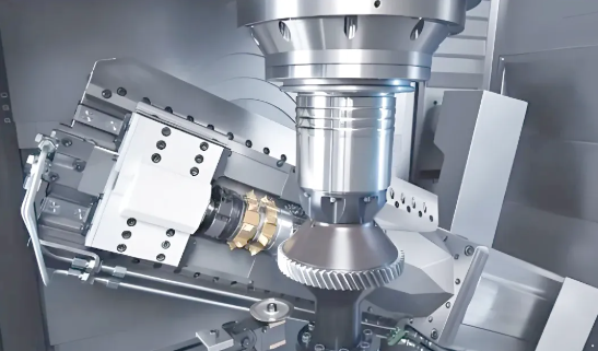
Multi-axis capabilities matter. Three-axis CNC machines handle straightforward geometries efficiently. But if your prototype features undercuts, complex contours, or features requiring access from multiple angles, you'll need a shop offering 5 axis cnc machining services. According to manufacturing experts, advanced multi-axis capabilities allow creation of complex shapes with fewer setups—reducing error risk and improving turnaround times.
Beyond axis count, verify:
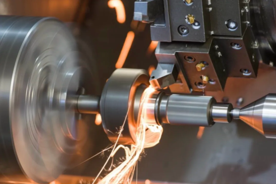
- Machine types available – Does the shop operate both milling and turning equipment? Swiss-type lathes for small, intricate components? The right equipment mix for your part geometry prevents outsourcing delays.
- Work envelope capacity – Can their machines accommodate your part dimensions? Oversized or unusually shaped parts may require specialized equipment.
- Inspection equipment – Coordinate Measuring Machines (CMMs) provide precise verification of critical dimensions. Shops relying solely on manual inspection may struggle with tight-tolerance work.
- Material experience – Some precision machining companies specialize in specific material categories. A shop expert in aluminum may struggle with exotic alloys or engineering plastics. Verify experience with your specific materials before committing.
Request facility tours when possible—or ask for photos and equipment lists. Reputable custom cnc machining services providers are typically proud to showcase their capabilities.
Finding Partners Who Scale With Your Project
Here's a consideration many prototype buyers overlook: what happens after validation succeeds? If your prototype proves out and you're ready for production, switching providers means requalifying processes, potentially discovering variations between prototype and production parts, and losing the institutional knowledge your prototype partner developed.
The most efficient development path uses a single provider from prototyping through production. According to manufacturing partnership guidance, finding partners who can support your project from initial concept through full-scale production offers continuity and efficiency that fragmented supply chains cannot match.
Evaluate scalability by asking:
- Can you handle both rapid prototyping and high-volume production runs?
- What's your capacity for scaling from 5 units to 500 or 5,000?
- Do you offer design feedback to improve manufacturability before production commitment?
- Will you maintain our tooling and programs for future orders?
Geographic considerations also factor into scalability decisions. According to sourcing analysis, local providers excel when you need rapid turnaround, frequent design iterations, or hands-on quality oversight. Direct communication, shorter shipping times, and the ability to visit facilities provide advantages that offset potentially higher per-part costs.
Overseas providers—particularly in regions with mature manufacturing ecosystems—often deliver cost advantages for standardized, high-volume production. However, longer shipping times, customs complexity, and communication challenges make them less suitable for fast-iteration prototyping where machining services near me offers compelling advantages.
The practical approach? Use local providers for prototype iterations where speed and communication matter most. Evaluate overseas options when transitioning to production volumes where cost efficiency becomes dominant—but only after validating that quality systems meet your requirements.
- Verify certifications match your industry requirements – ISO 9001 minimum; IATF 16949, AS9100D, or ISO 13485 for regulated applications.
- Confirm equipment capabilities align with your geometry – 3-axis versus 5-axis, milling versus turning, work envelope dimensions.
- Validate material expertise – Request examples of similar materials successfully machined.
- Assess communication responsiveness – How quickly and thoroughly do they respond to inquiries? This predicts project communication quality.
- Request realistic lead time commitments – Based on current capacity, not theoretical best-case.
- Evaluate scalability potential – Can they transition from prototypes to production volumes?
- Check references and reputation – Contact previous customers; review testimonials and case studies.
- Understand their quality control processes – CMM inspection, SPC monitoring, first-article procedures.
- Clarify communication protocols – Dedicated point of contact, update frequency, issue escalation procedures.
- Review geographic fit – Local for iteration speed; consider overseas for production cost optimization.
Red flags to watch for? Providers who quote without asking questions, promise unrealistic timelines, lack relevant certifications, or cannot provide references from similar projects. The cheapest quote often becomes the most expensive mistake when delays, quality issues, or production transition problems emerge.
Selecting the right prototype CNC provider is ultimately about finding a manufacturing partner—not just a vendor. The relationship you build during prototyping sets the foundation for everything that follows, from design iteration through production launch and beyond.
Maximizing Value From Your Prototype Investment
You've navigated material selection, tolerance specifications, file preparation, and provider evaluation. Now comes the strategic question that separates efficient product development from expensive trial-and-error: how do you extract maximum value from every prototype iteration?
The answer lies in approaching cnc prototype machining as a learning system rather than a quest for immediate perfection. According to product development research, prototyping isn't just a phase—it's a strategic tool that offers early insights into consumer preferences and market dynamics. Companies that embrace this mindset reduce risks, enhance market fit, and accelerate successful launches.
Let's explore how to plan your prototype investments strategically, transition smoothly to production, and build partnerships that serve you from first concept through mass manufacturing.
Planning for Iteration Not Perfection
Here's a mindset shift that saves both time and money: your first prototype shouldn't try to be perfect. It should try to answer specific questions.
Consider Xiaomi's approach when entering the competitive smartphone market. According to case study analysis, Xiaomi developed the Mi1 smartphone by gathering real-time feedback from millions of users through iterative prototyping. This approach propelled them from newcomer to global leader within just a few years. The lesson? Rapid learning beats slow perfection.
Structure each prototype around testable hypotheses:
- Iteration 1 – Does the basic geometry work? Do components fit together as designed?
- Iteration 2 – How does the design perform under realistic stress conditions?
- Iteration 3 – Can we achieve required tolerances with production-equivalent materials?
- Iteration 4 – Does the assembly process work at speed? Are there ergonomic issues?
Each cycle answers specific questions rather than trying to validate everything simultaneously. This focused approach means you can use cost-effective materials early—saving premium production-equivalent testing for later iterations when geometry is locked.
The economic logic is compelling. According to manufacturing specialists, simple low-cost prototypes may cost between $100 and $1,000, while production-ready high-fidelity prototypes can exceed $10,000. Spending high-fidelity money on early iterations where designs will change wastes resources that could fund additional learning cycles.
The fastest path to a successful product isn't building one perfect prototype—it's building multiple focused prototypes that systematically eliminate uncertainty. Each iteration reduces risk, and reduced risk translates directly to lower overall development costs and faster market entry.
From Validated Prototype to Production Confidence
The transition from prototype machining services to production represents a critical handoff. Everything you learned during prototyping should inform production decisions—but only if you've captured that knowledge systematically.
According to prototype-to-production specialists, successful transitions require careful planning to maintain tight tolerances, repeatable quality, and full traceability. The iterative approach during prototyping—refining tolerances, geometries, and surface finishes as needed—generates insights that directly apply to production planning.
Key transition considerations include:
- Process documentation – Capture machining parameters, tooling selections, and fixture designs that produced successful prototypes. This institutional knowledge prevents rediscovery during production setup.
- Tolerance validation – Confirm that tolerances achieved during cnc machining prototyping are sustainable at production volumes. Some tight specifications may require process adjustments for consistency across thousands of parts.
- Material qualification – If prototypes used alternative materials for cost efficiency, final validation using production-equivalent materials becomes essential before committing to tooling.
- Assembly verification – Test assembly procedures with prototype precision machining parts to identify bottlenecks before production volumes expose them.
The value of cnc turning services and milling operations during prototyping extends beyond the parts themselves. You're simultaneously validating manufacturability—confirming that your design can be produced consistently, economically, and at the quality levels your application demands.
Low-volume production runs bridge the gap between prototyping and full-scale manufacturing. According to manufacturing guidance, this stage helps catch design, manufacturing, or quality issues while validating processes, identifying bottlenecks, and assessing supplier capabilities. Consider ordering 25-100 units as a production pilot before committing to thousands.
Building Long-Term Manufacturing Partnerships
The most valuable outcome of your prototyping investment isn't just validated parts—it's a validated manufacturing partnership.
When you work with a cnc prototyping service provider through multiple iterations, they develop deep understanding of your design intent, quality requirements, and application demands. This knowledge becomes invaluable during production transition. A provider who machined your prototypes understands nuances that would take a new supplier months to learn.
Look for partners offering capabilities that span the complete development cycle:
- Rapid turnaround for iterations – Some certified facilities deliver precision machining parts with lead times as fast as one working day for urgent design cycles. This speed enables more learning cycles within compressed development schedules.
- Quality consistency from prototype to production – Providers with robust SPC protocols maintain dimensional consistency whether producing five units or five thousand. This consistency ensures your prototype validation accurately predicts production performance.
- Scalable capacity – The ability to grow from small-batch prototyping through high-volume production without changing suppliers eliminates transition risks and qualification delays.
For automotive applications, this partnership value becomes especially clear. Facilities like Shaoyi Metal Technology combine IATF 16949 certification with rapid prototyping capabilities—delivering complex chassis assemblies and custom metal bushings with the quality documentation automotive supply chains require. Working with such providers from the prototype stage means your validation testing reflects genuine production capability.
The economics favor long-term partnerships as well. According to supply chain analysis, reliable partners offer access to established supply chain networks ensuring steady material supply, while their design optimization expertise helps refine prototypes for cost-effective and scalable production.
As you evaluate potential partners, consider their willingness to provide design feedback. The best cnc prototyping service providers don't just execute your files—they identify manufacturability improvements that reduce production costs and improve quality. This collaborative approach transforms a transactional vendor relationship into a strategic partnership.
Strategic prototyping isn't about minimizing prototype spending. It's about maximizing prototype learning. Every iteration that answers critical questions moves you closer to production confidence. Every partnership that maintains quality consistency from first prototype through mass production reduces your total development risk.
The companies that launch successful products fastest aren't those with unlimited budgets—they're those who plan their prototype investments strategically, capture learnings systematically, and build manufacturing relationships that support them from concept through scale. Your prototype CNC services investment, approached with this strategic mindset, becomes the foundation for everything that follows.
Frequently Asked Questions About Prototype CNC Services
1. What is the difference between prototype CNC machining and production machining?
Prototype CNC machining focuses on producing small quantities of parts quickly for design validation, testing, and iteration before full-scale manufacturing. Production machining prioritizes efficiency and high-volume output of identical parts. Prototyping emphasizes speed, flexibility, and learning, while production optimizes for cost-per-unit and consistency across thousands of parts. Setup costs dominate prototype pricing since NRE expenses spread across fewer units.
2. How fast can I get CNC machined prototypes?
Most prototype CNC services deliver finished parts within 2-7 working days for standard geometries and materials. Some certified facilities offer expedited turnaround as fast as one working day for urgent iterations. Lead times depend on part complexity, material availability, tolerance requirements, and current shop capacity. Rush orders typically command premium pricing due to schedule disruption.
3. What file format should I use for CNC prototype quotes?
STEP files (.stp, .step) are the gold standard for CNC prototyping quotes. They preserve solid geometry, maintain dimensional accuracy, and work universally across CAM software. IGES and Parasolid formats also work well. Avoid mesh-based formats like STL, which break smooth curves into triangles and degrade precision. Include native CAD files when possible, but always provide a STEP export for compatibility.
4. Why do single CNC prototypes cost more per part than larger quantities?
Single prototypes absorb the entire fixed cost of programming, setup, tooling preparation, and first-article inspection. These Non-Recurring Engineering (NRE) expenses remain constant regardless of quantity. When ordering 10 units instead of one, per-part costs can drop by 70% because setup costs spread across more pieces. The actual machining cost per part changes minimally—it's the NRE amortization that drives the economics.
5. What certifications matter for prototype CNC services?
ISO 9001 provides baseline quality assurance for general prototyping. Automotive applications require IATF 16949 certification for supply chain compliance. Aerospace prototypes demand AS9100D certification with full traceability and risk management. Medical device prototypes need ISO 13485:2016 for FDA alignment. Working with certified providers from the prototype stage ensures validation testing reflects genuine production capability.