 Small batches, high standards. Our rapid prototyping service makes validation faster and easier —

Preventing Wrinkling in Metal Stamping: The Engineering Guide
TL;DR
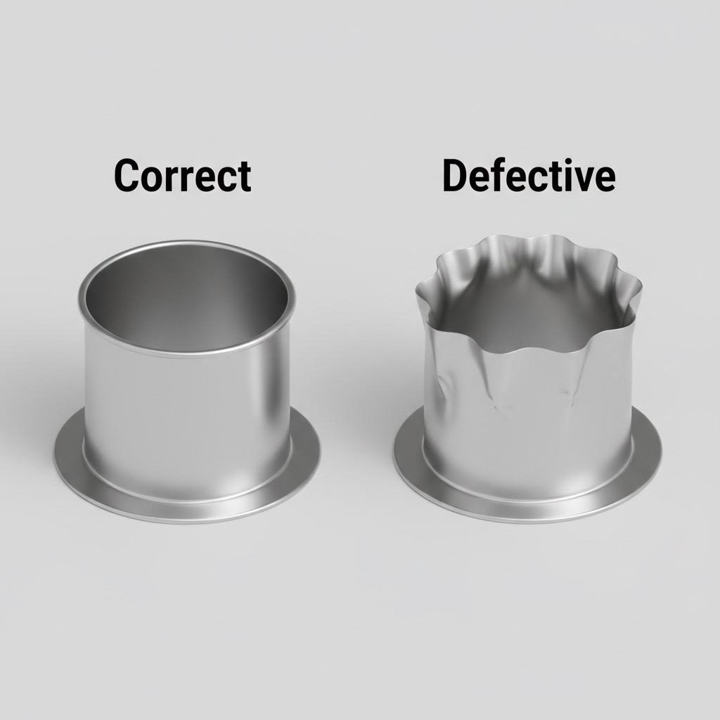
Wrinkling in metal stamping is primarily caused by compressive hoop stresses in the flange area as the blank diameter is reduced to the cup diameter. When the material cannot compress into itself, it buckles.
The most effective prevention method is applying the correct Blank Holder Force (BHF) to restrict material flow without causing tearing. For steel, a pressure of approximately 2.5 N/mm² is the standard baseline. Secondary controls include using draw beads to mechanically restrain flow in complex areas and ensuring die radii are optimized (not too large) to maintain tension. Operators should prioritize balancing flow resistance against the material's Limiting Draw Ratio (LDR).
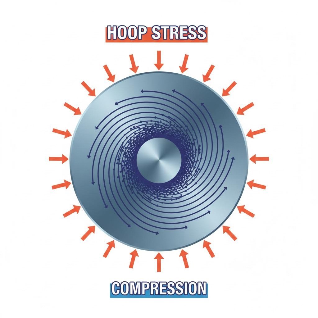
The Physics of Wrinkling: Why Metal Buckles
To effectively prevent wrinkling, engineers must first understand the mechanism of compressive instability. During deep drawing, a flat blank is transformed into a three-dimensional shape. As the material flows from the outer edge of the blank toward the die cavity, the circumference decreases. This reduction forces the material to compress tangentially (hoop stress). If this compressive stress exceeds the material's critical buckling stress, the metal waves or folds, creating wrinkles.
This phenomenon is governed by the Limiting Draw Ratio (LDR)—the relationship between the blank diameter and the punch diameter. When the blank is too large relative to the punch, the amount of material "gathering" in the flange becomes unmanageable, leading to severe thickening. If the gap between the die face and the blank holder is not strictly controlled to accommodate this thickening (typically allowing only 10-20% clearance above nominal thickness), the material will buckle into the empty space.
Wrinkling manifests in two primary forms: Flange Wrinkling (First-Order), which occurs in the area under the binder, and Wall Wrinkling (Second-Order), which happens in the unsupported region between the die radius and the punch radius. Identifying where the wrinkle initiates is the first step in diagnostics: flange wrinkles suggest insufficient binder pressure, while wall wrinkles often point to excessive die radii or poor material fit-up.
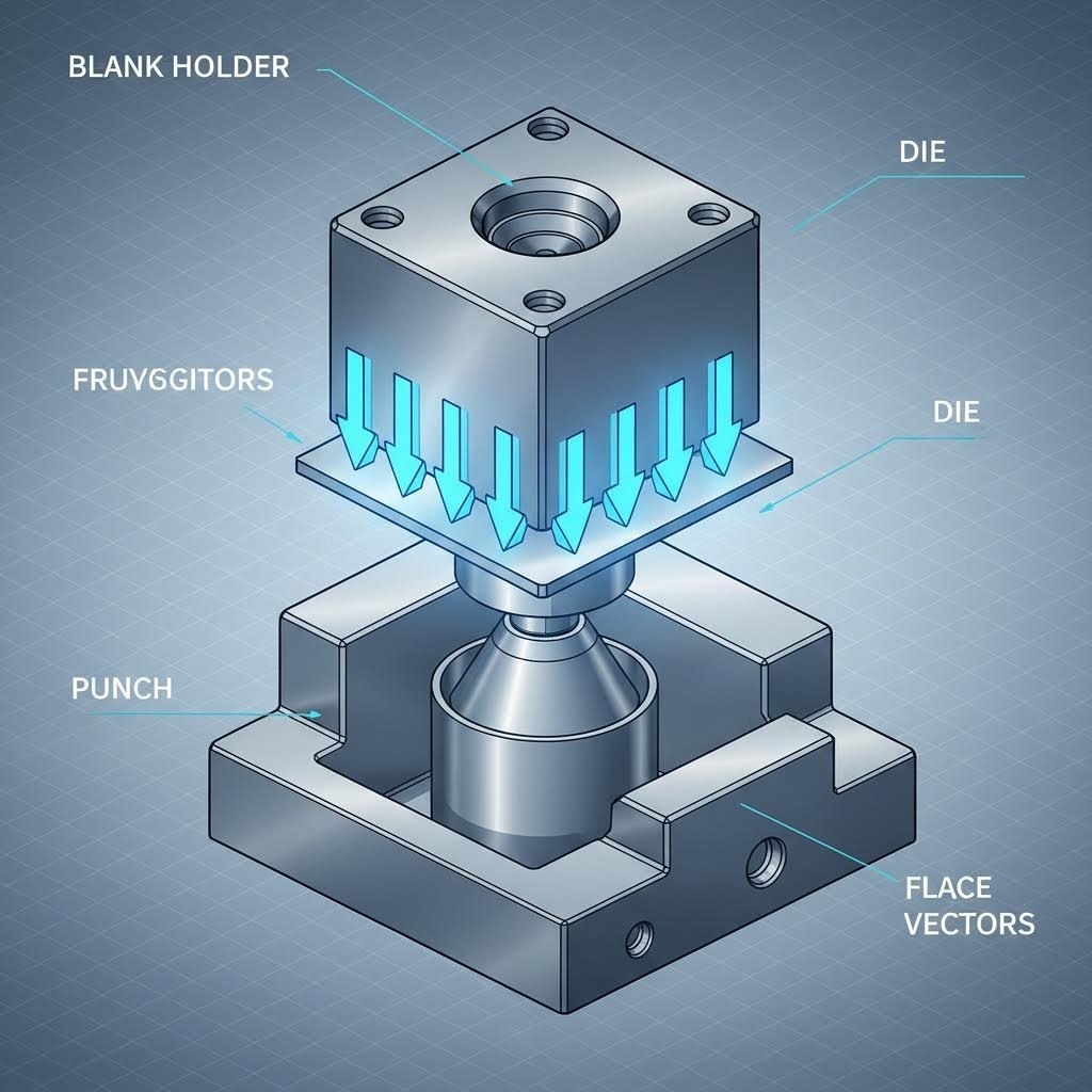
Primary Solution: Optimizing Blank Holder Force (BHF)
The Blank Holder (or binder) is the primary control variable for preventing wrinkles. Its function is to apply sufficient pressure to the flange to suppress buckling while allowing the material to flow into the die. If the pressure is too low, wrinkles form; if it is too high, the material tears (fractures) because it cannot flow.
According to industry standards, the required specific pressure varies significantly by material type. A practical rule of thumb for initial setup is:
- Steel: ~2.5 N/mm²
- Copper Alloys: 2.0 – 2.4 N/mm²
- Aluminum Alloys: 1.2 – 1.5 N/mm²
Engineers should calculate the required force based on the projected area of the flange under the binder. It is advisable to add a safety factor of roughly 30% to this calculation during the design phase, as it is easier to reduce pressure on the press than to generate more force than the design allows.
For complex parts, uniform pressure is often insufficient. Advanced setups utilize variable pressure systems (hydraulic or nitrogen cushions) that can adjust force throughout the stroke—applying high pressure initially to set the flange and reducing it as the part deepens to prevent tearing. Using standoffs or equalizer blocks (stop blocks) is critical to maintain a precise gap that is slightly thicker than the material, ensuring the binder doesn't simply crush the sheet but rather restrains it.
Tooling Design Controls: Draw Beads and Radii
When pressure alone cannot control the material flow—often the case with non-symmetrical automotive parts—draw beads are the required engineering solution. Draw beads are raised ribs on the binder that force the material to bend and unbend before entering the die cavity. This mechanical action creates a restraining force independent of friction, allowing for precise local flow control.
The geometry of the die radius is equally critical. A radius that is too small restricts flow and causes splitting, but a radius that is too large reduces the contact area and effective tension on the flange, encouraging material to flow too freely and wrinkle. The die radius must be perfectly polished and geometrically accurate to maintain the "sweet spot" of tension.
Furthermore, the rigidity of the tool itself matters. If the die shoe is not thick enough, it may flex under tonnage, creating uneven pressure distribution. Guide pins must be robust enough to prevent any lateral movement of the top and bottom tooling, which would cause inconsistent gaps and localized wrinkling.
Process Variables: Lubrication and Material Selection
Friction is a double-edged sword in deep drawing. While lubrication is essential to prevent galling and splitting, excessive lubricity (too much slip) can actually worsen wrinkling if the BHF is not increased to compensate. The material flows so easily that the binder cannot generate enough friction to hold back the buckling forces. Ensure lubricant is applied consistently and nozzles are fixed in position.
Material properties also dictate the process window. For stainless steel applications, replacing standard 304 with 304L can significantly improve formability. 304L has a lower yield strength (approx. 35 KSI vs. 42 KSI for 304), meaning it resists flow less and work-hardens more slowly, reducing the force required to keep it flat. Always verify that the raw material is specified as "Deep Draw Quality" (DDQ) to minimize anisotropy.
Even with perfect design, the physical capability of your manufacturing partner is a limiting factor. For high-volume automotive components like control arms or subframes, precision is non-negotiable. Manufacturers like Shaoyi Metal Technology leverage presses with capacities up to 600 tons and IATF 16949 certification to bridge the gap from rapid prototyping to mass production. Partnering with a specialist ensures that the theoretical BHF calculations are matched by actual equipment capability, preventing defects before they reach the assembly line.
Troubleshooting Checklist: A Step-by-Step Protocol
When wrinkles appear on the production line, follow this systematic diagnostic workflow to isolate the root cause:
- Inspect the Press: Check for worn gibs or ram non-parallelism. If the ram is not coming down square, pressure distribution will be uneven.
- Verify Material Specs: Is the material thickness consistent? Measure the edge of the coil; variations of even 0.003 inches can affect the binder gap.
- Check Standoffs: Are the stop blocks setting the correct gap? If they are worn or loose, the binder may be "bottoming out" before applying force to the sheet.
- Adjust BHF Incrementally: Increase binder pressure in small steps. If wrinkles persist but splitting starts, you have narrowed the process window too much—look to draw beads or lubrication changes.
- Audit Lubrication: Check if the lube mixture is too rich or applied too heavily in the flange area.
- Examine Tooling Surface: Look for galling on the draw beads or radii that might be creating uneven drag.
Mastering the Flow
Preventing wrinkling is not about eliminating force, but about managing it with precision. It requires a holistic approach that balances the physics of hoop stress against the engineering controls of blank holder force, tool geometry, and material selection. By treating the stamping process as a system of interacting variables rather than isolated steps, manufacturers can achieve consistent, defect-free deep drawn parts.
Success lies in the details: the precise calculation of N/mm² pressure, the strategic placement of draw beads, and the discipline to maintain press and tool conditions. With these controls in place, even the most complex geometries can be formed reliably.
Frequently Asked Questions
1. How do I calculate the correct blank holder force?
The baseline calculation involves multiplying the area of the flange (under the binder) by the specific pressure required for the material. For mild steel, use approximately 2.5 N/mm² (MPa). Always add a safety margin (e.g., +30%) to your press capacity requirements to allow for adjustments during tryout.
2. Can too much lubricant cause wrinkling?
Yes. Lubricant reduces friction, which is one of the forces that helps restrain material flow. If the friction drops significantly without a corresponding increase in Blank Holder Force, the material may flow too freely into the die cavity, leading to buckling and wrinkles.
3. What is the difference between wrinkling and tearing?
Wrinkling and tearing are opposite failure modes. Wrinkling is caused by excessive compression and insufficient flow restriction (loose material). Tearing (splitting) is caused by excessive tension and too much flow restriction (tight material). The goal of the stamper is to find the "process window" between these two defects.