 Small batches, high standards. Our rapid prototyping service makes validation faster and easier —

Precision Sheet Metal Forming: From Costly Defects To Flawless Parts
Defining Precision Sheet Metal Forming and Its Tolerance Standards
When does sheet metal forming cross the line from "good enough" into true precision territory? If you've ever dealt with parts that almost fit or assemblies requiring constant adjustment, you already understand why this distinction matters. Precision sheet metal forming isn't just a marketing term—it's a measurable standard that separates engineering-grade manufacturing from general fabrication work.
At its core, precision sheet metal forming refers to the controlled deformation of thin metal stock (typically 0.1mm to 3mm thick) into complex geometries while maintaining exceptionally tight dimensional accuracy. Unlike standard fabrication, which accepts tolerances of ±1.6mm to ±3.2mm, precision work demands something far more exacting.
What Separates Precision from Standard Forming
The difference comes down to three critical factors: achievable tolerances, process control, and verification methods.
Standard sheet metal fabrication handles everyday manufacturing needs—think HVAC ductwork, basic enclosures, or structural brackets. These applications tolerate dimensional variations of ±0.8mm to ±1.6mm without functional consequences. The equipment, training, and quality systems supporting this work are optimized for speed and cost-efficiency rather than extreme accuracy.
Precision sheet metal forming operates in a different realm entirely. According to industry specifications, this approach maintains dimensional tolerances of ±0.1mm to ±0.05mm or tighter. Reaching pinnacle precision sheet metal standards requires advanced CNC equipment, sophisticated tooling, comprehensive material knowledge, and rigorous statistical process control.
Consider what this means practically: in precision work, a bend angle deviation of just 0.5° could cause rejection, while standard fabrication might accept variations up to 2° without concern.
Industry Tolerance Standards Explained
So what officially qualifies work as precision-grade? International standards provide the definitive benchmarks.
Precision sheet metal forming is defined by dimensional tolerances of ±0.1mm (±0.004") or tighter, as established by ISO 2768 fine tolerance grades and ASME Y14.5 geometric dimensioning standards.
The most commonly referenced standards include:
- ISO 2768-1 and ISO 2768-2: General tolerances for linear and geometric features, with fine (f) and very fine grades defining precision thresholds
- ASME Y14.5: The American standard for geometric dimensioning and tolerancing (GD&T), critical for complex positional and form requirements
- ISO 1101: Geometric product specifications governing flatness, perpendicularity, and profile tolerances
Under ISO 2768-m (medium grade), a 120-400mm dimension allows ±0.5mm variation. But precision applications demand tighter control—often achieving ±0.13mm to ±0.25mm across complex geometries through advanced equipment and process optimization.
For engineers and technical buyers evaluating forming sheet metal capabilities, these tolerance benchmarks provide objective criteria. When a supplier claims "precision" capability, ask for documented tolerance achievements on similar geometries. Pinnacle precision sheet metal work should demonstrate consistent results verified through coordinate measuring machines (CMM), optical comparators, or laser measurement systems—not just visual inspection.
Understanding these standards protects your projects from costly surprises. A component specified at ±0.1mm tolerance simply cannot be reliably produced on equipment designed for ±1mm work, regardless of operator skill. The distinction between precision and standard forming begins with equipment capability and extends through every aspect of the manufacturing process.
The Science Behind Precision Metal Forming Processes
Ever wonder why two seemingly identical forming operations produce drastically different results? The answer lies in the physics happening at the molecular level. Understanding the steel forming process fundamentals gives you the knowledge to predict outcomes, troubleshoot problems, and consistently achieve the tight tolerances precision work demands.
When force is applied to sheet metal, you're not simply bending material—you're reorganizing its crystalline structure. This transformation follows predictable rules, and mastering these principles separates precision fabricators from those constantly fighting dimensional issues.
How Metal Behaves Under Forming Stress
Imagine stretching a rubber band slightly, then releasing it. It snaps back to its original shape—that's elastic deformation. Now stretch it far enough that it stays elongated after you let go. That permanent change? That's plastic deformation, and it's the foundation of every sheet metal forming process.
According to manufacturing fundamentals research, metals transition from elastic to plastic deformation at a specific stress level called the yield point. Below this threshold, your material springs back completely. Above it, permanent shape change occurs. For precision work, understanding exactly where this transition happens for your specific material is essential.
Here's where things get interesting for precision applications:
- Strain hardening: As metal deforms plastically, it actually becomes stronger and harder. This work hardening effect means the force required to continue deformation increases progressively—a critical factor when calculating press tonnage and predicting springback.
- Flow stress: This represents the instantaneous force needed to continue yielding at any point during forming. For processes like deep drawing, understanding flow stress variations across the workpiece prevents thinning failures and dimensional drift.
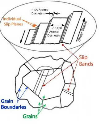
- Grain structure: Sheet metal consists of crystalline grains oriented in specific patterns from prior processing. These grains rotate and elongate during forming, creating directional strength properties that affect both formability and final part behavior.
The practical implication? A part formed along the material's rolling direction will behave differently than one formed across it—sometimes by enough to push your tolerances out of specification.
Critical Process Variables for Accuracy
Achieving consistent precision in metal forming techniques requires controlling multiple interdependent variables. Change one parameter, and you'll likely need to adjust others to maintain dimensional accuracy.
Temperature deserves special attention. Cold forming (room temperature) produces stronger, harder parts with excellent surface finish and tight tolerances—but requires higher forces and limits how much deformation you can achieve before material failure. Hot forming dramatically reduces required forces and enables massive shape changes, but sacrifices dimensional accuracy and surface quality.
The sheet metal forming process also depends heavily on strain rate—essentially, how fast you're deforming the material. Higher forming speeds affect flow stress differently depending on the metal and temperature. For precision work, this means your press speed settings directly influence dimensional outcomes.
| Process Parameter | Impact on Dimensional Accuracy | Precision Control Strategy |
|---|---|---|
| Forming Force | Insufficient force causes incomplete forming and springback; excessive force creates thinning and potential cracking | Calculate required tonnage based on material yield strength, part geometry, and desired deformation; use force monitoring systems |
| Forming Speed | Faster speeds increase strain rate sensitivity effects; slower speeds improve material flow uniformity but reduce productivity | Match speed to material characteristics; use controlled velocity profiles for complex geometries |
| Temperature | Higher temperatures reduce springback but decrease dimensional precision; cold forming maximizes accuracy but limits formability | Select temperature range based on tolerance requirements; maintain consistent temperature throughout production runs |
| Friction/Lubrication | High friction restricts material flow and causes uneven deformation; too little friction can cause wrinkling in draw operations | Apply appropriate lubricants consistently; specify friction coefficients in forming simulations |
| Tooling Clearance | Improper clearances cause material thickening, locking, or excessive thinning—all destroying dimensional control | Set clearances based on material thickness plus 10-30% depending on material type and draw depth |
One often-overlooked factor is the mechanical properties of your incoming material. As simulation experts emphasize, no forming analysis is accurate without confirmed stress-strain data for your specific material batch. Heat-to-heat variations in material properties can shift your dimensional results enough to exceed precision tolerances—even when all other parameters remain constant.
The interplay between these variables explains why steel forming often requires iterative optimization. A change in material supplier might necessitate adjusted forming speeds. Switching to a different lubricant could require modified tooling clearances. For precision work, documenting these relationships through controlled experiments builds the process knowledge that ensures repeatable results.
With these fundamentals established, the next critical decision involves selecting the right forming technique for your specific application requirements and precision targets.
Comparing Precision Forming Techniques for Different Applications
Choosing the right precision sheet metal fabrication technique feels overwhelming when you're staring at six viable options—each claiming to deliver superior results. Here's the reality: no single method wins across all applications. The technique that produces flawless aerospace brackets might be completely wrong for your automotive panel production. Understanding where each method excels (and where it struggles) transforms this decision from guesswork into strategic advantage.
Let's break down the major sheet forming techniques with the substantive comparison you actually need—covering not just what each method does, but when it delivers optimal precision and when you should look elsewhere.
Technique Selection Based on Part Geometry
Your part's geometry is the first filter for narrowing technique options. Complex three-dimensional shapes, shallow draws, long linear profiles, and intricate contours each point toward different forming and metalworking solutions.
Hydroforming uses high-pressure fluid to force sheet metal against a die cavity. According to Metal Exponents, this process completes complex shapes in a single step that deep drawing would require multiple operations to achieve. For parts with compound curves, variable cross-sections, or asymmetric geometries, hydroforming often delivers superior surface quality with fewer tool marks.
Pros
- Produces complex shapes in fewer operations than conventional methods
- Excellent surface finish with minimal tool marking
- Uniform material thickness distribution across complex contours
- Reduces or eliminates secondary operations
Cons
- Higher equipment and tooling investment
- Slower cycle times compared to stamping
- Limited to materials with sufficient ductility
- Requires specialized expertise for process optimization
Rubber pad forming (also called Guerin process) uses a rubber or polyurethane pad as one half of the tooling, pressing sheet metal against a form block. This technique excels for shallow draws and flanging operations where you need to form multiple similar parts without investing in matched die sets.
Pros
- Lower tooling costs—only one hard tool required
- Excellent for prototype and low-volume production
- Produces parts without tool marks on visible surfaces
- Quick changeover between different parts
Cons
- Limited forming depth capability
- Rubber pad wear requires ongoing replacement
- Less precise than matched die methods for tight tolerances
- Slower cycle times than stamping
Incremental forming uses a CNC-controlled tool that progressively shapes sheet metal through a series of small, localized deformations. Think of it as 3D printing in reverse—building complex sheet metal forms through thousands of tiny forming steps.
Pros
- No dedicated dies required—geometry changes through programming
- Ideal for prototypes and custom one-off parts
- Can form geometries impossible with conventional methods
- Minimal tooling investment
Cons
- Very slow cycle times—minutes to hours per part
- Limited to low-volume production
- Surface finish shows tool path marks
- Dimensional accuracy varies with part complexity
Stretch forming grips sheet metal at its edges and stretches it over a form die while applying tension. As industry references note, this process shapes large-format metal pieces requiring significant, accurate radius bends while maintaining smooth surfaces—making it essential for aircraft skin panels and automotive body sections.
Pros
- Produces large parts with compound curves
- Minimal springback due to stretching beyond yield
- Excellent surface quality
- Handles high-strength materials effectively
Cons
- Requires specialized stretch-forming equipment
- Material waste from gripping areas
- Limited to relatively simple contours
- Higher per-part cost for small volumes
Deep drawing transforms flat sheet into cup-shaped, box-shaped, or other hollow forms by clamping material over a die cavity and punching it through. Deep drawing is generally used for complex metal components or intricate designs requiring significant depth relative to their diameter.
Pros
- Produces seamless hollow parts in single operations
- High production rates once tooling is established
- Excellent dimensional consistency in volume production
- Suitable for complex internal geometries
Cons
- High tooling costs for progressive die sets
- Draw depth limitations based on material properties
- Risk of wrinkling, tearing, or earing defects
- Requires careful blank holder pressure control
Roll forming progressively shapes flat sheet through successive sets of mated rollers. According to Dahlstrom Roll Form, this process produces very tight tolerances and an attractive finish due to its gradual forming sequence, with no length limits since material feeds from coil.
Pros
- Produces tight tolerances consistently—among the best for linear profiles
- No length limitations for continuous profiles
- High-volume production efficiency
- Handles high-strength steels while accommodating springback
- In-line fabrication reduces labor costs
Cons
- Higher initial tooling investment
- Most cost-effective only at medium to high volumes
- Limited to constant cross-section profiles
- Tooling changeover requires significant time
When Each Method Delivers Optimal Precision
Understanding theoretical capabilities is one thing—knowing when each technique actually delivers its best precision results guides real-world decisions. Here's the comprehensive comparison that helps you match your application requirements to the right forming method:
| Technique | Best Applications | Achievable Tolerances | Material Compatibility | Production Volume | Relative Cost |
|---|---|---|---|---|---|
| Hydroforming | Complex 3D shapes, automotive structural components, aerospace ducts | ±0.1mm to ±0.25mm | Aluminum, stainless steel, copper alloys, titanium | Medium to high | High tooling, medium per-part |
| Rubber Pad Forming | Shallow draws, flanges, aerospace skins, prototypes | ±0.25mm to ±0.5mm | Aluminum, soft stainless, copper | Low to medium | Low tooling, medium per-part |
| Incremental Forming | Prototypes, custom parts, medical implants, architectural elements | ±0.5mm to ±1.0mm typical | Aluminum, mild steel, stainless, titanium | Very low (1-50 parts) | Minimal tooling, high per-part |
| Stretch Forming | Aircraft skins, automotive panels, large curved sections | ±0.1mm to ±0.3mm | Aluminum alloys, titanium, high-strength steel | Low to medium | Medium tooling, medium per-part |
| Deep Drawing | Cups, cans, enclosures, automotive fuel tanks, cookware | ±0.05mm to ±0.15mm | Low-carbon steel, aluminum, stainless, brass | High | High tooling, low per-part |
| Roll Forming | Structural sections, rails, trim, gutters, framing members | ±0.1mm to ±0.2mm | Steel, stainless, aluminum, copper alloys | Medium to high | High tooling, very low per-part |
Notice how tolerance capabilities cluster differently than you might expect. Deep drawing achieves the tightest precision (±0.05mm possible) but only makes economic sense at high volumes. Roll forming delivers excellent accuracy for profiles but cannot produce 3D shapes. A precision steel manufacturing corporation might use five of these six techniques across different product lines—selecting each based on geometry, volume, and tolerance requirements rather than defaulting to a single "best" method.
When selecting your technique, work through this decision framework:
- Define your geometry requirements: Is the part a linear profile (roll forming), hollow shape (deep drawing), complex 3D surface (hydroforming/stretch forming), or prototype (incremental/rubber pad)?
- Establish tolerance criticality: Features requiring ±0.1mm or tighter narrow your options to deep drawing, roll forming, hydroforming, or stretch forming
- Calculate production volume: Below 100 parts typically points toward rubber pad or incremental forming; 100-10,000 parts opens hydroforming and stretch forming; above 10,000 favors deep drawing or roll forming
- Evaluate material requirements: High-strength steels may limit options; titanium requires specialized expertise in any method
- Assess total cost impact: Balance tooling investment against per-part costs based on your projected lifetime volumes
Organizations like precision steel manufacturing corporation facilities increasingly combine techniques—using incremental forming for development, then transitioning proven designs to deep drawing or roll forming for production. This hybrid approach captures the flexibility benefits of low-tooling methods while achieving the per-part economics and precision of high-volume processes.
With the right technique selected, your next critical decision involves matching material properties to your forming process—a topic where specific alloy characteristics dramatically influence achievable results.
Material Selection Guide for Precision Forming Results
You've selected the perfect forming technique for your part geometry—but here's the catch: that same process behaves completely differently when you switch from aluminum to stainless steel. The material flowing through your tooling isn't just passive stock waiting to be shaped. Each alloy brings unique characteristics that directly determine whether you hit your tolerance targets or spend weeks troubleshooting mysterious dimensional drift.
Precise metals demand precise understanding. The gap between successful high precision metal components and rejected scrap often comes down to knowing how your specific material behaves under forming stress—and adjusting your process parameters accordingly.
Material Properties That Impact Forming Precision
Before diving into alloy-specific guidance, you need to understand which material properties actually drive precision outcomes in metal sheet processing. Four characteristics dominate:
- Yield strength and tensile strength: Higher-strength materials require greater forming forces but also exhibit more springback. According to Komaspec's research, materials with higher tensile strength consistently show more springback—a critical consideration for bend angle accuracy.
- Elastic modulus: This determines how much a material deflects elastically before permanent deformation occurs. Higher modulus materials (like steel versus aluminum) spring back more predictably but with greater magnitude.
- Work hardening rate: Some metals strengthen rapidly during deformation, changing the force requirements mid-process. This affects both forming pressure calculations and multi-stage operation planning.
- Grain structure and anisotropy: Rolling direction creates directional properties. Bending along the grain requires less force but risks cracking at tight radii; bending across the grain handles tighter radii but needs more pressure.
These properties interact in complex ways. A material with moderate yield strength but high work hardening might actually require more total force than a higher-yield material with minimal hardening. For precise metal fabrication, testing your specific material batch—not relying on handbook values—prevents costly surprises.
Alloy-Specific Parameter Adjustments
Now let's examine how these principles translate into practical guidance for the four most common precision forming materials.
Aluminum Alloys
Aluminum's light weight and corrosion resistance make it essential for aerospace and automotive applications—but its forming behavior varies dramatically between alloys.
- Springback compensation: Aluminum exhibits significant springback due to its relatively low elastic modulus. Overbend angles typically range from 2° to 5° depending on bend radius and material thickness. The 5052 and 6061 alloys behave quite differently—5052 is very malleable with rare cracking, while 6061 is difficult to bend and often cracks without annealing.
- Lubrication requirements: Aluminum galls easily against steel tooling. Use specialized aluminum-compatible lubricants with anti-galling additives. Avoid chlorinated lubricants that cause corrosion.
- Temperature sensitivity: Cold forming produces the best dimensional accuracy but limits formability. Warm forming (150-250°C) improves ductility for complex shapes but sacrifices some precision. Heat-treatable alloys like 6061 lose their temper properties when formed warm and require post-forming heat treatment.
- Grain direction: Always specify bend orientation relative to rolling direction. Transverse bends (across the grain) tolerate tighter radii without cracking—critical for precision work where radius consistency affects final dimensions.
Stainless Steel
Stainless steel's strength and corrosion resistance come with forming challenges that demand careful process control.
- Springback compensation: With tensile strengths often exceeding 520 MPa for common grades like 304 and 316, stainless exhibits substantial springback. Expect to overbend 3° to 8° depending on geometry. The high tensile strength directly correlates to increased springback magnitude.
- Lubrication requirements: Heavy-duty lubricants are essential—stainless work hardens rapidly under friction. Use extreme pressure (EP) lubricants or specialized stainless forming compounds. Insufficient lubrication causes galling, tool wear, and surface defects that destroy precision.
- Temperature sensitivity: Austenitic grades (304, 316) are stable at room temperature but work harden aggressively. Ferritic grades like 430 are easier to form. Avoid heating austenitic stainless during forming—it can cause sensitization and corrosion susceptibility in the heat-affected zone.
- Strain hardening considerations: Stainless steel is prone to work hardening, meaning force requirements increase progressively during forming. For multi-bend parts, sequence operations to avoid excessive hardening in critical areas. Intermediate annealing may be necessary for complex geometries.
Copper and Copper Alloys
Copper's excellent electrical and thermal conductivity drives demand in electronics and heat exchanger applications, where forming precision directly affects functional performance.
- Springback compensation: Pure copper exhibits relatively low springback due to its high ductility and low yield strength. Brass alloys with higher zinc content show increased springback and reduced malleability. Bronze requires the most compensation and may need heat assistance for complex forms.
- Lubrication requirements: Copper alloys generally form well with light mineral oil lubricants. However, brass with high zinc content benefits from heavier lubricants. Avoid sulfur-based compounds that cause staining and corrosion.
- Temperature sensitivity: Pure copper is extremely malleable at room temperature—heat is rarely needed. Bronze is more difficult to bend and may require heat to avoid cracking, especially for complex geometries. Brass behavior depends heavily on zinc content.
- Surface protection: Copper alloys scratch easily. Use protective films during handling and forming to maintain surface quality. For precision electrical components, even minor surface damage can affect conductivity or create assembly issues.
Titanium
Titanium's exceptional strength-to-weight ratio and biocompatibility make it irreplaceable for aerospace and medical applications—but it's among the most challenging materials for precision forming.
- Springback compensation: Titanium exhibits severe springback—often 15° to 25° or more depending on alloy and geometry. This demanding material requires extensive overbending. Design with large internal bend radii to accommodate this characteristic.
- Lubrication requirements: Titanium galls aggressively against steel tooling. Use heavy-duty lubricants with extreme pressure additives, or consider coated tooling (TiN or similar). Forming without proper lubrication destroys both parts and tools.
- Temperature sensitivity: Hot forming (400-800°C depending on alloy) dramatically improves titanium's formability and reduces springback. However, elevated temperatures require inert atmosphere protection to prevent oxygen embrittlement. Cold forming is possible for simple bends in thin gauges but severely limits achievable geometries.
- Speed considerations: Form titanium slowly. High strain rates increase the risk of cracking and make springback less predictable. Allow adequate dwell time at the bottom of each stroke for stress relaxation.
Material selection fundamentally constrains what's achievable in precision forming. A design requiring ±0.05mm tolerances with tight-radius bends might be straightforward in annealed 5052 aluminum but nearly impossible in titanium without specialized hot-forming equipment. When material specifications are flexible, choosing alloys that form predictably often delivers better precision outcomes than fighting against difficult materials.
With material properties understood and your forming technique selected, the next challenge becomes maintaining that precision as you scale from initial prototypes to full production volumes.
From Prototype to Production While Maintaining Precision
You've perfected your forming technique and dialed in your material parameters—but here's the uncomfortable truth: what works flawlessly for five prototype parts often falls apart when you scale to five thousand. The journey from first article to mass production is where precision sheet metal fabrication projects either prove their robustness or expose hidden weaknesses that cost time, money, and customer confidence.
Understanding what changes at each production phase—and what must stay constant—separates precision fabricator operations that scale smoothly from those perpetually firefighting quality issues.
Scaling Precision from First Article to Mass Production
The prototype-to-production journey isn't a single leap. According to PEKO Precision, treating prototype and production as interchangeable operating modes is the root cause of programs that slip on schedule, cost, and compliance. Each phase serves distinct purposes and demands different precision strategies.
- Concept Validation (Alpha Prototype): At this stage, you're proving feasibility—can the part even be formed to approximate the intended geometry? Tolerances are typically relaxed (±0.5mm to ±1.0mm acceptable) because you're testing design concepts, not production readiness. Use low-cost methods like rubber pad forming or incremental forming to iterate quickly. The precision sheet metal fabricator you choose should prioritize speed and flexibility over repeatable accuracy. Expect costs ranging from $100 to $1,000 per prototype for simple parts, potentially reaching $10,000 or more for complex functional prototypes.
- Functional Prototyping (Beta Prototype): Now precision requirements tighten. These parts must fit into assemblies, interface with mating components, and undergo functional testing. Target tolerances approach your final specifications (±0.15mm to ±0.25mm typical). Material selection should match production intent—switching alloys later introduces new springback behaviors and process variables. Document everything: forming parameters, material lots, tooling configurations. This data becomes your baseline for production scaling.
- Pilot Production (Pre-Production Run): This critical phase bridges prototyping and manufacturing. Produce 25-100 parts using production-intent tooling and processes. According to manufacturing experts, the exit criteria here should confirm that your process is capable, your supply base is performing, and issues are tracked with corrective actions. Per-part costs typically drop 40-60% from functional prototypes as you validate production methods without full volume commitments.
- Full-Scale Manufacturing: With validated processes, scale to target volumes. Precision requirements are now non-negotiable—every part must meet specification. The focus shifts from discovery to execution: standardized work instructions, statistical process control, and corrective action systems keep output stable. Per-part costs reach their lowest point, often 70-90% below prototype pricing, but tooling investments front-load expenses significantly.
The cost differential between phases is substantial. Simple low-cost prototypes may run $100-$1,000, while production-ready units achieve per-part costs under $10 at volume—but only after tooling investments that can exceed $50,000 for complex progressive dies. This economic reality drives the phased approach: validate designs with minimal investment before committing to production tooling.
Quality Checkpoints Across Production Phases
Maintaining precision as you scale requires structured quality gates at each transition. Without formal checkpoints, small deviations compound into major production problems.
First article inspection (FAI) deserves special attention. According to Approved Sheet Metal, each tight tolerance requires careful measurement using calibrated, high-precision equipment like CMMs or optical comparators. A ±0.002" tolerance takes significantly more time to inspect than a ±0.010" feature—plan inspection resources accordingly.
- Prototype Exit Review: Before leaving concept validation, confirm that top risks are understood, mitigation strategies exist, and required design changes for the next build are documented. Dimensional data from prototypes establishes baseline expectations—even if tolerances were relaxed, understanding actual versus intended geometry guides production planning.
- Design Freeze Verification: At functional prototype completion, establish a controlled baseline. Changes now flow through formal engineering change orders (ECOs). Verify that critical-to-function dimensions are clearly identified and labeled for inspection. Ask: Is each tight tolerance functionally necessary? Can any GD&T callouts be simplified without compromising performance?
- Pilot Production Capability Study: Run statistical analysis on pilot parts. Calculate Cpk values for critical dimensions—target 1.33 minimum, 1.67 preferred for precision work. Identify any dimensions trending toward specification limits. This is your last opportunity for process adjustments before full-scale commitment.
- Production Readiness Audit: Before full-scale launch, verify that work instructions are complete, operators are trained, incoming material inspection criteria are established, and corrective action procedures are documented. Confirm that in-process inspection points are defined and measurement systems are validated.
- Ongoing Production Monitoring: Implement statistical process control (SPC) on critical dimensions. Define reaction plans for out-of-control conditions. Schedule periodic capability studies to detect drift before it causes rejections. Maintain detailed records of any process changes for traceability.
Tolerance requirements often evolve through this journey—but not always in the direction you'd expect. Early prototypes may reveal that certain tolerances are unnecessarily tight, allowing relaxation that reduces production costs. Conversely, assembly testing might expose critical interfaces requiring tighter control than originally specified. The key is documenting these discoveries and flowing changes through formal revision processes.
One often-overlooked factor: supplier transitions. Many programs use a development supplier for prototyping speed, then switch to a production supplier for cost and capacity. This transition introduces risk—different equipment, different operators, different material sources. When searching for precision sheet metal fabrication near me, consider whether your chosen partner can support both phases. Keeping the same team from prototype through production eliminates handoff losses and accelerates ramp-up.
The most successful scaling efforts treat the prototype-to-production journey as a deliberate, phased process rather than an abrupt transition. Each phase builds knowledge that de-risks the next. Rush through early stages, and you'll spend far more time—and money—troubleshooting problems that structured validation would have caught.
Even with careful planning, forming defects still occur. Understanding how to diagnose and correct common quality issues keeps your precision targets within reach throughout production.
Troubleshooting Forming Defects and Quality Issues
Your setup looks perfect, parameters are dialed in, and the first hundred parts come out flawless. Then part 247 shows a hairline crack at the bend line. Part 312 springs back two degrees past spec. By part 500, you're staring at a growing reject pile wondering what changed. Sound familiar? Even the most carefully controlled precision sheet metal forming operations encounter defects—the difference between struggling and succeeding lies in how quickly you diagnose root causes and implement corrective actions.
Whether you're troubleshooting sheet metal pressing issues on an established line or qualifying a new process, understanding what causes common defects transforms reactive firefighting into proactive prevention. Let's break down the five most frequent precision forming problems and exactly how to solve them.
Diagnosing Common Precision Forming Defects
Effective troubleshooting starts with accurate diagnosis. Each defect type leaves distinctive signatures that point toward specific root causes—if you know what to look for.
Springback occurs when formed parts partially return toward their original flat state after pressure is released. According to JLCCNC's analysis, the material naturally tries to return to its original shape once forming pressure is released. You'll notice angles that measure 87° when you specified 90°, or radii that open up slightly after forming. High-tensile materials like stainless steel and titanium exhibit the most severe springback—sometimes 15° or more without compensation.
Wrinkling appears as ripples, buckles, or fold lines along formed surfaces—particularly on flanges and in draw operations. This defect results from compressive forces bunching up material, typically when flange length is too long without proper support or when blank holder pressure is insufficient. While wrinkling might not compromise structural integrity, it destroys the professional appearance precision work demands and often causes assembly interference.
Cracking is perhaps the most alarming defect—visible fractures at bend lines, draw radii, or highly stressed areas. Common causes include bend radii that are too tight, bending against the grain direction, or using low-ductility materials beyond their forming limits. Unlike springback or wrinkling, cracking typically requires scrapping the part entirely.
Surface defects include scratches, galling marks, tool impressions, and orange peel textures. According to industry troubleshooting guides, these issues stem from dirty or worn tooling, inadequate lubrication, or metal-to-metal contact in high-pressure zones. For machining sheet metal or secondary operations, surface damage from forming creates additional problems downstream.
Dimensional drift represents a gradual departure from target dimensions as production volume increases. Manufacturing research identifies this as a buildup of small variations that grow with volume—things like elastic recovery after forming, gradual die erosion, or even shop floor temperature changes altering stock behavior. What starts as parts within spec slowly migrates toward tolerance limits until rejections spike.
Corrective Actions for Each Defect Type
Once you've identified the defect, targeted corrections get production back on track. The following table provides a comprehensive troubleshooting reference for precision forming operations:
| Defect Type | Visual Indicators | Root Causes | Corrective Actions |
|---|---|---|---|
| Springback | Angles opening beyond specification; radii larger than intended; parts not matching design geometry after release | Material elastic recovery; incorrect die/punch angle; underestimating material stiffness; insufficient forming pressure | Overbend 2-8° beyond target angle; use bottoming or coining dies for plastic deformation; upgrade tooling geometry to match material springback characteristics; run test bends to calibrate compensation |
| Wrinkling | Ripples or folds on inside bend surfaces; buckled flanges; wavy draw walls; uneven material distribution | Compressive forces exceeding material stability; excessive unsupported flange length; insufficient blank holder force; poor die design | Reduce flange length; increase blank holder pressure; add draw beads or restraining features; use stiffer dies with better material flow control |
| Cracking | Visible fractures at bend lines; hairline cracks at draw radii; material separation in highly stressed zones | Bend radius too small; bending parallel to grain direction; low-ductility material; exceeding material forming limits | Increase bend radius; orient bends perpendicular to grain; switch to more ductile alloy; consider annealing or pre-heating brittle materials |
| Surface Defects | Scratches; galling marks; tool impressions; orange peel texture; burnish marks in wrong locations | Worn or dirty tooling; inadequate or wrong lubrication; excessive metal-to-metal contact; contaminated material | Clean and polish dies regularly; apply proper lubricant matched to material; use coated tooling (TiN, nitrided); implement incoming material inspection |
| Dimensional Drift | Gradual trend away from nominal; increasing Cpk degradation over time; parts approaching tolerance limits progressively | Tooling wear accumulation; material lot variations; temperature fluctuations; elastic recovery inconsistency | Implement SPC with trend monitoring; add periodic shims (0.02-0.05mm) for wear compensation; control material sourcing; maintain consistent shop temperature |
For sheet metal dimensioning challenges specifically, statistical process control research recommends monitoring Cpk values continuously—watch for values dropping below 1.33 as an early warning sign. Combining coordinate measurement machine (CMM) spot-checks with ongoing trend analysis catches drift before it causes rejections.
Heavy duty sheet metal joining operations compound these challenges. When formed components move to welding or mechanical fastening, any forming defects propagate through the assembly. A 0.5mm dimensional drift on a bracket becomes a 1mm gap at the welded joint—and suddenly your tolerance stack-up exceeds acceptable limits.
Prevention Strategies and Quality Checkpoints
Reactive troubleshooting keeps production running, but prevention eliminates problems before they consume your time and budget. Build these checkpoints into your forming operations:
- Incoming material verification: Confirm thickness, hardness, and grain orientation match specifications. According to manufacturing studies, demanding verified material rolls and controlling storage conditions can halve dimensional variations.
- First-piece inspection: Measure critical dimensions on the first part of every production run. Don't release the batch until first article passes—catching issues at part one costs far less than discovering them at part 500.
- Tooling maintenance schedules: Establish preventive maintenance based on cycle counts, not calendar time. Dies typically lose 0.02mm every thousand strikes on standard alloys—schedule inspections and shimming before that accumulation exceeds your tolerance budget.
- In-process sampling: Define sampling frequency based on historical stability. Stable processes might sample every 50th part; newly qualified operations may need every 10th part measured until capability is proven.
- Environmental monitoring: Track shop temperature if you're holding tight tolerances. A ten-degree temperature swing can shift dimensions by several hundredths of a millimeter—enough to push precision work out of specification.
When troubleshooting persistent issues, resist the temptation to adjust multiple variables simultaneously. Change one parameter, measure results, document findings. Systematic isolation identifies true root causes; shotgun approaches create new problems while masking original ones.
The economics of prevention versus correction are stark. Catching a cracking issue through incoming material inspection costs minutes. Discovering it during final assembly costs hours of rework, expedited replacement parts, and potentially missed delivery commitments. For heavy duty sheet metal joining assemblies, a forming defect that propagates to welding may require complete part replacement rather than repair.
Quality systems that integrate real-time monitoring with historical trend analysis provide the strongest defense against forming defects. Modern automation technologies take this further—enabling corrections before defects occur rather than after parts are scrapped.

Automation and Technology in Modern Precision Forming
Here's a challenge many fabricators face: your most experienced press brake operator is retiring next year, and finding a replacement with comparable skills feels nearly impossible. Meanwhile, your customers demand tighter tolerances than ever before. Sound familiar? The manufacturing industry's skilled labor shortage isn't just an HR problem—it's a precision problem. When expertise walks out the door, consistency often follows.
Fortunately, automation technologies are bridging this gap in ways that actually improve precision outcomes. According to industrial automation research, a robot's effectiveness is measured by precision and repeatability—the capacity to perform the same task continuously while maintaining identical accuracy levels. For precision machining sheet metal operations, this translates directly into reduced dimensional variation and fewer rejected parts.
Automation Technologies Enhancing Forming Precision
Modern metal fabrication and machining facilities increasingly rely on integrated automation systems that work together to eliminate human-introduced variability. Each technology addresses specific precision challenges:
- CNC press brakes with adaptive bending: These systems measure material properties in real-time and automatically compensate for variations. In-process angle measurement systems enable accurate bends the first time by detecting springback during the stroke and adjusting accordingly—eliminating the trial-and-error that even skilled operators require with new material batches.
- Robotic material handling: According to industry publications, robotic bending cells have evolved to offer greater flexibility through custom-designed systems. Robots position blanks with sub-millimeter repeatability every cycle, removing the positioning variations that manual loading introduces. One operator can now manage multiple machines without sacrificing accuracy.
- In-line measurement systems: Recent research highlights the widespread adoption of optical sensors for high-precision geometric measurements and acoustic emission sensors for real-time defect detection. These systems catch dimensional drift before it produces rejections—measuring every part rather than relying on statistical sampling.
- Automatic tool adjustment systems: Press brake automation now includes automatic adjusting of tools to adapt to varying materials, thickness, and bend radii without physical tool changing. This eliminates setup errors that occur when operators manually configure tooling for different jobs.
- Predictive maintenance systems: 'Pre-preventative' maintenance uses sensors and computer analysis to identify required maintenance before problems affect part quality—preventing the gradual tooling wear that causes dimensional drift across production runs.
The precision benefits compound when these technologies integrate. A robotic cell with adaptive bending and in-line measurement creates a closed-loop system where deviations trigger automatic corrections—no human intervention required.
Balancing Human Expertise with Automated Systems
Automation doesn't eliminate the need for skilled personnel—it transforms their role. The experienced operator who once made manual adjustments now programs systems, interprets data trends, and handles exceptions that automation flags. This shift addresses heavy metal machining challenges where complex geometries or exotic materials still benefit from human judgment.
Consider precision sheet metal cutting operations integrated with forming cells. According to equipment manufacturers, embracing Industry 4.0 means more than just connecting machines and working lights-out—it requires building smart factories where human expertise guides automated execution. The digital revolution puts operators in supervisory roles rather than repetitive manual tasks.
- Programming and setup: Skilled technicians develop and optimize forming programs, translating engineering requirements into machine instructions that automated systems execute repeatedly.
- Exception handling: When sensors detect anomalies—unusual material behavior, unexpected force readings, out-of-tolerance measurements—human expertise diagnoses root causes and implements corrections.
- Continuous improvement: Experienced personnel analyze production data to identify optimization opportunities that automation alone cannot recognize.
- Quality verification: While in-line systems handle routine measurement, complex GD&T requirements and final inspection often require human interpretation.
The labor shortage actually accelerates precision improvements through automation adoption. Industry projections expect the global robotics market to reach $67 billion by 2025—driven partly by manufacturers who cannot find enough skilled workers and turn to automation that delivers more consistent results than manual operations ever could.
For operations evaluating automation investments, the precision benefits often justify costs beyond labor savings alone. Reduced scrap rates, eliminated rework, and consistent first-pass quality deliver returns that compound over production volumes. The question isn't whether automation improves precision—it's whether your tolerance requirements and production volumes make the investment worthwhile compared to standard fabrication approaches.
Cost Analysis of Precision Versus Standard Fabrication
You've mastered the techniques, selected your materials, and automated key processes—but here's the question that keeps procurement managers up at night: does precision actually pay? The upfront costs for high precision metal parts are undeniably higher. Tighter tolerances demand better equipment, more skilled operators, and rigorous quality systems. Yet focusing solely on initial price is what industry experts call "one of the most common traps in manufacturing." The real answer lies in Total Cost of Ownership—and the numbers often surprise people.
Let's break down exactly when precision metal fabricating justifies premium investment and when standard fabrication makes more economic sense.
When Precision Forming Justifies Higher Investment
Precision sheet metal forming commands higher prices for good reason: tighter tolerances require advanced equipment, specialized tooling, and enhanced quality systems. But the decision isn't simply "can we afford precision?" It's "can we afford the consequences of imprecision?"
According to manufacturing research, quality-related costs typically consume 15-20% of sales revenue in standard operations—occasionally reaching 40% of total operations. These hidden costs include rework, scrap, warranty claims, and production delays that never appear on initial quotations.
Precision forming justifies its investment when:
- Assembly requirements are tight: Parts that must interface with multiple components at specified tolerances eliminate costly fitting, shimming, and adjustment during assembly. A bracket that fits perfectly every time saves hours compared to one requiring manual tweaking.
- Secondary operations can be eliminated: Precision-formed parts often skip machining, grinding, or finishing steps that standard-tolerance parts require. Those eliminated operations represent real cost savings.
- Failure consequences are severe: Medical sheet metal fabrication and aerospace metal forming & bending applications cannot accept dimensional failures. The cost of a rejected implant or grounded aircraft dwarfs any forming premium.
- Volume justifies tooling investment: Higher-precision tooling costs more upfront but produces more consistent parts with lower per-unit quality costs across production runs.
One manufacturing case study documented rejection rates dropping from 5.3% to 1.2% after implementing precision engineering methods—a reduction that paid for enhanced processes within months.
Total Cost of Ownership Considerations
The initial quotation represents just the tip of the iceberg. Total Cost of Ownership (TCO) analysis reveals that a low-priced option typically signals compromises in steel grade, design optimization, machining precision, or heat treatment—savings that "almost inevitably return to haunt you later, multiplied in cost during production."
Consider what happens downstream with standard-tolerance parts:
- Assembly labor increases: Parts requiring adjustment, shimming, or rework consume skilled labor hours that don't appear in part pricing
- Scrap rates climb: Traditional manufacturing methods can waste up to 80% of original material when components are cut, milled, or ground from solid workpieces
- Quality inspection costs multiply: Looser tolerances require more extensive verification and higher sampling rates
- Warranty claims accumulate: Dimensional inconsistency causes field failures that damage reputation and require costly remediation
The following table compares actual cost factors between precision and standard fabrication approaches:
| Cost Factor | Standard Fabrication | Precision Fabrication | Net Impact |
|---|---|---|---|
| Tooling Investment | Lower initial cost; basic dies and fixtures | 40-100% higher; precision-ground tooling with tighter clearances | Higher upfront, amortized across production volume |
| Per-Part Forming Cost | Lower; faster cycle times, less skilled labor | 15-30% higher; slower cycles, enhanced process control | Premium justified when downstream savings exceed increase |
| Scrap Rate | 3-8% typical; higher for complex geometries | 0.5-2% typical; consistent output within tolerance | Material savings often offset per-part premium |
| Secondary Operations | Frequently required: machining, grinding, fitting | Often eliminated or minimized | Eliminated operations can save 20-50% of total part cost |
| Quality Assurance | Higher sampling rates; more inspection labor | Reduced sampling; SPC-controlled processes | Lower ongoing quality costs after process validation |
| Assembly Labor | Fitting, adjustment, rework common | Direct assembly; minimal adjustment | Labor savings compound across production volume |
| Warranty/Field Failures | Higher risk from dimensional inconsistency | Reduced field issues from consistent quality | Reputation protection and reduced remediation costs |
ROI Scenarios by Industry Application
The return on precision investment varies dramatically by application. Here's how the economics play out across major sectors:
Automotive Applications: High-volume production amplifies both costs and savings. A chassis bracket produced at 100,000 units annually might cost $0.15 more per part with precision forming—but eliminating one secondary machining operation saves $0.40 per part. Multiply across volume, and precision delivers $25,000 annual savings on a single part number. Additionally, research indicates that precision engineering through custom fabrication can reduce manufacturing costs by up to 40% while maintaining superior quality standards.
Aerospace Metal Forming & Bending: Tolerance failures aren't just expensive—they're potentially catastrophic. A precision-formed aircraft skin panel costs more than standard fabrication, but the alternative involves extensive hand-fitting, stress concentrations from rework, and certification complications. For flight-critical components, precision isn't optional; it's the minimum acceptable standard. The eliminated secondary operations and reduced inspection requirements often make precision forming the lower-cost option when TCO is properly calculated.
Medical Sheet Metal Fabrication: Implants, surgical instruments, and diagnostic equipment housings demand absolute dimensional consistency. A surgical retractor that varies by 0.5mm between units creates liability exposure that dwarfs any manufacturing savings. Medical applications typically show the strongest ROI for precision forming because quality failures carry consequences far beyond replacement costs—including regulatory action, litigation, and patient harm.
General Industrial: This is where the decision requires careful analysis. A simple enclosure with no critical interfaces might not justify precision costs. But a bracket interfacing with multiple assemblies, or a component requiring field interchangeability, often benefits from precision forming even when the application seems mundane.
Making Informed Precision Decisions
Before specifying precision requirements, work through this decision framework:
- Map downstream costs: Identify every operation affected by dimensional variation—assembly, inspection, rework, warranty service. Quantify current costs for each.
- Calculate tolerance value: What would eliminating each downstream cost be worth? This establishes the maximum premium precision forming could justify.
- Request TCO-based quotations: Ask suppliers to break down tooling, per-part, and quality costs separately. Industry guidance recommends treating quotations not as impenetrable "black boxes" but as documents to dissect with detailed cost analysis.
- Evaluate over production lifetime: A higher tooling investment for precision work may deliver lower lifetime costs when amortized across expected volumes.
- Consider risk costs: What's the cost of a field failure, a missed delivery, or a damaged customer relationship? These often-overlooked factors frequently tip the balance toward precision.
The manufacturers achieving the best results don't ask "how can we minimize forming costs?" They ask "how can we minimize total product costs while meeting quality requirements?" That shift in perspective often reveals that precision sheet metal forming—despite higher initial investment—delivers the lowest total cost path to flawless parts.
With cost-benefit analysis complete, the final step involves selecting a forming partner capable of delivering on precision promises—a decision where certifications, capabilities, and support services separate reliable suppliers from risky choices.
Selecting the Right Precision Forming Partner
You've invested significant effort understanding forming techniques, material behaviors, and quality control methods—but here's the reality: your precision outcomes ultimately depend on the partner executing the work. A supplier claiming "precision capabilities" on their website means little without verified certifications, proven equipment, and demonstrated engineering support. The wrong choice leads to missed tolerances, delivery delays, and the costly defects this entire process aims to prevent.
So how do you separate capable precision sheet metal inc operations from those simply marketing beyond their abilities? The answer lies in evaluating specific capabilities, certifications, and support services that directly correlate with precision outcomes.
Key Capabilities to Evaluate in Forming Partners
When assessing potential suppliers, move beyond general claims and dig into specifics that predict precision performance. According to manufacturing industry experts, a professional fabrication partner manages every stage in-house—from CAD modeling and prototyping to laser cutting, bending, welding, and final finishing. This integrated setup ensures consistent results, shorter lead times, and better cost control.
- Integrated manufacturing capabilities: Partners handling fabrication, machining, finishing, and assembly under one roof eliminate handoff errors between vendors. When TMCO-style operations keep all processes internal, there's no miscommunication gap where tolerances get lost.
- Advanced measurement systems: Look for Coordinate Measuring Machines (CMMs), laser-based inspection systems, and optical comparators. According to industry resources, these tools verify accuracy within microns—critical for industries where even the smallest deviation affects performance.
- CNC equipment with adaptive controls: Modern press brakes with real-time angle measurement and automatic springback compensation deliver consistency that manual operations cannot match. Ask about equipment age, maintenance schedules, and technological capabilities.
- Design for Manufacturing (DFM) support: The best partners collaborate from day one, reviewing designs for manufacturability and cost efficiency. This engineering partnership minimizes errors, improves turnaround, and ensures parts perform as intended. For example, Shaoyi (Ningbo) Metal Technology provides comprehensive DFM support that helps optimize designs before production begins—catching potential precision issues while changes remain inexpensive.
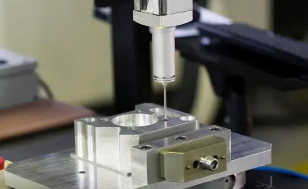
- Rapid prototyping capabilities: Speed matters during development. Partners offering quick-turn prototyping—like Shaoyi's 5-day rapid prototyping service—let you validate designs and iterate quickly without sacrificing precision. This capability proves especially valuable when you're still refining tolerances and need fast feedback.
- Quote responsiveness: A partner's quote turnaround time often reflects their operational efficiency. Shaoyi's 12-hour quote turnaround demonstrates the systematic processes and engineering depth that translate into reliable production execution. Slow quotes frequently signal slow production.
When evaluating a precision sheet metal shop inc, request capability documentation rather than accepting verbal assurances. Ask for equipment lists, measurement system certifications, and examples of similar tolerance work they've completed successfully.
Certification Standards That Matter
Certifications provide third-party verification that a supplier's quality systems meet established standards. For precision forming, certain certifications carry particular weight depending on your industry application.
- IATF 16949 (Automotive): According to certification specialists, this framework distills ISO 9001 standards into automotive-specific guidelines, doubling down on consistency, safety, and quality across automotive products. While not legally required, suppliers without this certification often find that automotive customers won't collaborate with them. Shaoyi maintains IATF 16949 certification specifically for automotive applications—covering chassis, suspension, and structural components where precision directly affects vehicle safety.
- ISO 9001: The foundation quality management standard that IATF 16949 builds upon. This certification confirms documented processes, quality controls, and continuous improvement systems are in place.
- AS9100 (Aerospace): For aerospace metal forming applications, this certification adds aviation-specific requirements to ISO 9001, addressing traceability, configuration management, and risk assessment critical for flight-critical components.
- ISO 13485 (Medical): Medical device manufacturing demands this specialized quality standard covering design controls, risk management, and regulatory compliance specific to healthcare applications.
- NADCAP: For special processes like heat treatment or non-destructive testing, NADCAP accreditation provides additional assurance of process control in aerospace and defense applications.
Certification verification is binary—a company either meets the standard or doesn't. Industry guidance confirms there are no variations in IATF 16949 certification status. Adherence to requirements proves a company's ability and commitment to limit defects while reducing waste. Request current certification documents and verify they cover the specific processes and locations that will handle your work.
Evaluation Framework for Partner Selection
Beyond certifications and capabilities, consider these practical factors when making your final selection:
- Production volume flexibility: Can the partner handle both prototype quantities and mass production? Some precision sheet metal fabricators excel at low-volume work but struggle with high-volume consistency. Others optimize for production runs but can't deliver quick-turn prototypes. The ideal partner spans this range—like operations offering everything from rapid prototyping through automated mass production.
- Engineering collaboration depth: According to manufacturing specialists, engineers should partner with clients from day one, reviewing designs for manufacturability. This collaboration minimizes errors and ensures each part performs as intended. Ask about their engineering team's experience with similar applications.
- Documented quality systems: Request information about incoming material inspection, in-process controls, and final verification procedures. Partners operating under ISO-certified quality management systems follow documented standards from material selection through final inspection.
- Communication and responsiveness: Precision problems demand quick resolution. Evaluate how potential partners handle questions during the quotation process—their responsiveness now predicts their responsiveness during production issues.
- Track record with similar applications: A partner experienced with d&v precision sheet metal work for your specific industry understands the unique challenges your components face. Ask for references and case studies from comparable projects.
Metal fabrication design software compatibility also matters. Partners using current CAD/CAM systems can work directly with your design files, reducing translation errors and accelerating the quote-to-production timeline. Confirm they can accept your native file formats without requiring extensive conversion.
The selection process ultimately comes down to matching partner capabilities with your specific precision requirements. A supplier perfectly suited for d&v precision sheet metal architectural components may not be ideal for automotive chassis brackets requiring IATF 16949 compliance. Define your non-negotiable requirements first, then evaluate partners against those specific criteria.
When precision sheet metal forming is executed correctly—with the right techniques, materials, quality controls, and manufacturing partners—the costly defects that plague standard fabrication simply don't occur. The investment in precision pays returns through eliminated rework, reduced scrap, streamlined assembly, and products that perform exactly as designed. That's the difference between parts that almost work and parts that work flawlessly, every time.
Frequently Asked Questions About Precision Sheet Metal Forming
1. What is precision sheet metal fabrication?
Precision sheet metal fabrication is a manufacturing process that shapes thin metal stock (typically 0.1mm to 3mm thick) into complex geometries while maintaining exceptionally tight dimensional tolerances of ±0.1mm or tighter. Unlike standard fabrication that accepts ±1.6mm to ±3.2mm variations, precision work requires advanced CNC equipment, sophisticated tooling, comprehensive material knowledge, and rigorous statistical process control to achieve consistent, engineering-grade results suitable for automotive, aerospace, and medical applications.
2. What are the different types of sheet metal forming processes?
The main precision forming techniques include hydroforming (for complex 3D shapes), rubber pad forming (for prototypes and shallow draws), incremental forming (for custom one-off parts), stretch forming (for large curved panels), deep drawing (for hollow shapes like cups and enclosures), and roll forming (for continuous linear profiles). Each method offers different tolerance capabilities, material compatibility, and production volume suitability, making technique selection dependent on part geometry, precision requirements, and economic factors.
3. How do you prevent defects in sheet metal forming?
Preventing forming defects requires a multi-faceted approach: verify incoming material thickness, hardness, and grain orientation before production; perform first-piece inspection on every run; establish tooling maintenance schedules based on cycle counts; implement in-process sampling with defined frequencies; and monitor shop temperature for tight-tolerance work. For specific defects like springback, use overbending compensation of 2-8 degrees; for wrinkling, increase blank holder pressure; and for cracking, ensure bend radii aren't too tight relative to material ductility.
4. What tolerance can precision sheet metal fabrication achieve?
Precision sheet metal fabrication typically achieves tolerances of ±0.1mm to ±0.05mm or tighter, as defined by ISO 2768 fine tolerance grades and ASME Y14.5 geometric dimensioning standards. Deep drawing can achieve the tightest precision at ±0.05mm to ±0.15mm, while roll forming delivers ±0.1mm to ±0.2mm for linear profiles. Achievable tolerances depend on the forming technique, material properties, equipment capabilities, and process control sophistication.
5. How do I choose a precision sheet metal fabrication partner?
Evaluate partners based on integrated manufacturing capabilities, advanced measurement systems like CMMs, CNC equipment with adaptive controls, and strong DFM support. Verify relevant certifications including IATF 16949 for automotive, AS9100 for aerospace, or ISO 13485 for medical applications. Look for rapid prototyping capabilities, responsive quote turnaround, and documented quality systems. Partners like Shaoyi (Ningbo) Metal Technology offer IATF 16949 certification, 5-day rapid prototyping, comprehensive DFM support, and 12-hour quote turnaround for automotive precision components.