 Małe partie, wysokie standardy. Nasza usługa szybkiego prototypowania sprawia, że weryfikacja jest szybsza i łatwiejsza —

Czym jest spawanie laserem? Jak działa, gdzie przewyższa inne metody i dlaczego spoiny ulegają uszkodzeniu
Czym jest spawanie laserowe – prosta definicja?
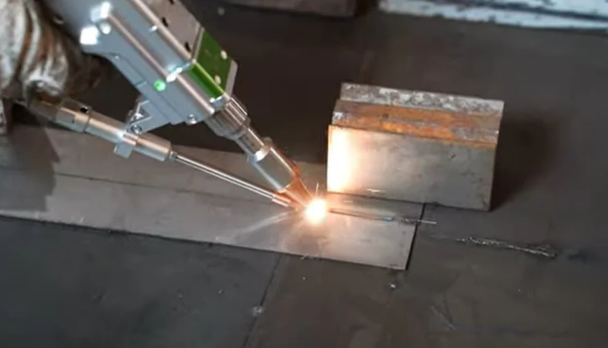
Czym jest spawanie laserowe? W uproszczeniu jest to proces łączenia materiałów, w którym do stopienia metalu w miejscu styku dwóch części wykorzystuje się silnie skupioną wiązkę światła. Gdy ta mała strefa stopienia ochładza się, elementy łączą się w jedno połączenie. Czasem można też spotkać się z określeniem spawanie wiązki laserowej lub zastanawiać się, czym jest spawanie wiązką laserową . W praktyce wszystkie te terminy odnoszą się do tej samej podstawowej koncepcji.
Spawanie laserowe polega na łączeniu materiałów poprzez skupienie energii laserowej w bardzo małym obszarze, co powoduje powstanie kontrolowanej strefy ciekłej z precyzyjnym dozowaniem ciepła.
Co oznacza spawanie laserowe
W przeciwieństwie do szerszych kategorii spawania, które obejmują wiele różnych źródeł ciepła, spawanie laserowe definiuje się właśnie przez jego źródło ciepła: skupioną wiązkę laserową. A spawarka laserowa może być częścią dużej zautomatyzowanej komórki lub przenośnego urządzenia, ale podstawowa zasada pozostaje taka sama. Promień dostarcza energii bez kontaktu fizycznego, topi wąską strefę w miejscu połączenia, a następnie materiał ten zastyga, tworząc spoinę.
- Jest to proces spawania bez kontaktu.
- Skupia ciepło w bardzo małej strefie.
- Zazwyczaj powoduje powstanie wąskich spoin oraz ograniczonej strefy wpływu ciepła.
- W niektórych przypadkach może wykorzystywać metal dodatkowy, ale nie zawsze.
- Często nadaje się do precyzyjnej i powtarzalnej pracy produkcyjnej.
Jak spawanie wiązką laserową różni się od innych metod łączenia
Ludzie czasem mylą spawanie laserowe ze cięciem laserowym, ale to nie jest to samo zadanie. Cięcie rozdziela materiał, natomiast spawanie łączy go. Różni się również od procesów łukowych, takich jak MIG lub TIG, które wykorzystują łuk elektryczny jako źródło ciepła zamiast skoncentrowanego światła. To właśnie ta różnica sprawia, że spoiny laserowe są często kojarzone z bardziej delikatnymi szwami, lepszą kontrolą ciepła oraz większą wrażliwością na dopasowanie elementów.
Dlaczego producenci stosują spawanie laserowe
Producenci rozważają tę metodę, gdy potrzebują precyzji, czystej geometrii szwu oraz sprzętu łatwo integrującego się z systemami automatyzacji. Xometry wskazuje na jej zastosowanie w takich branżach jak motocyklowa, lotnicza, medyczna i elektroniczna, gdzie kluczowe są powtarzalność oraz kontrolowane wprowadzanie ciepła. Jeśli kiedykolwiek zadawałeś sobie pytanie: czym jest spawarka laserowa , praktyczna odpowiedź jest prosta: to system generujący, przesyłający i kontrolujący skoncentrowaną wiązkę. Prawdziwa historia dotyczy jednak tego, jak ta wiązka przekształca światło w stabilny stopiony basen, a następnie w gotowy szew.
Jak przebiega spawanie laserowe krok po kroku?
Przekształcenie skoncentrowanej wiązki światła w gotowy złącze odbywa się w bardzo szybkiej sekwencji. Jeśli zadajesz sobie pytanie: jak działa spawanie laserowe lub jak działa spawanie wiązką laserową , krótką odpowiedzią jest następująca: źródło laserowe generuje wiązkę, optyka skupia ją na złączu, metal pochłania energię, tworzy się stopiony basen, który następnie krzepnie za poruszającą się wiązką, tworząc szew. Pełne proces spawania laserowego staje się znacznie łatwiejsze do śledzenia, gdy przyjmuje się je etap po etapie.
Od źródła lasera do skupionej wiązki
Praktycznym sposobem na udzielenie odpowiedzi jak działa spawarka laserowa jest podział systemu na trzy zadania: generowanie wiązki, przesyłanie wiązki oraz kontrola tego, co dzieje się w strefie połączenia. W procesie spawania laserowego spawania laserowego , te zadania zwykle realizowane są w następującej kolejności:
- Źródło lasera generuje wiązkę. Typowymi przemysłowymi źródłami są lasery włóknowe, CO₂ oraz lasery stanu stałego.
- WiĄzka jest przesyłana do głowicy spawalniczej. Lustra, soczewki i inne elementy optyczne kierują ją w stronę obszaru roboczego.
- Optyka skupiająca kurczy wiązkę do bardzo małego punktu. Skupienie energii w niewielkim obszarze umożliwia spawanie.
- Części są przygotowywane i wyrównywane. Uchwyty lub zautomatyzowane systemy utrzymują połączenie w odpowiedniej pozycji, aby wiązka trafiła dokładnie w szew.
- Gaz osłonowy chroni strefę spawania. Gazy takie jak argon lub hel pomagają utrzymać czystość stopionego metalu, ograniczając utlenianie i zanieczyszczenia.
- Metal pochłania energię laserową. Powierzchnia szybko się nagrzewa wzdłuż linii połączenia i osiąga temperaturę topnienia.
- Powstaje stopiona kałuża, która przemieszcza się. W miarę przesuwania się wiązki lub przedmiotu roboczego kałuża porusza się wzdłuż szwu, łącząc ze sobą obie krawędzie.
- Spoina krzepnie. Gdy wiązka przesuwa się dalej, ciekły metal ochładza się i zastyga, tworząc gotowy połączenie.
Jak powstaje i krzepnie wana stopiona.
Wana stopiona jest sercem procesu. Jest mała, kontrolowana i krótkotrwała. Gdy wiązka uderza w połączenie, pochłonięte światło przekształca się w ciepło. To ciepło topi metal podstawowy dokładnie w miejscu styku części. W wielu zastosowaniach nie wymaga się metalu dodatkowego, więc same materiały podstawowe tworzą spoinę. Gdy wiązka przesuwa się naprzód, czołowa część wany nadal topi nowy materiał, podczas gdy tylna część wany ochładza się i krzepnie. Dlatego też proces ten umożliwia tworzenie wąskich szwów przy bardzo lokalizowanym wpływie ciepła w porównaniu do metod wykorzystujących źródła ciepła o większym rozpraszaniu.
Tutaj kluczowe znaczenie mają czyste powierzchnie, stabilne dopasowanie połączenia oraz stała prędkość przesuwu. Najmniejsza zmiana odległości między elementami, ustawienia ostrości wiązki lub prędkości przesuwu może wpłynąć na zachowanie wany stopionej – jest to jedna z przyczyn, dla których proces spawania laserowego (LBW) charakteryzuje się dużą precyzją, ale także dużą wrażliwością na warunki przygotowania.
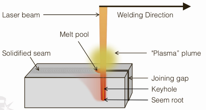
Tryb przewodzenia ciepła i tryb otworu klucza – wyjaśnienie
Spoiny przewodzeniowe są zazwyczaj płytsze i szersze, podczas gdy spoiny typu kluczkowe są głębsze i węższe, ponieważ wyższa gęstość mocy powoduje utworzenie w metalu jamy wypełnionej parą.
To właśnie w tym miejscu techniczna strona jak działa spawanie laserowe zaczyna odgrywać istotną rolę. EWI definiuje gęstość mocy jako moc lasera podzieloną przez powierzchnię skupionego plamka. Przy niższej gęstości mocy ciepło rozprasza się głównie od powierzchni do wnętrza materiału, tworząc szerszą i płytszą spoinę. Przy wyższej gęstości mocy metal może ulec odparowaniu i utworzyć małą jamę zwaną kluczkową, która umożliwia docieranie energii głębiej do połączenia.
Szczegółowe wskazówki od AMADA WELD TECH prowadzi do trybu przewodzenia wokół 0,5 MW/cm², obszaru przejściowego wokół 1 MW/cm² oraz trybu kluczkowego powyżej około 1,5 MW/cm². Ogólnie rzecz biorąc, zwiększenie gęstości energii zwykle zwiększa głębokość penetracji i zmienia kształt spoiny od płytkiego i szerokiego do głębokiego i wąskiego. Prędkość przesuwu również odgrywa istotną rolę. Wyższa prędkość zazwyczaj znacznie zmniejsza szerokość spoiny i może także obniżać głębokość penetracji, zwłaszcza jeśli wiązka nie utrzymuje już stabilności basenu stopionego.
Kolejność pozostaje taka sama, ale sposób jej tworzenia może się znacznie różnić w zależności od źródła lasera, metody dostarczania wiązki oraz tego, czy system został zaprojektowany do pracy ręcznej, czy pełnej automatyzacji.
Maszyny do spawania laserowego, źródła promieniowania i dostarczanie wiązki
Ta różnorodność zaczyna się od samego źródła. Gdy ludzie porównują maszyna do spawania laserowego porównują zwykle nie tylko surową moc. Porównują sposób tworzenia wiązki, sposób jej dostarczania do połączenia oraz łatwość dopasowania sprzętu do rzeczywistych warunków produkcyjnych. Te wybory wpływają na współczynnik absorpcji, zapotrzebowanie na konserwację, potencjał zautomatyzowania procesu oraz codzienną elastyczność w warsztacie.
Źródła laserowe: włókienkowe, CO₂ i stanu stałego
A przegląd nowoczesnego spawania wiązką laserową (LBW) wyjaśnia, że źródła laserowe stanu stałego – takie jak włókienkowe, dyskowe, półprzewodnikowe oraz Nd:YAG – emitują promieniowanie o znacznie krótszej długości fali niż lasery CO₂. W praktyce ma to istotne znaczenie z dwóch powodów. Po pierwsze, wiązki laserowe stanu stałego o krótszej długości fali są zazwyczaj lepiej pochłaniane przez wiele metali niż wiązki laserów CO₂. Po drugie, takie wiązki można przesyłać za pomocą giętkich światłowodów, co stanowi istotną zaletę przy zastosowaniu główek zdalnych, robotów oraz kompaktowych układów maszyn. Dlatego też spawanie laserem wzmocnionym włóknem jest tak ściśle związane z automatyzacją.
Ta sama recenzja zauważa, że aluminium i miedź silnie odbijają energię laserową, więc materiały odbijające nadal stanowią wyzwanie. Mimo to źródła stanu stałego są zazwyczaj lepiej dopasowane niż Spawanie Laserowe CO2 do tych zadań. Oddzielne porównanie włókna i CO₂ opisuje również układy włókniane jako bardziej zwarte i zwykle wymagające mniejszego nakładu na konserwację, podczas gdy systemy CO₂ zazwyczaj wymagają więcej miejsca, więcej energii oraz częstszej konserwacji.
| Typ źródła | Metoda dostarczania wiązki | Praktyczne zalety | Praktyczne ograniczenia | Typowe zastosowanie w produkcji |
|---|---|---|---|---|
| Włókno | Elastyczne światłowody do głowicy spawalniczej | Zwarty, przyjazny dla automatyzacji, dobra elastyczność trasowania wiązki, ogólnie lepsze pochłanianie niż w przypadku CO₂ | Nadal wrażliwe na dokładność montażu i ustawienia; metale odbijające mogą nadal stanowić trudność | Komórki robotyczne, praca precyzyjna, produkcja części mieszanych |
| CO2 | Lustra i przekazywanie wiązki optycznej | Ustalona technologia do zastosowań w stałych instalacjach i na dużą skalę | Bardziej gabarytowe układy, wyższe wymagania serwisowe i energetyczne, mniejsza elastyczność trasowania wiązki, gorsze dopasowanie do metali odbijających | Stacjonarne systemy, w których przestrzeń i elastyczność trasowania wiązki są mniej istotne |
| Inne typy laserów stanowiących ciało stałe, np. dyskowe, diodowe oraz Nd:YAG | Optyka oraz – w wielu układach – przekazywanie wiązki za pomocą światłowodów | Krótsze długości fal niż w przypadku laserów CO₂, dobre właściwości absorpcji, przydatne opcje kształtu wiązki dla niektórych zastosowań | Możliwości zależą w dużej mierze od jakości wiązki, optyki oraz projektu procesu | Specjalizowane linie zautomatyzowane oraz zadania spawalnicze dostosowane do konkretnego procesu |
Systemy przenośne oraz komórki zautomatyzowane
Typ źródła to tylko połowa historii. Format systemu zmienia sposób wykorzystania procesu. spawarka laserowa urządzenie przenośne jest zwykle wybierane do prac naprawczych, spawania nieregularnych szwów, prototypów, krótkich serii oraz zadań, w których kluczowe jest szybkie przygotowanie. Porównanie urządzeń przenośnych i robotycznych określa jednostki przenośne jako elastyczne, łatwe w uruchomieniu oraz przydatne w ciasnych lub trudno dostępnych miejscach.
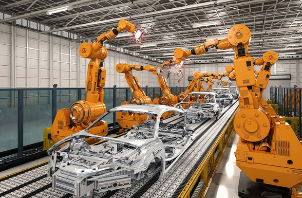
Zautomatyzowane systemy spawania laserowego urządzenia robotyczne są zaprojektowane z myślą o innym rytmie pracy. Opierają się na zaprogramowanych trajektoriach ruchu, uchwytach, czujnikach oraz obudowach bezpieczeństwa, aby zapewnić powtarzalne spawanie w wielu cyklach. spawanie laserowe włókna optycznego laser typu fiber może przesyłać wiązkę przez elastyczny kabel do głowicy zamontowanej na roboty, co czyni go szczególnie odpowiednim dla produkcji z wykorzystaniem robotów. Natomiast układy laserowe CO₂ z odbiciem wiązki za pomocą luster są mniej wygodne, gdy ścieżka wiązki musi omijać zatłoczoną komórkę robota.
W jaki sposób wybór sprzętu wpływa na wynik spawania
Różny maszyny do spawania laserowego może generować bardzo różne zachowania spoiny już przed dostosowaniem ustawień. Ręczne narzędzie może zapewnić lepszy dostęp do trudnego połączenia. Komórka zautomatyzowana może zapewniać większą stałość ścieżki ruchu głowicy i odległości od powierzchni. Kompaktowy system włókien optycznych może uprościć integrację z robotem, podczas gdy większy układ CO2 może wymagać bardziej szczegółowego planowania układu przestrzennego i intensywniejszej konserwacji. Innymi słowy wybór sprzętu sam w sobie nie gwarantuje jakości spoiny, ale wyznacza granice tego, co proces może osiągnąć w sposób niezawodny. Te granice stają się widoczne na kolejnym poziomie decyzji: moc, średnica plamki lasera, położenie ogniska, prędkość, zabezpieczenie gazem oraz precyzja dopasowania elementów.
Ustawienia spawania laserowego wpływające na jakość spoiny
Sprzęt tworzy możliwości. Ustawienia decydują o tym, czy te możliwości przekształcą się w solidne połączenie. Jeśli zastanawiasz się, czy spawanie laserowe jest wytrzymałe , praktyczna odpowiedź brzmi: tak – pod warunkiem, że konfiguracja zapewnia pełne stopienie materiału i unika wad. Innymi słowy, wytrzymałość spawania laserowego wynika z kontrolowanej energii, stabilnych warunków połączenia i czystej dyscypliny procesowej, a nie wyłącznie z nazwy wiązki.
Rozmiar punktu mocy i położenie ogniska
Moc to ilość energii laserowej dostępnej do stopienia połączenia. Wielkość miejsca określa, jak ściśle ta energia jest skoncentrowana. Pozycja ogniska to położenie najmniejszej i najbardziej intensywnej części wiązki względem powierzchni obrabianej. W trakcie Przeglądu spawania wiązką laserową (LBW) , przesunięcie ogniska powyżej lub poniżej optymalnego położenia obniża rzeczywistą gęstość mocy, zmienia kształt śladu spoiny, poszerza spoinę i zmniejsza głębokość wtopienia. Dlatego też dwa ustawienia o podobnej mocy mogą generować bardzo różne głębokości wtopienia spoiny laserowej .
Tryb wiązki ma również znaczenie. Wśród głównych typów spawania laserowego , tryb przewodzenia wykorzystuje niższą gęstość energii i zazwyczaj powoduje płytsze oraz szersze spoiny. Spawanie laserowe w trybie klucza wykorzystuje wyższą gęstość energii, aby uzyskać głębsze i węższe połączenie topione. Przewodnik Laserax wyjaśnia również, dlaczego rozmiar plamki jest tak czułym parametrem: mniejsza plamka zwiększa natężenie i głębokość wnikania, ale wymaga również dokładniejszego pozycjonowania i dopasowania elementów. Większa plamka rozprasza ciepło na szerszym obszarze, co może pomóc przy niektórych typach połączeń, ale zwykle zmniejsza głębokość spoiny.
Prędkość przesuwu, gaz osłonowy i dopasowanie elementów
Prędkość jazdy określają, jak długo wiązka pozostaje nad każdym odcinkiem szwu. Zgodnie z tym samym przeglądem zwiększenie prędkości przy stałej mocy sprawia, że spoina staje się węższa i zazwyczaj płytsza. Przekroczenie dopuszczalnej prędkości może prowadzić do braku wniknięcia lub braku zlania się materiałów. Zbyt niska prędkość powoduje nagromadzenie ciepła, co zwiększa szerokość grzbietu spoiny, ryzyko odkształceń, przepływu stopu lub przebitia.
Gaz osłonowy chroni stopioną kałużę i pomaga kontrolować chmurę plazmy. Zarówno przewodnik Laserax, jak i przewodnik rozwiązywania problemów GWK wiążą słabe zabezpieczenie gazem z utlenianiem, porowatością oraz niestabilnymi spoinami. Zbyt mała ilość gazu pozwala na zanieczyszczenie. Zbyt duża ilość może wywołać turbulencje lub zakłócić kałużę, jeśli dysza jest źle skierowana.
Dopasowanie krawędzi spawanych oznacza, jak dokładnie części przylegają do siebie. Wyroby utrzymuje je w tym położeniu. Czystość powierzchni usuwa tlenki, olej, rdzę, farbę, warstwę skaleń oraz wilgoć. Brzmi to podstawowo, ale technologia spawania laserowego nie jest tutaj bardzo wyrozumiały. W materiałach technicznych Laserax podano typową zasadę dotyczącą spoiny nakładkowej, zgodnie z którą dopuszczalna szczelina nie powinna przekraczać około 10–20% grubości cieńszej blachy; w wielu zastosowaniach kontrola szczeliny musi pozostać poniżej 0,1 mm. Brudne lub otwarte spoiny często powodują te same problemy, które operatorzy próbują rozwiązać poprzez zmianę mocy.
Wpływ wyborów parametrów ustawienia na głębokość przetopu i jakość grzbietu spoiny
| Zmienna | Co to znaczy | Co się dzieje, gdy wartość jest zbyt niska | Co się dzieje, gdy wartość jest zbyt wysoka | Jak operator zwykle reaguje |
|---|---|---|---|---|
| Moc | Całkowita energia dostępna do stopienia połączenia | Płytkie spawanie, brak zlania, słabe wnikanie | Rozpryski, podcięcia, przeżarcia, szersza strefa wpływu ciepła (HAZ) | Dostosuj moc małymi krokami i zweryfikuj na przekrojach lub testach |
| Wielkość miejsca | Średnica skupionej wiązki na elemencie | Zbyt duża plama może rozpraszać ciepło i zmniejszać głębokość wnikania | Zbyt mała plama może stać się nadmiernie intensywna i trudna do precyzyjnego umieszczenia | Zmień optykę, ponownie sfokusuj lub zastosuj oscylację, aby dopasować się do połączenia |
| Pozycja ogniska | Położenie optymalnego punktu fokusu względem powierzchni lub połączenia | Wiązka rozdefokusowana powyżej lub z dala od połączenia zmniejsza natężenie i wnikanie | Zbyt głębokie lub nieodpowiednio umieszczone punkty skupienia mogą zdestabilizować proces lub zmienić kształt spoiny | Przesuń punkt skupienia w kierunku powierzchni lub lekko do wnętrza połączenia, w razie potrzeby |
| Tryb wiązki | Sposób dostarczania energii, np. przewodzenie vs. kluczowe (keyhole), ciągły (CW) vs. impulsowy lub modulowany | Tryb jest zbyt łagodny dla połączenia, co powoduje płytkie zespolenie | Tryb jest zbyt agresywny, powodując niestabilne zachowanie klucza (keyhole) lub przegrzanie | Zmień tryb lub dostosuj modulację, impulsy lub wzór oscylacji |
| Prędkość jazdy | Prędkość przesuwania wiązki wzdłuż szwu | Zbyt niska prędkość zwiększa wprowadzaną ilość ciepła, szerokość spoiny oraz ryzyko odkształceń | Zbyt wysoka prędkość zmniejsza stopień zespolenia i wnikanie | Dobierz prędkość w stosunku do mocy, a następnie sprawdź kształt spoiny oraz zespolenie w korzeniu |
| Gaz osłonowy | Rodzaj gazu, przepływ i położenie dyszy wokół strefy spawania | Utlenianie, porowatość, przebarwienia, niestabilny proces | Turbulencja, zakłócenia w wannie spawalniczej, niestała ochrona gazowa | Poprawny wybór gazu, odległość dyszy od powierzchni, kąt nachylenia dyszy oraz umiarkowany przepływ gazu |
| Dopasowanie krawędzi spawanych | Jak dokładnie części stykają się ze sobą | Otwarte szczeliny powodują niepełne zespolenie i niestabilne wnikanie | Zbyt duże dociskanie może prowadzić do problemów z wyjustowaniem lub naprężeń podczas dokręcania uchwytów | Ulepszyć przygotowanie części, zmniejszyć szczeliny lub przeprojektować połączenie w razie potrzeby |
| Wyroby | Jak mocno części są utrzymywane podczas spawania i chłodzenia | Ruch, przesuwanie się szczelin, odkształcenia, nieregularne śledzenie szwu | Przeciążenie może utrudnić załadunek lub spowodować naprężenia lokalne | Używaj stabilnych uchwytów i podpieraj cienkie przekroje lub krawędzie |
| Czystość powierzchni | Stan powierzchni styku przed spawaniem | Zanieczyszczenia zatrzymują gaz, obniżają pochłanianie energii i zwiększają ryzyko wad | Nadmierny oczyszczanie jest zwykle mniej szkodliwe niż niedostateczne oczyszczanie, ale może marnować czas | Usuń olej, rdzę, farbę, warstwę skaleń i tlenki tuż przed spawaniem |
- Upewnij się, że połączenie jest czyste i suche przed pierwszym przyspawaniem lub pierwszym przebiegiem.
- Sprawdź kontrolę szczeliny i nacisk uchwytów przed zmianą mocy.
- Zweryfikuj położenie punktu ogniskowania i wyrównanie dyszy w rzeczywistym miejscu spawania.
- Zmieniaj tylko jedną zmienną naraz podczas strojenia lub rozwiązywania problemów.
- Zweryfikuj wyniki za pomocą przekrojów, testów rozciągania lub innych metod inspekcji.
To jest rzeczywisty wzór leżący u podstaw technologia spawania laserowego : każda ustawiona wartość zmienia wielkość, głębokość i stabilność basenu ciekłego metalu, a zmienne te oddziałują ze sobą. Procedura, która doskonale sprawdza się dla jednego stopu, może zachowywać się zupełnie inaczej w przypadku innego stopu — właśnie dlatego wybór materiału zasługuje na osobne, szczegółowe rozważenie.
Przewodnik po spawaniu laserowym metali i dopasowaniu krawędzi spawanych
Materiał zmienia wszystko. Ustawienie, które działa bez zarzutu przy stali, może okazać się nieskuteczne przy miedzi, a solidny spaw czołowy może się rozpaść, jeśli ten sam materiał zostanie użyty do spawania nakładkowego z luźnym dopasowaniem krawędzi. Dlatego wybór metalu, stan powierzchni oraz dokładność dopasowania krawędzi muszą być oceniane łącznie. W spawaniu laserowym najważniejsze pytania dotyczące materiału są proste: jak dobrze metal pochłania wiązkę laserową, jak szybko odprowadza ciepło, jak wrażliwy jest na zanieczyszczenia oraz co dzieje się w przypadku otwarcia się szczeliny spawalniczej?
Stal nierdzewna i stal węglowa
Stal nierdzewna jest zazwyczaj jednym z łatwiejszych materiałów do spawania laserem. W codziennej produkcji spawanie laserem stali nierdzewnej jest cenione, ponieważ skoncentrowane ciepło pozwala ograniczyć odkształcenia blach, rur oraz precyzyjnych elementów. Wadą jest to, że stal nierdzewna nadal surowo karze słabe osłonięcie gazem i brudne powierzchnie. Utlenianie od strony tylniej, przebarwienia oraz obniżona odporność korozyjna mogą wystąpić w przypadku utraty kontroli nad temperaturą lub niewłaściowego zabezpieczenia gazem.
Stal węglowa również stanowi dobry materiał do spawania laserem. Ogólnie lepiej absorbuje energię laserową niż metale o wysokiej odbijalności, dzięki czemu stabilność procesu jest łatwiejsza do osiągnięcia. W przypadku cienkich przekrojów niższe wprowadzanie ciepła może pomóc zmniejszyć ryzyko przebicia i konieczności poprawek w porównaniu do szerokich procesów łukowych. Niemniej jednak stal węglowa nie toleruje szczelin. Zanieczyszczenia, uwięziony gaz oraz niestabilny stan krawędzi nadal mogą powodować porowatość lub brak zlania.
Aluminium, miedź i tytan
Aluminium i miedź są bardziej wymagające, ponieważ oba materiały odbijają dużą część padającej energii laserowej i szybko odprowadzają ciepło. Opublikowane dane dotyczące odbijalności dla typowych długości fal podczerwonych wskazują na wartość bliską 0,99 dla miedzi i bliską 0,91 dla aluminium – znacznie wyższe niż dla żelaza i tytanu. Dlatego też spawanie aluminium laserem zwykle wymaga ścislejszej kontroli procesu niż spawanie stali. Tlenki powierzchniowe, oleje i wilgoć mają większy wpływ, a porowatość związana z wodorem staje się istotnym problemem. W przypadku zakładów spawających aluminium 6061 , staranne czyszczenie, dopasowanie elementów do siebie oraz kontrola wiązki laserowej są zwykle równie ważne co surowa moc.
Miedź stwarza dodatkowe wyzwanie, ponieważ tak szybko odprowadza ciepło, że inicjacja spoiny może być niestabilna. Kluczowe stają się więc precyzyjne skupienie wiązki oraz stabilne ustawienie układu. Tytan znajduje się po przeciwnej stronie mapy problemów. Absorbuje on energię laserową stosunkowo dobrze, więc spawanie tytanu laserem może tworzyć precyzyjne spoiny z małą strefą wpływu ciepła. Problemem jest reaktywność. Gorący tytan łatwo wchłania tlen, azot i wodór, dlatego jakość osłony musi być stale doskonała, w przeciwnym razie spoina może szybko ulec odmęczeniu.
Projektowanie połączeń metali różnorodnych oraz uwzględnienie materiału dodatkowego
Stal ocynkowana nadaje się do spawania, ale powłoka cynkowa zmienia zasady. Cynk topi się i paruje wcześniej niż podstawowa stal, co może prowadzić do powstawania oparów, porowatości, wtrąceń tlenków oraz utraty powłoki. Uwagi dotyczące spawania stali ocynkowanej wyjaśniają również, dlaczego okna procesowe zależą w dużej mierze od grubości materiału i konfiguracji układu. Publikowane przykłady zastosowania ręcznych źródeł ciepła dotyczą najczęściej blach o grubości około 1–2 mm, podczas gdy przy użyciu źródeł o wyższej mocy w jednoprzelotowym spawaniu można osiągnąć grubość około 5–6 mm w określonych warunkach. W praktyce połączenia nakładkowe na blachach z powłoką wymagają szczególnej ostrożności, ponieważ para może gromadzić się na styku.
Połączenia różnorodne wymagają jeszcze większej ostrożności. Jeśli zapytasz, czy można spawać stal węglową ze stalą nierdzewną , praktyczną odpowiedzią jest czasem „tak”, ale metallurgię i rozcieńczenie należy kontrolować z należytą starannością, a metal wypełniający może być pomocny. Jeśli pytanie dotyczy czy można spawać tytan ze stalą , jest to znacznie trudniejszy przypadek, ponieważ łatwo mogą tworzyć się kruche związki międzymetaliczne. Te same ostrożności dotyczą również spawania laserowego aluminium ze stalą . Te połączenia mogą wymagać metalu wypełniającego, warstw przejściowych, powłok lub nawet innego procesu, takiego jak spawanie laserowe metodą lutowania miękkiego zamiast bezpośredniego stopienia.
Geometria połączenia ma takie samo znaczenie jak skład chemiczny. Wskazówki dotyczące projektowania połączeń zwykle zalecają połączenia czołowe w celu uzyskania czystej penetracji, podczas gdy połączenia nakładkowe, krawędziowe i te typu T stawiają większe wymagania w zakresie dostępu wiązki, docisku i kontroli szczeliny. Spawanie laserowe umożliwia skuteczne łączenie wielu metali, jednak najlepsze efekty daje przy precyzyjnie dopasowanych krawędziach, czystych powierzchniach oraz konstrukcji, która nie wymaga od wiązki „mostowania” niedoskonałego dopasowania elementów.
| Materiał | Ogólna przydatność | Powszechne wyzwania | Wrażliwość na dopasowanie połączenia | Uwagi szczególne dotyczące procesu |
|---|---|---|---|---|
| Stal nierdzewna | Wysoki | Utlenianie, przebarwienia, cukrzycowanie strony odwrotnej, utrata materiału wskutek korozji przy słabej ochronie | Średni do wysoki | Czyste powierzchnie i skuteczna ochrona są ważne, szczególnie w przypadku cienkich lub elementów estetycznych |
| Stal węglowa | Wysoki | Porowatość spowodowana zanieczyszczeniem, przepalenie w cienkich przekrojach, brak zlania się przy otwartych szczelinach | Średni do wysoki | Zazwyczaj lepiej pochłania energię laserową niż aluminium lub miedź, ale nadal wymaga dokładnego dopasowania |
| Stopy aluminium | Umiarkowany do wysokiego | Wysoka odbijalność, wysoka przewodność cieplna, warstwa tlenkowa, porowatość wodorowa | Wysoki | Popularne stopy, takie jak 6061, można spawać, ale przygotowanie i kontrola parametrów są kluczowe |
| Miedź i jej legity | Umiarkowany | Bardzo wysoka odbijalność, szybka utrata ciepła, niestabilny początek spawania | Wysoki | Najlepiej nadaje się do ściśle kontrolowanych układów i precyzyjnego skupiania wiązki |
| Tytan | Wysoka przy odpowiedniej ochronie | Zanieczyszczenie, kruchość, przebarwienia, jeśli nagrzany metal narażony jest na działanie powietrza | Wysoki | Doskonała ochrona gazowa jest obowiązkowa przed, podczas oraz tuż po przeprowadzeniu szwu spawalniczego |
| Stal galwanizowana | Umiarkowany do wysokiego | Parowanie cynku, opary, porowatość, wtrącenia tlenków, uszkodzenie powłoki | Wysokie, szczególnie w połączeniach nakładkowych | Wentylacja i kontrola parametrów są istotne, ponieważ warstwa cynku reaguje wcześniej niż rdzeń stalowy |
| Pary metali różnorodnych | Przypadek od przypadku | Fazy międzymetaliczne, nieregularne pochłanianie energii, nierównomierne rozszerzanie się oraz ryzyko pęknięć | Bardzo wysoki | Może być konieczne zastosowanie drutu spawalniczego, warstw przejściowych, powłok lub alternatywnych metod łączenia |
Obudowa ze stali nierdzewnej, implant tytanowy oraz ocynkowana blacha samochodowa mogą być wszystkie spawalne, ale nie stawiają one tych samych wymagań wobec procesu. Zgodność materiałów stanowi jedynie połowę decyzji. Dokładność, szybkość, dostępność, dopuszczalna szerokość szczeliny oraz objętość produkcji decydują o tym, czy spawanie laserowe jest najlepszym rozwiązaniem, czy też bardziej uzasadnione są metody takie jak spawanie TIG, MIG, spawanie punktowe lub inne metody.
Zalety i ograniczenia spawania laserowego w porównaniu z innymi metodami łączenia
Metalu można spawać laserem, a mimo to nie nadaje się do tego. To jest prawdziwy punkt decyzyjny. Wybór procesu nie polega tylko na tym, czy wiązka może tworzyć złącze. Chodzi o to, czy ta metoda odpowiada geometrii części, dopasowaniu, wielkości produkcji i oczekiwaniom końcowym. Niedawny przewodnik Fox Valley ocenia laser jako wysoce skuteczny w kontroli zniekształceń, wyglądzie kosmetycznym i prędkości na długich szwach, podczas gdy MIG jest bardziej wyrozumiały dla większych zespołów, a TIG jest wolniejszy, ale doskonały dla precyzyjnych, Wniosek Porównanie urządzeń EBM dodał inny duży kontrast: spawanie wiązką elektronów może zapewnić głębsze penetracje, ale przynosi złożoność próżni i wyższe koszty początkowe.
W przypadku spawania laserowego istnieje wyraźna przewaga
Główne zalety spawania laserowego pojawiają się, gdy łącze wymaga ściśle kontrolowanego ciepła, powtarzalności i wąskiego profilu spawania. Dlatego też często wybierany jest ten proces w przypadku cienkich blach, widocznych szwów i automatycznych ogniw produkcyjnych. Złącza ciągłe, takie jak: spawanie laserem szwów spawanie obudów, uchwytów i precyzyjnych zespołów są typowymi przykładami. Takie spawanie laserem podejście może również okazać się uzasadnione w przypadku potrzeby tylko małych, lokalizowanych połączeń, zwłaszcza tam, gdzie dostęp łuku jest utrudniony.
Zalety
- Niski, skoncentrowany dopływ ciepła w porównaniu do szerokich procesów łukowych, co pomaga ograniczyć odkształcenia.
- Doskonałe rozwiązanie dla estetycznych szwów oraz elementów, które nie wymagają praktycznie żadnej obróbki końcowej.
- Wysoka prędkość spawania długich szwów przy odpowiednim materiale i zakresie grubości.
- Doskonała kompatybilność z robotyką oraz zautomatyzowaną kontrolą toru ruchu.
- Przydatne w przypadku małych, precyzyjnych stref spawania, gdzie szeroki wypływ spoiny stanowiłby problem.
Wady
- Bardziej wrażliwe na luz w szczelinie połączenia, dokładność pozycjonowania oraz stan powierzchni niż spawanie MIG.
- Koszt sprzętu jest zazwyczaj wyższy niż w przypadku podstawowych układów łukowych.
- Nie zawsze najbardziej opłacalna metoda dla grubszych elementów, połączeń z dużymi szczelinami lub bardzo zmiennych zestawień.
- Błędy parametrów mogą szybko objawić się brakiem spoiny, niedosprawieniem lub przeżarciem.
Gdzie inne metody spajania mogą być lepszym wyborem
Spawanie MIG jest często praktycznym wyborem, gdy połączenie ma charakter konstrukcyjny, zestawienie jest większe lub dopasowanie elementów jest mniej precyzyjne. Źródło Fox Valley określa tę metodę jako opłacalną i wyrozumiałą w sytuacjach, w których ważniejsze są szczeliny i szybkość niż doskonała estetyka. Spawanie TIG znajduje się na przeciwległym końcu skali kontroli ręcznej: jest wolniejsze, ale zapewnia operatorowi doskonałą kontrolę oraz bardzo czyste spoiny – dlatego nadal cieszy się popularnością przy małych partiach, pracach naprawczych oraz szczegółach, w których kluczowe jest wykończenie estetyczne.
Spawanie oporowe punktowe uzasadnia swoje zastosowanie wtedy, gdy nakładające się blachy wymagają jedynie dyskretnych punktów spoiny spawanie punktowe a nie ciągłej szwy. Innymi słowy, jeśli projekt zakłada stosowanie punktów zamiast linii, proces spawania oporowego może okazać się prostszy niż przygotowanie pełnego spawanie laserem szwów spawanie hybrydowe warto rozważyć, gdy warsztat chce skorzystać z niektórych zalet spawania laserowego, ale potrzebuje większej zdolności mostowania szczelin lub wsparcia materiału dodatkowego niż czyste spawanie laserowe zapewnia w sposób komfortowy. W przypadku niektórych elementów powlekanych lub wymagających szczególnej dbałości o wygląd, laserowe Spawanie Miękkie może zostać rozważone zamiast pełnego spawania topnego.
W spawanie wiązką laserową vs. spawanie wiązką elektronową , granicę między tymi technikami wyznaczają zwykle głębokość penetracji, wymagania dotyczące próżni oraz elastyczność produkcyjna. Spawanie wiązką elektronową charakteryzuje się bardzo dużą głębokością penetracji i wysoką precyzją, jednak ta sama źródłowa dokumentacja EBM podkreśla, że zwykle wymaga ono komory próżniowej. Systemy laserowe nie wymagają tego, co ułatwia ich integrację w standardowych układach fabrycznych oraz liniach zautomatyzowanych.
Spawanie laserowe w porównaniu ze spawaniem TIG, MIG, punktowym oraz wiązką elektronową
| Proces | Prędkość | Nakład ciepła | Precyzja i dostępność | Wrażliwość na dopasowanie elementów | Kompatybilność z automatyką | Intensywność kapitałowa | Typowe zastosowanie |
|---|---|---|---|---|---|---|---|
| Spawanie laserowe | Wysoka – przy długich szwach | Niska i skoncentrowana | Wysoka precyzja, odpowiednie do wąskich spoin | Wysoki | Wysoki | Wysoki | Cienkie blachy, spoiny estetyczne, komórki zautomatyzowane, części precyzyjne |
| Złóżka TIG | Niski | Umiarkowana i kontrolowana | Bardzo wysoki stopień kontroli przez operatora | Średni | Średni | Niski do średni | Małe serie, naprawy, ręczna praca estetyczna |
| Włókno MIG | Wysoki | Wyższa niż przy spawaniu laserowym | Umiarkowana, lepsza dla większych zespołów | Niższy niż laser | Wysoki | Średni | Części konstrukcyjne, większe spawane zespoły, produkcja przy zmiennej dokładności dopasowania |
| Spawanie punktowe oporowe | Bardzo wysoka na pojedynczy punkt spawania | Lokalizowane | Najlepsze do spawania nakładających się na siebie blach w wyodrębnionych punktach | Średni | Bardzo wysoki | Średni do wysoki | Zespolone elementy blachy, powtarzalne połączenia punktowe |
| Spawanie hybrydowe | Wysoki | Umiarkowany | Dobre tam, gdzie sam laser jest zbyt wąski lub niewielkość tolerancji nie pozwala na jego zastosowanie | Niższe niż przy czystym spawaniu laserowym | Wysoki | Wysoki | Zastosowania wymagające większej tolerancji szczelin przy wysokiej wydajności |
| Spawanie wiązką elektronów | Wysokie w odpowiednich konfiguracjach | Bardzo skoncentrowane | Bardzo wysoka precyzja i głęboka penetracja | Wysoki | Wysokie w systemach dedykowanych | Bardzo wysoki | Kluczowe połączenia o wysokiej integralności oraz grubsze przekroje w produkcji umożliwiającej pracę w warunkach próżni |
Jeszcze jedna różnica ma znaczenie dla osób niespecjalistycznych: spawanie vs lutowanie nie jest tylko różnicą temperatury. Jeśli zespół zada pytanie: jaka jest różnica między lutowaniem a spawaniem , prosta odpowiedź brzmi: spawanie polega na stopieniu materiałów podstawowych, podczas gdy lutowanie łączy elementy za pomocą stopu o niższej temperaturze topnienia bez topienia samego metalu podstawowego. Dlatego lutowanie nadaje się do połączeń elektrycznych i lekkich, ale nie zastępuje spawania konstrukcyjnego.
- Najlepsze zastosowanie dla spawania laserowego: dokładne dopasowanie elementów, cienkie do średnich grubości materiału, widoczne szwy, powtarzalna produkcja, komórki robotyczne oraz części, w których istotne jest minimalne odkształcenie.
- Niewłaściwe zastosowanie dla spawania laserowego: duże szczeliny, niestabilna przygotowka, bardzo grube przekroje wymagające ekstremalnej głębokości penetracji lub zadania, w których prosty proces ręczny jest bardziej opłacalny.
- Przypadki pograniczne: spawane połączenia lokalizowane mogą sprzyjać spawanie laserem podczas gdy blacha powlekana lub połączenia o wyglądzie mogą wskazywać w kierunku laserowe Spawanie Miękkie lub strategię hybrydową.
Najbardziej rozczarowujące wyniki spawania nie są tajemnicą. Zazwyczaj wynikają one z niewłaściwego dopasowania procesu, stanu połączenia i wprowadzonej energii. To właśnie tam zaczynają się widoczne objawy: porowatość, pęknięcia, brak zlania oraz rozpryski.
Wady spawania laserowego
Ostrzegawcze sygnały są zwykle widoczne już przed wystąpieniem wadliwego połączenia w trakcie badań. W spawaniu laserowym wady rzadko pojawiają się nagle, bez przyczyny. Zazwyczaj wynikają one z krótkiej listy kontrolowanych czynników: niestabilnej energii w strefie szwu, zabrudzonego materiału, niewystarczającej ochrony gazowej, uszkodzonych optyk lub niestabilnego dopasowania elementów. Poniższe wzorce objawów ściśle korelują z przewodniku dotyczącym wad , analizą karoserii (BIW) oraz z przewodnikiem dotyczącym problemów jakości .
Większość wad spawania laserowego wynika z czterech podstawowych czynników: gęstości energii, czystości materiału, ochrony gazowej oraz kontroli połączenia.
Porowatość, pęknięcia i niedospanie
Szybkie definicja porowatości spawania chodzi o to, że gaz zostaje uwięziony w stopionej wiązce i zamarza tworząc małe puste przestrzenie. W materiałach referencyjnych porowatość wiązana jest z brudnymi powierzchniami, parą cynku pochodzącą ze stali ocynkowanej, nieodpowiednim kierunkiem przepływu gazu osłonowego oraz głębokimi, szybko stygnącymi szwami, w których gaz nie ma wystarczająco dużo czasu, aby się uwolnić. Niestabilność klucza (keyhole) może pogłębiać ten problem.
Pęknięcie to inny rodzaj uszkodzenia. Jeśli obserwujesz pękanie spawów podczas stygnięcia, materiały referencyjne wskazują na naprężenia skurczowe powstające przed pełnym zakrzepnięciem, szybkie stygnięcie oraz materiały podatne na pękanie, takie jak stal wysokowęglowa lub stopy hartowane. Praktyczne sposoby zapobiegania obejmują nagrzewanie wstępne, kontrolowane stygnięcie oraz w niektórych przypadkach zastosowanie drutu wypełniającego w celu zmniejszenia naprężeń skurczowych.
Niedosprawienie (brak materiału w spawie) zwykle objawia się zapadniętą szwem, niskim grzbietem lub lokalnym zagłębieniem. Ten objaw często wynika z niestabilnego podawania drutu, nieprecyzyjnego umieszczenia wiązki lub niewłaściwej kombinacji prędkości i mocy, która powoduje niedobór metalu w spawie. Może również występować, gdy plamka światła przesuwa się z prawdziwego środka połączenia.
Brak zgrania, brak wnikania i przepalenie
Brak wnikania i brak zgrania często są mylone na linii produkcyjnej, ale opisują nieco inne zjawiska. Brak wnikania oznacza, że spoina nie przenika wystarczająco głęboko przez połączenie. Brak zgrania oznacza, że część powierzchni styku lub ścianki bocznej połączenia nigdy rzeczywiście nie stopiła się ze sobą. W odniesieniu do nadwozia (BIW) oba te defekty wiązane są z niską energią lasera w strefie spawania, co najczęściej wynika z zbyt niskiej mocy, zanieczyszczonej lub uszkodzonej soczewki ochronnej, niewłaściwego ustawienia punktu skupienia lub nieprawidłowego kąta wiązki.
Przepalenie to problem odwrotny. Oznacza nadmierny dopływ ciepła w stosunku do warunków połączenia, wskutek czego roztopiona kałużka przepala się przez element roboczy. W materiałach BIW zaznaczono, że jeśli przepalenie występuje tylko w pierwszej warstwie, przyczyną może być nadmierny luz między płytami. Jeśli natomiast cała spoina jest przepalona, najprawdopodobniej zestaw parametrów jest nieodpowiedni. Ta sama analiza BIW zaleca utrzymywanie luzu między płytami poniżej 0,2 mm jako długoterminową metodę kontroli dla tego zastosowania.
Zbyt duży bryzgi spawalnicze jest jednym z najłatwiejszych do wykrycia wad. Odwołania łączą ją z niewłaściwym oczyszczaniem, obecnością oleju lub zanieczyszczeń powierzchniowych, powłokami cynkowymi oraz zbyt wysoką gęstością mocy. W językach wyszukiwania często pojawia się ona jako rozpryski spawalnicze problemem, ale przyczynami leżącymi u podstaw są zwykle niestabilność procesu i stan powierzchni, a nie jakakolwiek tajemnicza, oddzielna wada.
| Wada | Jak to wygląda | Prawdopodobne przyczyny | Działania korygujące |
|---|---|---|---|
| Porowatość | Otworki, porowatość lub wewnętrzne puste przestrzenie gazowe w szwie | Brudne powierzchnie, para cynku, niewłaściwe kierowanie lub osłona gazem ochronnym, głęboki i wąski basen stopiony, niestabilny klucz | Starannie oczyścić złącze, poprawić kierunek przepływu gazu i ustawienie dyszy, ostrożnie obsługiwać materiały powlekane, ustabilizować moc i prędkość przesuwu |
| Pęknięcia | Pęknięcia liniowe w szwie lub w jego pobliżu, często po ochłodzeniu | Wysokie naprężenia skurczowe, szybkie chłodzenie, materiał podatny na pękanie | Stosować nagrzewanie wstępnego tam, gdzie jest to konieczne, zwolnić chłodzenie, zmniejszyć ograniczenia i rozważyć zastosowanie drutu wypełniającego, jeśli jest to uzasadnione |
| Niedopełnienie | Wklęsły wałek spawu, niski grzbiet lub lokalne zagłębienie spawu | Niezgodność podawania drutu, plama nie jest wyśrodkowana na szwie, prędkość zbyt wysoka, energia zbyt niska | Wyśrodkuj wiązkę, zsynchronizuj podawanie drutu, nieznacznie zwiększ skuteczną energię szwu lub zmniejsz prędkość przesuwu |
| Brak wnikania | Płytkie spawanie, nie sięgające korzenia | Niska moc, nadmierna prędkość, błędna pozycja ogniska, zabrudzona soczewka ochronna | Zwiększ użyteczną energię na szwie, zmniejsz prędkość przesuwu, sprawdź położenie ogniska oraz sprawdź lub wymień soczewkę ochronną |
| Brak przetopienia | Linia połączenia lub ścianka boczna pozostają nierozgrzane | Wiązka poza osią, błędny kąt padania, duży lub nieregularny luz, niedostateczne przygotowanie połączenia | Wyjustuj wiązkę względem szwu, skoryguj kąt głowicy, popraw dopasowanie i zaciskanie elementów oraz potwierdź stałość luzu |
| Przebarwienie | Otworki, silne przewisnięcie lub wypływ metalu przez połączenie | Zbyt duże wprowadzenie ciepła, niska prędkość przesuwu, nadmierny luz, nagromadzenie ciepła | Zmniejsz moc lub zwiększ prędkość, dokręć kontrolę szczeliny, popraw zamocowanie i sprawdź, czy element można naprawić |
| Zbyt intensywne iskrzenie | Cząstki metalu wokół szwu, zabrudzone optyka, chropowata powierzchnia | Zanieczyszczenie, para powłoki cynkowej, nadmierna gęstość mocy, niestabilny basen ciekły | Wyczyść przedmiot obrabiany, w razie potrzeby zmniejsz gęstość energii, sprawdź stabilność przepływu gazu i położenia ogniska oraz zabezpiecz soczewkę przed rozpryskami |
Działania korygujące poprawiające spójność spawania
Gdy pojawia się wada, jednoczesna zmiana kilku parametrów zwykle ukrywa rzeczywistą przyczynę. Lepsza metoda diagnozowania jest prosta i powtarzalna:
- Najpierw wyczyść strefę połączenia, obszar dyszy oraz ochronną soczewkę.
- Sprawdź rodzaj gazu, kierunek przepływu gazu, kąt nachylenia dyszy oraz odległość roboczą.
- Sprawdź położenie ogniska, centrowanie wiązki oraz kąt głowicy spawalniczej.
- Dopiero wtedy dostosuj ponownie moc, prędkość, parametry impulsu lub drgania oraz podawanie drutu.
- Potwierdź kontrolę luzów, zaciskanie i powtarzalność części przed zatwierdzeniem receptury.
Kolejność tych czynności ma znaczenie, ponieważ wiele tzw. problemów z parametrami zaczyna się jako problemy przygotowawcze. Gdy wady nadal pojawiają się mimo pozornie poprawnej receptury spawania, problem często wykracza poza pojedynczy szew. Zaczyna się on dotyczyć uchwytów, kontroli procesu, walidacji oraz decyzji, czy dane zadanie powinno być realizowane wewnętrznie, czy też przez specjalistycznego wykonawcę z surowszymi zasadami produkcji.
Wybór zastosowań spawania laserowego i odpowiedniego partnera
Gdy wady powtarzają się cyklicznie, problem często wykracza poza jedną recepturę spawania. Staje się on decyzją o budowie wewnętrznej czy zakupie usługi zewnętrznej. Dla wielu zastosowań spawania laserowego , prawdziwym pytaniem jest, czy objętość produkcji, dyscyplina stosowania przyrządów montażowych oraz wymagania jakościowe są wystarczająco wysokie, aby uzasadnić posiadanie tej technologii wewnętrznie. Grupa Hyperforme formułuje tę decyzję w kategoriach bezpośredniej kontroli, elastyczności produkcji, terminów dostaw, dostępu do zaawansowanych technologii oraz inwestycji potrzebnych na zakup sprzętu i zatrudnienie personelu.
Zastosowania najbardziej odpowiednie do spawania laserowego
- Budowa własnej kompetencji wewnętrznej gdy objętości produkcji są stabilne, geometria części się powtarza, a przyrządy montażowe zapewniają stałą i powtarzalną pozycję połączenia.
- Budowa własnej kompetencji wewnętrznej gdy zespół firmy jest w stanie zapewnić szkolenia, konserwację oraz udokumentowany system kontroli jakości dla przemysłowego spawania laserowego .
- Zamawiać na zewnątrz gdy popyt ulega wahaniom, terminy wprowadzania nowych produktów są bardzo napięte lub inwestycja w przemysłowy spawar laserowy i inne automatyczne wyposażenie spawalne jest trudna do uzasadnienia.
- Zamawiać na zewnątrz kiedy automatyzacja spawania laserowego jest wymagana, ale zakład nie jest jeszcze gotowy na integrację robotów, opracowanie przyrządów montażowych oraz prace walidacyjne.
- Zatrzymaj się i przeprowadź walidację gdy części konstrukcyjne wymagają oficjalnych dokumentów inspekcyjnych, kontroli zmian oraz kryteriów wydania przed rozpoczęciem produkcji.
Posiadanie przemysłowe spawarki laserowe ma sens tylko wtedy, gdy maszyny pozostają obciążone, a otaczający je system wsparcia jest dojrzały.
Gdy outsourcing ma praktyczny sens
Outsourcing często stanowi lepszą ścieżkę, gdy potrzebujesz specjalistycznej wiedzy, elastycznej mocy produkcyjnej lub szybszego dostępu do zaawansowanych procesów bez konieczności budowy pełnego systemu wewnętrznie. Ten sam źródło zauważa, że partnerzy zewnętrzni mogą zmniejszyć obciążenie związane z inwestycjami w sprzęt, zatrudnieniem oraz szkoleniami, jednocześnie wspierając producentów w szybszej reakcji na zmieniające się potrzeby projektowe.
- Shaoyi Metal Technology : przykład odpowiedni dla spawanie laserowe w motoryzacji zakupców potrzebujących linii spawania robotycznego, certyfikowanego systemu jakości zgodnego z normą IATF 16949 oraz wsparcia w zakresie elementów nadwozia dla stali, aluminium i innych metali.
- Inni kwalifikowani dostawcy: należy oceniać ich według tych samych kryteriów procesowych, jakościowych oraz ryzyka dostaw, a nie wyłącznie na podstawie podanej ceny.
Ma to znaczenie, ponieważ automatyczne urządzenia spawalnicze to tylko część równania. Utrzymanie stabilności produkcji zależy od systemu mocowania, dyscypliny kontroli jakości oraz planowania ciągłości działania.
Na co zwrócić uwagę przy wyborze partnera do spawania w przemyśle motocyklowym i samochodowym
- Sprawdź ryzyko wystąpienia niezgodności produktu oraz przerw w dostawach ze strony dostawcy.
- Przeanalizuj rzeczywistą jakość i terminowość dostaw, a nie tylko deklarowane moce produkcyjne.
- Zweryfikuj system zarządzania jakością oraz odpowiednie certyfikaty.
- Oceń zdolność produkcyjną, wymaganą technologię, zapotrzebowanie na personel oraz infrastrukturę.
- Zapytaj, jak zarządza się zmianami projektowymi, logistyką, obsługą klienta oraz ciągłością działania firmy.
- Przeprowadź wielofunkcyjną analizę z udziałem działów zakupów, inżynierii, jakości oraz operacji.
Wskazane w Wytyczne IATF 16949 utrzymuje nacisk tam, gdzie powinien się znajdować: na zgodności z wymaganiami, terminowości dostaw, zdolności produkcyjnej oraz ciągłości działania. W praktyce właściwy wybór nie polega po prostu na zakupie sprzętu ani powierzeniu zadania pierwszemu dostępniemu dostawcy. Oznacza on dopasowanie odpowiedzialności za proces do Twoich wymagań dotyczących objętości produkcji, ryzyka oraz jakości.
Często zadawane pytania dotyczące spawania laserowego
1. Co to jest spawanie laserowe i jak różni się od cięcia laserowego?
Spawanie laserowe łączy elementy przez stopienie wąskiej linii w miejscu styku dwóch części, a następnie pozostawienie stopionego metalu do zakrzepnięcia, tworząc jedno połączenie. Cięcie laserowe wykorzystuje ten sam ogólny typ źródła energii, lecz do osiągnięcia przeciwnego celu: oddzielenia materiału. Krótko mówiąc, spawanie łączy elementy ze sobą, podczas gdy cięcie usuwa materiał, aby utworzyć krawędź lub otwór.
2. Jak spawarka laserowa tworzy spoinę?
Spawarka laserowa generuje wiązkę, kieruje ją przez układ optyczny i skupia na stycznej części, dzięki czemu metal pochłania skoncentrowaną energię w bardzo małym obszarze. Powstaje wtedy niewielka, stopiona charakterystyczna „kałużka”, która przesuwa się wzdłuż szwu w miarę przemieszczania się wiązki. Stopiony metal ochładza się za wiązką i tworzy gotową spoinę. Gdy gęstość energii jest niższa, spoina jest zazwyczaj płytsza i szersza, natomiast wyższa gęstość energii umożliwia głębsze wniknięcie.
3. Jakie metale można skutecznie spawać laserowo?
Stal nierdzewna i stal węglowa są często najłatwiejszymi punktami wyjścia, ponieważ są ogólnie łatwiejsze w obróbce niż metale o wysokiej odbijającości. Aluminium, miedź, tytan oraz stal ocynkowana mogą również być spawane laserem, ale wymagają dokładniejszej uwagi przy czyszczeniu, zabezpieczaniu przed utlenianiem, odbijającości, powłokach oraz dopasowaniu krawędzi spawanych. Spawanie różnych metali jest bardziej skomplikowane i może wymagać materiału dodatkowego, warstw przejściowych lub zupełnie innej metody łączenia.
4. Czy spawanie laserowe jest silniejsze niż spawanie TIG lub MIG?
Spawanie laserowe nie jest automatycznie silniejsze tylko dlatego, że tak się nazywa. Wytrzymałość połączenia zależy od pełnego stopienia, prawidłowego przygotowania procesu, stabilnego dopasowania elementów oraz unikania wad, takich jak porowatość czy brak wtopienia. Spawanie laserowe może zapewnić bardzo wytrzymałą i mało odkształcącą się spoinę, gdy części są precyzyjne, a proces jest dobrze kontrolowany; jednak w przypadku zespołów z większymi szczelinami, grubszymi przekrojami lub większą zmiennością między poszczególnymi elementami lepszym wyborem mogą okazać się metody TIG lub MIG.
5. Czy producent powinien zakupić sprzęt do spawania laserowego, czy też zlecić tę usługę na zewnątrz?
Zakup sprzętu ma większy sens, gdy objętość produkcji jest stała, uchwyty są powtarzalne, a zespół jest w stanie zapewnić obsługę serwisową, szkolenia, walidację oraz dokumentację jakości. Zlecenie usługi na zewnątrz jest często lepszym rozwiązaniem dla programów wprowadzania nowych produktów na rynek, niestabilnego popytu lub projektów wymagających komórek robota oraz ścisłej kontroli dostawców bez konieczności ponoszenia dużych początkowych inwestycji. W przypadku prac związanych z nadwoziem samochodowym producent może ocenić dostawców takich jak Shaoyi Metal Technology wraz z innymi kwalifikowanymi partnerami, gdy kluczowe są wymagania dotyczące systemów IATF 16949, zdolności do spawania robotycznego oraz wsparcia technicznego w zakresie metalowych połączeń gotowych do produkcji.