 Small batches, high standards. Our rapid prototyping service makes validation faster and easier —

Necking Process in Automotive Stamping: Failure Mode vs. Operation
TL;DR
In automotive stamping, the term "necking" refers to two distinct but critical concepts: a specific manufacturing process and a material failure mode. As a process (often called reducing), necking is the deliberate reduction of a tube or vessel's diameter, commonly used for exhaust components and canisters. As a failure mode, necking is a localized thinning instability in sheet metal that precedes fracture, marking the absolute limit of a material's formability.
For process engineers, mastering necking requires a dual approach: optimizing tooling to perform the necking operation without buckling, while simultaneously designing stamped panels to avoid necking instability by analyzing strain distribution and work hardening rates. This guide breaks down the physics, parameters, and control strategies for both scenarios.
The Necking Operation: Reducing Diameter in Tubular Parts
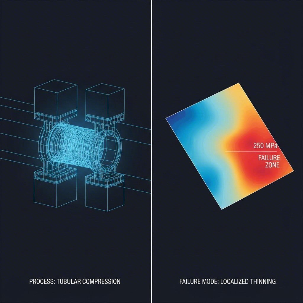
In the context of part fabrication, necking is a forming operation used to reduce the diameter of a cylindrical shell or tube at its open end. Unlike drawing, which displaces material to create depth, necking relies on compressive forces to shrink the circumference. This technique is ubiquitous in automotive manufacturing for components like catalytic converter shells, shock absorber tubes, and fuel filler necks.
Mechanics of the Necking Process
The operation forces a die over the end of a tubular blank. As the die advances, the material is subjected to compressive hoop stress, causing it to flow inward and thicken slightly. The success of the process depends on the material's ability to flow plastically in compression without collapsing.
There are two primary methods for achieving this reduction:
- Die Necking: A static die is pushed axially onto the tube. This is faster but limited by friction and the risk of buckling if the reduction ratio is too aggressive.
- Rotary or Spin Necking: The part or the tool rotates, applying localized pressure to gradually reduce the diameter. This method, often used for beverage cans and high-precision automotive parts, reduces friction and allows for greater diameter reductions without defects.
Common Defects in Necking Operations
Because the material is being compressed, the primary failure mode during the necking process is not splitting, but buckling or wrinkling. If the unsupported length of the tube is too long, or if the wall thickness is insufficient relative to the diameter, the metal will fold rather than flow. Engineers often use internal sleeves or staged reductions (multiple passes) to support the material and maintain geometric integrity.
For manufacturers dealing with complex geometries or high-volume production where precision is critical, partnering with specialized stamping services like Shaoyi Metal Technology can bridge the gap between rapid prototyping and mass production. Their expertise in IATF 16949-certified precision stamping ensures that even difficult forming operations like deep necking meet global OEM standards.
Necking as a Failure Mode: The Limit of Formability
In the broader context of Body-in-White (BIW) stamping, necking is the enemy. It defines the onset of material instability where deformation localizes into a narrow band, leading inevitably to fracture. Once a local neck forms, the material in that region thins rapidly while the surrounding material stops deforming entirely.
Diffuse vs. Local Necking
Understanding the progression of necking is vital for predicting failure in Advanced High-Strength Steels (AHSS):
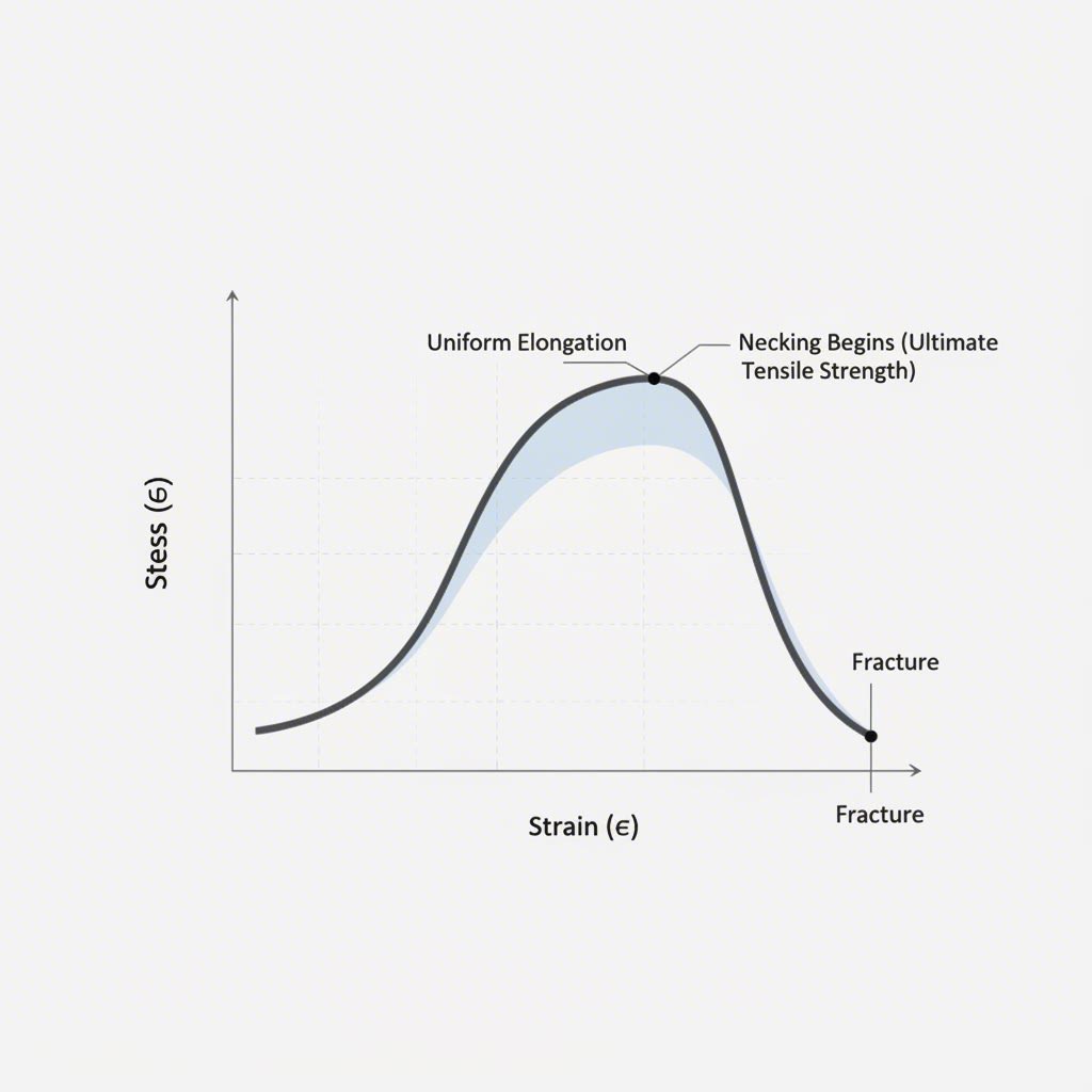
- Diffuse Necking: This is the initial stage where the width of the sheet begins to contract non-uniformly. It is spread over a larger area and does not immediately lead to failure. In tensile testing, this occurs at the Ultimate Tensile Strength (UTS) point.
- Local Necking: This is the critical failure limit. The deformation concentrates into a narrow band (roughly the thickness of the sheet). In this state, the material thins catastrophically with no further extension in the surrounding areas. In stamping simulation and design, the onset of local necking is considered the functional failure point of the part.
The Physics of Instability
Necking occurs when the material's work hardening rate can no longer compensate for the reduction in cross-sectional area. According to Considere's criterion, stability is maintained as long as the material strengthens (hardens) faster than it thins. When the work hardening rate drops below the true stress level, instability triggers.
This is why high n-value (strain hardening exponent) materials are preferred for complex stampings; they maintain their ability to distribute strain over a wider area for longer, delaying the onset of the neck.
Engineering Parameters & Material Behavior
Connecting the process and the failure mode requires a deep dive into material science. The behavior of steel during both the necking operation and necking instability is governed by its stress-strain curve.
The Role of the n-Value
The strain hardening exponent (n-value) is the most significant parameter:
- For Failure Prevention: A high n-value is desirable. It allows the material to stretch further before localized necking begins, which is crucial for deep-drawn body panels.
- For Necking Operations: Ironically, a very high n-value can sometimes be challenging for compressive necking operations if the material hardens too quickly, requiring higher forces and increasing the risk of buckling.
Forming Limit Curves (FLC)
To predict necking instability in production, engineers rely on the Forming Limit Curve (FLC). The FLC plots the major and minor strains at which local necking occurs. Any point on a stamped part that plots above this curve is expected to fail.
Modern detection methods, such as Digital Image Correlation (DIC), allow engineers to visualize strain accumulation in real-time. By tracking the surface pattern, DIC can identify the "necking band" before it becomes visible to the naked eye, enabling proactive die adjustments.

Defect Prevention & Process Control
Whether you are performing a necking operation or trying to prevent necking failure, control over friction and material flow is paramount.
Preventing Necking Instability (Sheet Metal)
- Lubrication Strategy: High friction restricts material flow, causing localized stretching. Improving lubrication in critical areas allows the material to draw in from adjacent zones, distributing the strain.
- Binder Force Adjustment: If the blank holder force is too high, the material cannot flow into the die, leading to excessive stretching and necking. Reducing this force allows more draw-in.
- Die Radii: Sharp radii concentrate stress. Increasing the die entry radius can reduce the peak strain and prevent the onset of a local neck.
Ensuring Successful Necking Operations (Tubular)
- Guide Sleeves: To prevent buckling during compressive necking, use external or internal guides to support the tube walls.
- Staged Reduction: Do not attempt a 50% diameter reduction in a single hit. Break the process into multiple steps (e.g., 20% -> 15% -> 10%) to manage the compressive stresses.
- Annealing: For aggressive reductions, intermediate annealing may be necessary to restore ductility and reduce the work-hardened state of the material.
Conclusion
Necking in automotive stamping is a duality that every process engineer must navigate. It is both a valuable forming technique for tubular components and a defining limit for sheet metal formability. By distinguishing between the compressive mechanics of the necking process and the tensile instability of necking failure, manufacturers can optimize their tooling designs and material selections. Success lies in balancing these forces—harnessing plastic deformation to shape the metal while respecting the physical limits where stability ends and failure begins.
Frequently Asked Questions
1. What is the difference between necking and drawing?
Drawing is a tensile process where a blank is pulled into a die to create depth, often reducing wall thickness. Necking (as a process) is a compressive operation applied to the open end of a tube to reduce its diameter. In drawing, material flows out of the flange; in necking, material is forced inward at the opening.
2. How does the n-value affect necking instability?
The n-value (work hardening exponent) indicates a material's ability to harden as it deforms. A higher n-value means the material resists localized thinning more effectively, distributing strain across a larger area. This directly delays the onset of necking instability, allowing for deeper and more complex stampings.
3. Can necking be detected before a fracture occurs?
Yes. While difficult to see with the naked eye until it is severe, localized necking can be detected using Digital Image Correlation (DIC) systems during testing. In production, a visible "groove" or line of thinning on the panel surface is a clear sign that the process is on the verge of splitting and requires immediate adjustment.