 Small batches, high standards. Our rapid prototyping service makes validation faster and easier —

Metal stamping die design guidelines: The Engineering Manual

TL;DR
Metal stamping die design guidelines are the engineering constraints that ensure parts are manufacturable, cost-effective, and dimensionally stable. The core "Golden Rule" is that most minimum feature sizes are dictated by the material thickness (MT); for example, the minimum hole diameter is typically 1.2x MT for ductile metals and 2x MT for stainless steel. Critical spacing rules require holes to be placed at least 2x MT from any edge to prevent bulging, while the minimum bend radius should generally equal 1x MT. Ultimately, successful die design balances these part geometry constraints with tooling mechanics—such as force distribution and strip stability—to guarantee repeatability in high-volume production.
Design for Manufacturability (DFM): Part Geometry Rules
Designing a stamped part requires strict adherence to mathematical constraints derived from the material's properties. Ignoring these guidelines often results in tool failure, excessive burrs, or deformed parts. The most effective designs treat the material thickness (MT) as the primary variable from which all other dimensions are calculated.
The Engineering Constraints Matrix
Use this reference table to validate your part geometry before finalizing the CAD model. These ratios are widely accepted industry standards for ensuring manufacturability.
| Feature | Standard Rule (Minimum) | Engineering Impact |
|---|---|---|
| Hole Diameter | 1.2x MT (Aluminum/Brass) 2x MT (Stainless Steel) |
Prevents punch breakage and excessive wear. |
| Slot Width | 1.5x MT | Reduces lateral force on the punch to avoid deflection. |
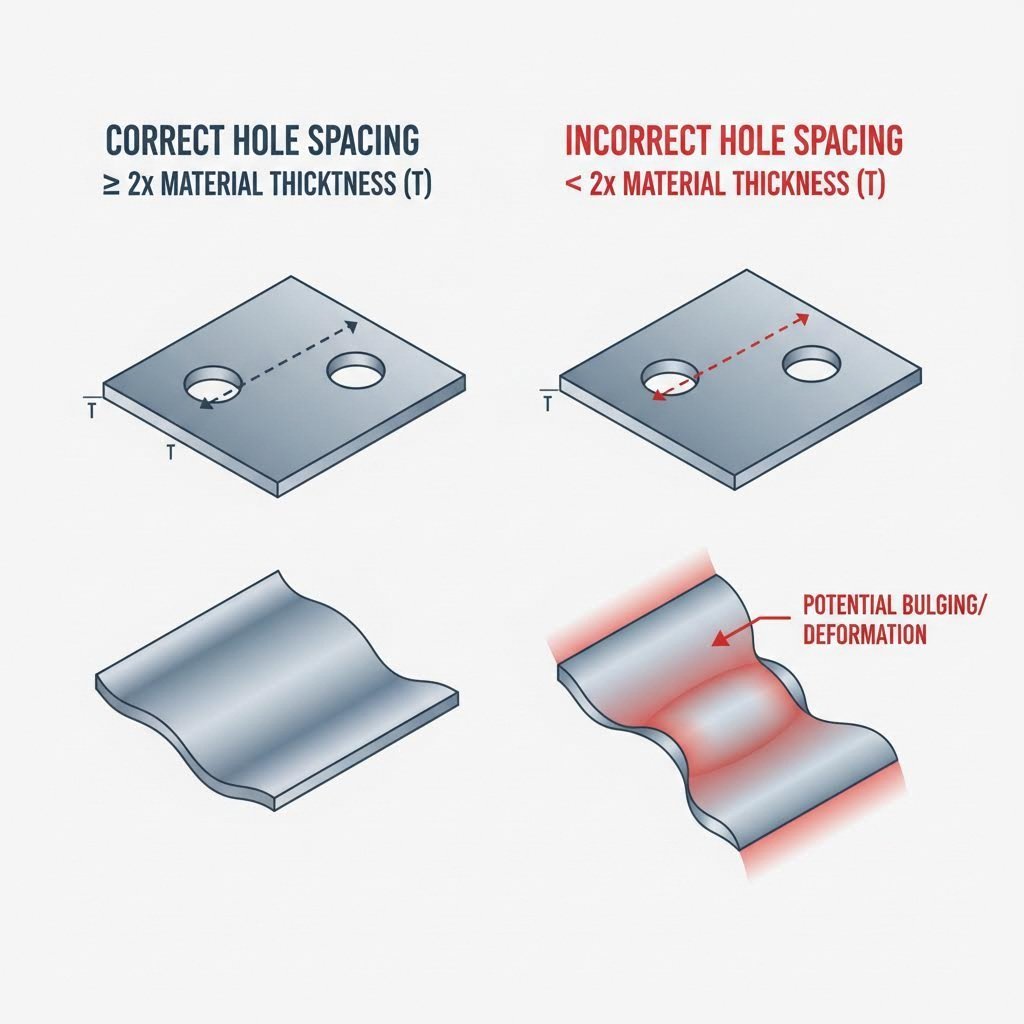
| Hole-to-Edge Distance | 2x MT | Prevents the web (material between hole and edge) from bulging outward. |
| Hole-to-Bend Distance | 2x MT + Bend Radius (Holes < 2.5mm) 2.5x MT + Bend Radius (Holes > 2.5mm) |
Ensures holes do not distort into ovals during the bending operation. |
| Bend Height | 2.5x MT + Bend Radius | Provides enough flat material for the die to grip and form the bend accurately. |
Holes, Slots, and Spacing
The integrity of a stamped part relies on maintaining sufficient material between features. According to Xometry's design standards, placing holes too close to an edge (less than 2x MT) causes the material to flow outward, creating a "bulge" that may require expensive secondary machining to remove. Similarly, slots require a width of at least 1.5x MT; anything narrower dramatically increases the risk of the punch snapping under the compressive load.
Bend Geometry and Grain Direction
Bending metal is not merely folding paper; it is a process of stretching and compressing specific grain structures. Keats Manufacturing emphasizes that bends should ideally be made perpendicular to the material's grain direction. Bending parallel to the grain often leads to cracking, especially in harder alloys like stainless steel or tempered aluminum. If your design requires a tight bend radius (approaching 1x MT), orienting the part layout on the strip to bend "across the grain" is critical for structural integrity.
Die Engineering & Construction: The 10 Laws of Performance
While DFM focuses on the part, the die itself must be engineered for stability, maintenance, and longevity. A well-designed die does not just produce parts; it protects the press and minimizes downtime.
Stability and Force Management
The most robust dies follow fundamental laws of physics and mechanics. One of the primary principles, often cited in The Fabricator's "10 Laws of Die Design", is to minimize strip lift. Excessive lifting of the strip between stations increases vibration and wear. Designers should stagger cutting punches and use appropriately sized lifters to keep the strip level and stable. Furthermore, balancing the forces under the press ram is non-negotiable. If heavy forming occurs on the right side of the tool, the design must include balancing forces (such as springs or dummy stations) on the left to prevent the ram from tipping, which destroys guide pins and bushings.
Maintenance-First Design
A die that is difficult to service is a poorly designed die. The principle of poka-yoke (mistake-proofing) should be applied to the tool assembly itself. Design cutting and forming sections so they cannot be installed backward or upside down. Clear service instructions should be etched or stamped directly onto the tool components, removing the need for "tribal knowledge" during maintenance.
Executing these sophisticated tooling strategies requires a manufacturing partner with deep engineering capabilities. For complex automotive or industrial components, working with a specialist like Shaoyi Metal Technology ensures that these rigorous design standards are met. Their IATF 16949 certification and capacity for 600-ton press operations allow them to bridge the gap between rapid prototyping and mass production, ensuring that even the most intricate die designs perform reliably over millions of cycles.
Material Selection & Tolerancing Standards
The interaction between the die material and the workpiece material defines the tool's lifespan and the part's accuracy. Selecting the right tool steel is a calculated decision based on production volume and workpiece hardness.
Tool Steel Selection
For high-volume production, Dramco Tool recommends using robust materials like D2 or A2 tool steel, which offer excellent wear resistance. In extreme cases, such as stamping abrasive stainless steel or high-strength alloys, carbide inserts may be necessary for cutting edges. While carbide is more expensive and brittle, it resists the abrasive wear that quickly dulls standard tool steels.
Understanding Tolerances
Engineers must set realistic expectations for stamped features. "Precision" in stamping is relative to the material thickness. For example, a standard tolerance for hole diameters might be +/- 0.002 inches, but this can vary based on the die clearance. A universal expectation is the presence of a burr on the cut edge. The industry standard acceptance criteria for burrs is typically 10% of the material thickness. If your design requires a burr-free edge, you must specify secondary deburring operations or specialized "shaving" stations within the progressive die.
Common Defects & Troubleshooting by Design
Many stamping defects can be predicted and prevented during the design phase. Addressing these potential failure modes early saves significant time and cost during production commissioning.
| Defect | Root Cause | Design Solution |
|---|---|---|
| Burrs | Excessive die clearance or dull tooling. | Set die clearance to 10-12% of MT; specify higher grade tool steel. |
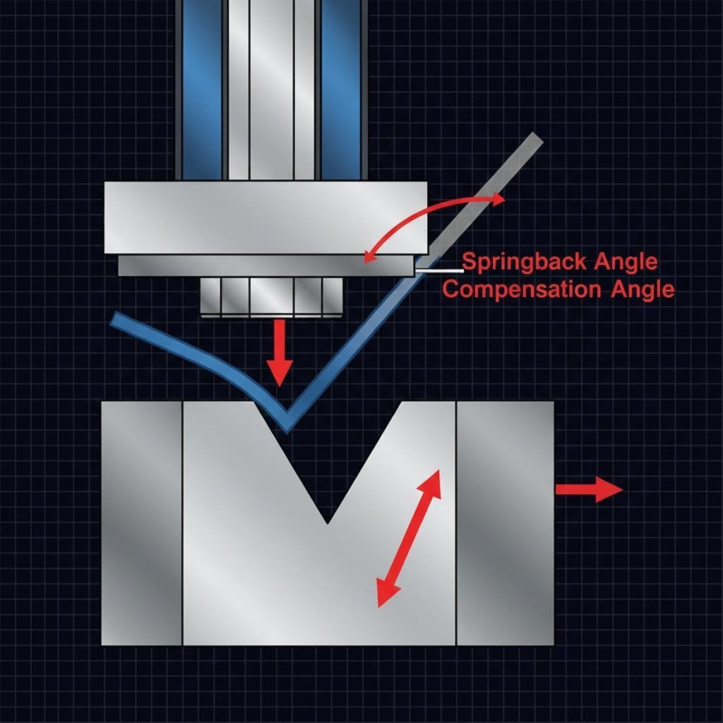
| Springback | Elastic recovery of metal after bending. | Overbend the feature by 1-2 degrees or use "coin" features at the bend radius to set the angle. |
| Tearing/Cracking | Bend radius too sharp or parallel to grain. | Increase bend radius to >1x MT; rotate part orientation to bend across the grain. |
| Deformation (Bulging) | Features too close to edge or bend. | Increase spacing to >2x MT or add relief notches to isolate the stress. |
Conclusion
Mastering metal stamping die design is a discipline of balancing constraints. It requires a deep understanding of how material thickness dictates geometry, how force distribution affects tool life, and how material properties influence final accuracy. By adhering to these engineering guidelines—respecting minimum ratios, designing for maintenance, and anticipating material behavior—engineers can create parts that are not only functional but also inherently manufacturable and cost-efficient at scale.