 Small batches, high standards. Our rapid prototyping service makes validation faster and easier —

Design for Manufacturability Metal Stamping: The Engineering Handbook

TL;DR
Design for Manufacturability (DFM) for metal stamping is the strategic engineering practice of optimizing part geometry to align with the physics of the stamping press and die capabilities. By designing parts that respect material constraints—rather than fighting them—engineers can reduce tooling costs by up to 50%, accelerate lead times, and eliminate common defects like cracking or springback.
The core of stamping DFM relies on adhering to proven "Golden Rules" of geometry. Key ratios include ensuring hole diameters are at least equal to material thickness (1T), maintaining a minimum bend radius of 1T to prevent fractures, and keeping features away from bend zones by a factor of 1.5T + Radius. Adopting these constraints early in the CAD phase is the most effective way to ensure production feasibility.
The Engineering Business Case: Why DFM Matters in Stamping
In metal stamping, the cost of a part is largely determined before the first sheet of metal is ever ordered. Approximately 70% of a product's final production cost is locked in during the design phase. "Over-the-wall" engineering—where designs are thrown to the manufacturer without prior consultation—often results in complex tooling requirements that drive up costs exponentially. A part designed without DFM might require a complex progressive die with 20 stations and expensive slide actions, whereas a DFM-optimized version could be produced with a simpler 12-station tool.
Collaborative DFM serves as a bridge between the ideal geometry and the harsh reality of cold-forming steel. It shifts the focus from "can this be made?" to "can this be made efficiently?" By engaging with a manufacturing partner early, engineers can identify cost drivers like tight tolerances that require precision grinding or features that necessitate secondary deburring operations. For example, relaxing a non-critical hole tolerance from ±0.002" to ±0.005" can significantly extend tool life and reduce piece-part price.
This is particularly critical when scaling from prototype to production. A design that works for laser cutting (low volume) often fails in a stamping press (high volume) due to different stress factors. Partners like Shaoyi Metal Technology specialize in bridging this gap, offering engineering support that ensures designs validated in the prototyping phase are robust enough for high-speed, high-volume stamping lines. Leveraging such expertise early prevents the costly "tooling redesign loop" that plagues many product launches.
Material Selection & Grain Direction Strategy
Material selection in stamping is a trade-off between function, formability, and cost. While functionality dictates the base alloy (e.g., Stainless Steel 304 for corrosion resistance or Aluminum 5052 for weight), the specific temper and grain direction dictate manufacturability. Harder materials offer greater yield strength but are more prone to cracking during complex forming operations.
The Critical Role of Grain Direction
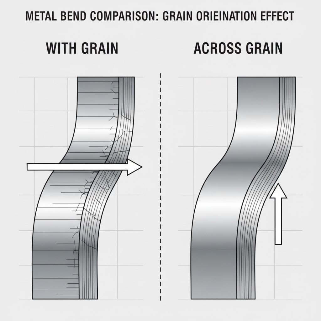
Sheet metal is produced by rolling, which elongates the metal's grain structure in the direction of the roll. This anisotropy means the material behaves differently depending on how it is formed relative to the grain:
- Bending Perpendicular (Across) the Grain: The strongest orientation. The material can withstand tighter radii without cracking because the grain structure is being folded rather than pulled apart.
- Bending Parallel (With) the Grain: The weakest orientation. The grains separate easily, leading to fractures on the outside radius, especially in harder alloys like 6061-T6 aluminum or high-carbon steel.
Engineers must specify grain direction on the print if tight bends are required. If part geometry demands bends in multiple directions, a 45-degree orientation relative to the grain is often used as a compromise to balance strength and formability across all features.
Critical Geometry Guidelines: Holes, Slots, and Webs
The physics of the punch-and-die interface imposes strict mathematical limits on cut features. Violating these ratios creates weak die sections that break prematurely, leading to downtime and maintenance costs. The table below summarizes the consensus "Rules of Thumb" for standard stamping operations.
| Feature | Minimum Ratio (Rule of Thumb) | Engineering Logic |
|---|---|---|
| Hole Diameter | ≥ 1.0T (Material Thickness) | Punches smaller than material thickness are prone to snapping under compressive load (buckling). |
| Web Width | ≥ 1.0T to 2.0T | Material between holes must be wide enough to maintain structural integrity and prevent distortion. |
| Hole-to-Edge | ≥ 2.0T | Prevents the edge from bulging outward or tearing when the punch strikes. |
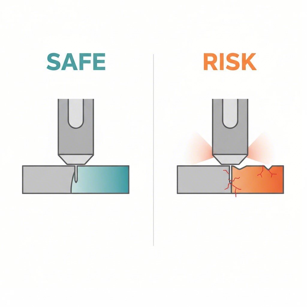
| Hole-to-Bend | ≥ 1.5T + Bend Radius | Stops the hole from deforming into an oval shape as material flows into the bend. |
Hole-to-Bend Proximity: One of the most common errors is placing a hole too close to a bend. As the metal stretches around the radius, any feature in the "deformation zone" will distort. If a design strictly requires a hole near a bend, the stamper must punch it after bending (adding a station/cost) or use a specialized relieving cut. A standard formula to ensure a hole remains round is to place its edge at least 1.5 times the material thickness plus the bend radius away from the bend tangent.
Bending and Forming Rules: Radii, Flanges, and Reliefs
Bending is not just folding; it is a controlled plastic deformation. To achieve consistent bends without failure, three parameters must be controlled: the Minimum Bend Radius, Flange Length, and Bend Relief.
Minimum Bend Radius
Sharp inside corners are the enemy of stamped parts. A radius of zero (sharp corner) creates a stress concentration point that inevitably leads to cracking. For most ductile metals like cold-rolled steel (CRS) or soft aluminum, the Minimum Inside Bend Radius should be ≥ 1T. Harder materials, such as stainless steel, often require ≥ 2T or greater. Designing with generous radii extends tool life and reduces the risk of part failure.
Minimum Flange Length
To bend a flange accurately, the material must stay in contact with the die throughout the forming process. If a flange is too short, it will slip into the V-die opening before the bend is complete, resulting in a distorted, non-parallel edge. A standard rule is that the Flange Length must be at least 3 to 4 times the material thickness. If a shorter flange is required, the stamper may need to form a longer flange and trim it in a subsequent operation, adding to the part cost.
Bend Reliefs
When a bend does not span the entire width of a part, the material at the ends of the bend line will tear unless a "Bend Relief" is added. A relief is a small rectangular or semi-circular notch cut into the base of the flange. This notch isolates the bent material from the unbent material, preventing tearing and deformation. The depth of the relief should typically exceed the bend radius + material thickness.
Tolerancing for Reality vs. Cost
Tolerance stringency is the single biggest driver of stamping die cost. While modern precision stamping can achieve tolerances as tight as ±0.001 inches, requiring this across the entire part is unnecessary and expensive. Tighter tolerances demand more precise die components (wire EDM cut), more frequent maintenance (sharpening), and slower press speeds.
- Block Tolerances: For non-critical features (e.g., clearance holes, air vents), rely on standard block tolerances (typically ±0.005" to ±0.010").
- Feature-to-Feature Dimensioning: Dimension critical features from each other rather than from the part edge. The edge is often produced by a trimming operation which inherently has more variability than a pierced hole. Dimensioning hole-to-hole keeps the tolerance chain tighter where it matters.
- Critical Features Only: Apply GD&T (Geometric Dimensioning and Tolerancing) only where absolutely necessary for assembly. If a flange angle tolerance is tightened from ±1° to ±0.5°, the stamper may need to add a re-strike station to the die to control springback, increasing the tooling investment.
Common Defects & Prevention (The DFM Checklist)
Engineers can anticipate and design out common failure modes by running a quick DFM checklist before finalizing the CAD model.
- Burrs: All stamped edges have burrs on the "break" side. Ensure your drawing specifies "Burr Direction" so that sharp edges are not on a user-handling surface. A standard allowable burr height is 10% of material thickness.
- Springback: Elastic recovery after bending causes the angle to open up. While the stamper compensates for this in the tool, using consistent material grades (e.g., specific high-strength low-alloy steel) helps maintain consistency. Avoid changing material suppliers mid-production to prevent variation.
- Oil Canning: Large, flat, unsupported areas of thin metal tend to buckle or "pop" like an oil can. Adding ribs, embossments, or steps stiffens the part without adding weight, preventing this defect.
Engineering for Efficiency
Mastering Design for Manufacturability in metal stamping is not about compromising the design intent; it is about refining it for reality. By respecting the physics of the stamping process—adhering to minimum ratios, choosing the right material grain strategy, and applying tolerances judiciously—engineers can drive down costs and ensure long-term production stability. A part optimized for the press is a part optimized for profit, quality, and speed.
Frequently Asked Questions
1. What is the minimum hole size for metal stamping?
As a general rule, the diameter of a punched hole should not be less than the material thickness (1T). For high-strength materials like stainless steel, a ratio of 1.5T or 2T is often recommended to prevent punch breakage. If smaller holes are required, they may need to be drilled or machined as a secondary operation.
2. How does material grain direction affect bending?
Metal grain direction is created during the rolling process of the sheet. Bending perpendicular to (across) the grain is stronger and allows for tighter radii without cracking. Bending parallel to the grain is weaker and more prone to fractures on the outside radius. Critical structural bends should always be oriented across the grain.
3. What is the difference between blanking and piercing?
Blanking is the operation of cutting the overall outer shape of the part from the metal strip; the piece removed is the useful part. Piercing (or punching) is the operation of cutting internal holes or shapes; the piece removed is scrap (slug). Both are cutting operations but serve different purposes in the die station sequence.