 Small batches, high standards. Our rapid prototyping service makes validation faster and easier —

Metal CNC Service Decoded: From Material Choice To Final Quote
What Metal CNC Service Actually Means for Your Projects
Ever wondered how complex metal components get manufactured with such remarkable precision? The answer lies in metal CNC service—a manufacturing approach that transforms digital designs into physical parts with accuracy measured in thousandths of an inch. Whether you're developing prototypes or scaling to production, understanding this technology helps you make smarter decisions about your projects.
CNC stands for Computer Numerical Control. In practical terms, this means a computer directs the movement of cutting tools along multiple axes using mathematical coordinates. Think of it as giving a machine extremely precise instructions: move exactly 2.375 inches left, then 1.500 inches forward, then cut 0.125 inches deep. The CNC machine follows these commands repeatedly without variation, creating identical parts whether you need one or one thousand.
From Digital Design to Physical Metal Parts
The journey from concept to finished component follows a clear path. You start with a 3D CAD model—your digital blueprint. This file then goes through CAM (Computer Aided Manufacturing) software, which calculates the exact toolpaths needed to carve your design from solid metal. The software generates G-code, a specialized language that tells the CNC machine precisely where to move, how fast to spin, and how deep to cut.
Once the code reaches the machine, raw metal stock gets secured to the worktable. The cutting process begins, with the machine removing material layer by layer until your part emerges. This subtractive approach differs fundamentally from 3D printing, which builds parts by adding material.
How Computer Control Transforms Raw Metal
Why does metal machining specifically demand this level of automation? Metal is unforgiving. Unlike wood or plastic, metals like steel and titanium require tremendous cutting forces and generate significant heat. Manual control simply cannot maintain the consistency needed for parts that must fit together perfectly or withstand demanding applications.
While manual machining requires one skilled technician per machine making real-time adjustments, a single trained CNC operator can oversee multiple machines simultaneously. The computer handles the precision—executing thousands of movements with identical accuracy—while humans focus on setup, quality verification, and problem-solving.
This shift from human-controlled to computer-controlled operations explains why modern manufacturing achieves tolerances as tight as ±0.001 inch. A CNC cutting machine executes programmed instructions without fatigue, distraction, or the micro-variations inherent in manual work.
The Technology Behind Precision Metal Components
Metal CNC services encompass several distinct processes, each suited to different part geometries:
- Milling: Rotating cutting tools remove material from stationary workpieces, ideal for flat surfaces, pockets, and complex 3D contours
- Turning: The workpiece rotates while stationary tools shape it, perfect for cylindrical components like shafts and bushings
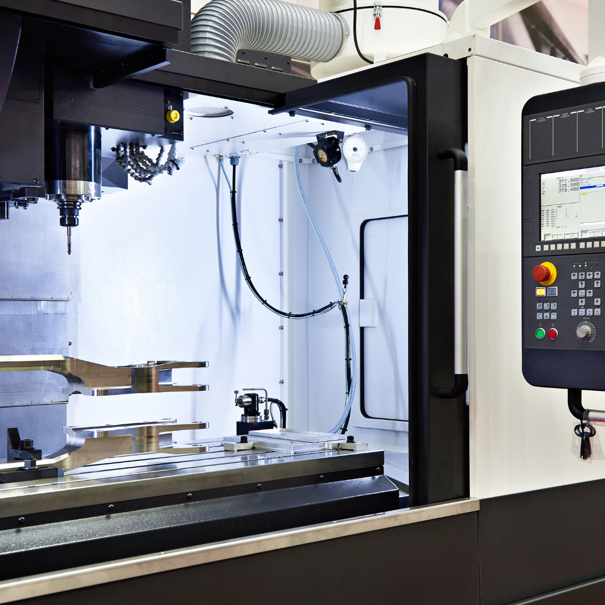
- Multi-axis operations: Advanced machines move on 4 or 5 axes simultaneously, enabling complex geometries in single setups
Each CNC machine operates along defined axes. The X-axis moves side to side, the Y-axis moves front to back, and the Z-axis moves up and down. When you combine metal and CNC technology, you gain the ability to produce everything from simple brackets to intricate aerospace components with repeatable precision.
Understanding these fundamentals positions you to communicate effectively with service providers, specify appropriate tolerances, and ultimately get better results from your metal cnc projects. The sections ahead will explore each process type, material selection, and cost factors in detail—building on this foundation to help you navigate every decision from design to final quote.
Understanding CNC Milling Turning and Multi-Axis Operations
Now that you understand what metal CNC service involves, let's break down the actual machining processes you'll encounter. When requesting quotes or discussing projects with manufacturers, knowing the difference between milling, turning, and multi-axis operations helps you communicate your needs clearly—and understand why certain parts cost more than others.
Milling Operations and Axis Capabilities Explained
CNC machining milling is the most versatile process in the metal fabrication toolkit. During milling, spinning cutting tools remove material from a stationary workpiece. Picture a drill bit moving not just up and down, but also side to side and front to back, carving away metal to reveal your part's geometry.
The complexity of shapes you can achieve depends entirely on how many axes your machine controls. Here's where it gets interesting:
3-Axis Milling operates along X, Y, and Z linear directions. The workpiece stays fixed while the spindle moves in three straight-line paths. This setup handles flat surfaces, pockets, and drilled holes exceptionally well. However, you can only machine one face at a time. Need features on multiple sides? That requires stopping the machine, repositioning the part in a new fixture, and starting again. Each setup adds time and introduces potential alignment errors.
4-Axis Milling adds rotation around the X-axis (called the A-axis). Your workpiece can now spin while being cut, enabling access to four sides in a single setup. According to CloudNC's machining analysis, a part requiring two unique fixtures on a 3-axis machine often needs only one fixture on a 4-axis machine—eliminating setup costs and reducing human error risks. This capability proves valuable for machining complex profiles like cam blades and helical features.
5-Axis Milling represents the pinnacle of precision CNC machining. These machines utilize two rotational axes (typically A and C, or B and C) alongside the three linear movements. The result? Your cutting tool can approach the workpiece from virtually any angle. Those 5 axis cnc machining services enable compound angle features—surfaces angled in two directions simultaneously—that simply cannot exist on simpler machines.
Consider an aerospace bracket with angled mounting holes, curved surfaces, and undercuts. On a 3-axis machine, you might need five or six setups, each introducing tolerance stack-up. On a 5-axis machine, you complete it in one setup with superior accuracy between all features.
CNC Turning for Rotational Components
While milling excels at prismatic shapes, CNC turning dominates when you need cylindrical parts. Shafts, bushings, pulleys, and threaded fasteners all start on a lathe.
The fundamental difference? In turning, your workpiece spins while stationary tools cut into it. The machine controls only X (position along the part) and Z (distance from the center of rotation). Since the spinning creates your circular geometry automatically, there's no need for Y-axis control.
CNC turned parts achieve remarkable concentricity—the property of having all circular features share a common center axis. This matters tremendously for rotating assemblies where even slight imbalance causes vibration and premature wear.
The CNC cutting precision becomes especially critical when machining threads. External and internal threads require exact timing between the spindle rotation and tool movement. Get the coordination wrong by even milliseconds, and your threads won't engage properly with mating components.
When Multi-Axis Machining Becomes Essential
Sounds complex? It doesn't need to be. The decision between 3-axis, 4-axis, and 5-axis machining often comes down to three practical questions:
- Does your part have features at angles to the main faces? If yes, multi-axis capability eliminates the need for angled fixtures or multiple setups.
- Do features on different faces need tight positional relationships? Single-setup machining maintains better tolerances between features than repositioning between setups.
- Does your geometry include compound curves or sculptured surfaces? 5-axis continuous machining can follow complex 3D contours that indexed operations cannot achieve.
Beyond axis count, specialized processes handle unique challenges. EDM (electrical discharge machining) uses electrodes to slowly erode material with electrical sparks—achieving ultra-precision fits where conventional CNC cutting cannot reach. As noted in Fictiv's manufacturing guide, EDM produces fits so precise that puzzle-piece assemblies show virtually invisible seams.
| Process Type | Best Applications | Complexity Level | Typical Part Examples |
|---|---|---|---|
| 3-Axis Milling | Flat surfaces, pockets, drilled/tapped holes | Standard | Brackets, plates, enclosure panels |
| 4-Axis Milling | Multi-sided features, helical patterns | Moderate | Cam profiles, impellers, gear blanks |
| 5-Axis Milling | Compound angles, sculptured surfaces | Advanced | Turbine blades, aerospace fittings, medical implants |
| CNC Turning | Cylindrical parts, concentricity-critical components | Standard to Moderate | Shafts, bushings, threaded fasteners, rollers |
| EDM | Ultra-precision fits, hard materials, complex internal shapes | Specialized | Die components, injection mold cavities, micro-features |
The beauty of modern CNC fabrication lies in combining these processes. A complex component might start on a lathe for its cylindrical base, move to a 5-axis mill for angled features, then receive EDM finishing for critical mating surfaces. Understanding which process handles which geometry helps you design more manufacturable parts—and anticipate costs before you request quotes.
With process capabilities clear, the next crucial decision involves material selection. Different metals machine very differently, and your choice directly impacts both cost and performance.
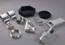
Metal Material Selection Guide for CNC Machining
Choosing the right material might be the most consequential decision you make before submitting a quote request. Your material selection directly affects machining time, tool wear, surface finish quality, and ultimately your per-part cost. Beyond economics, material properties determine whether your finished component survives its intended application—or fails prematurely.
Let's walk through the most commonly machined metals and when each makes sense for your project.
Aluminum Alloys for Lightweight Precision
When machinability matters most, aluminum machining delivers exceptional results. Aluminum cuts faster than steel, produces excellent surface finishes, and extends tool life significantly. These factors translate directly into lower costs per part.
But not all aluminum alloys behave identically. According to Xometry's material selection guide, the 2000-series alloys (like 2011) contain copper for improved machining speeds and are ideal for threading operations. However, that same copper content reduces weldability and corrosion resistance—important trade-offs to consider.
For structural applications requiring both strength and corrosion resistance, the 6000-series alloys shine. Alloy 6082 offers tensile strength around 180 MPa with excellent weldability, making it suitable for aerospace components and highly loaded structures. Meanwhile, 7000-series alloys like 7075 deliver the highest strength (approximately 570 MPa tensile) and outstanding fatigue resistance—explaining their extensive use in aircraft structural parts.
The takeaway? Match your aluminum grade to your application requirements, not just your machining budget.
Steel Selection from Mild to Tool-Grade
Steel remains the workhorse material for demanding applications. The challenge lies in navigating the dozens of available grades, each optimized for different performance characteristics.
Mild structural steels like 1.0038 (equivalent to Fe360B) offer good plasticity, toughness, and weldability at economical prices. With yield strength around 235 MPa, these materials form the backbone of construction and general fabrication.
Medium carbon steels such as 1.0503 step up significantly in strength (630 MPa tensile) and wear resistance. These grades machine into screws, forgings, shafts, and precision components where dimensional accuracy matters in high-speed applications.
Alloy steels like 1.7225 (42CrMo4) add chromium and molybdenum for enhanced hardenability and impact resistance. Machine builders rely on this material for axles, gear shafts, and large plastic mold bases.
Stainless steel introduces an entirely different calculus. The chromium content (minimum 10.5%) creates a self-healing oxide layer that resists corrosion beautifully—but also makes machining more challenging. Grade 1.4301 (304 stainless) handles kitchen equipment, sinks, and general corrosion-resistant applications. For environments involving chlorides or non-oxidizing acids, grade 1.4404 (316L) adds molybdenum for enhanced protection. Marine applications often specify 1.4571, which incorporates titanium for structural stability at temperatures exceeding 800°C.
When Titanium and Specialty Metals Make Sense
Titanium commands premium pricing for good reason. Its exceptional strength-to-weight ratio—approximately 60% of steel's density with comparable strength—makes it irreplaceable in aerospace, medical, and high-performance applications.
Grade 2 titanium (commercially pure) offers outstanding corrosion resistance and biocompatibility, explaining its dominance in medical implants. Grade 5 (Ti-6Al-4V) adds aluminum and vanadium for even greater strength while maintaining corrosion resistance in demanding environments including seawater. According to Xometry's specifications, this alloy withstands a wide range of adverse environmental factors, making it ideal for subsea oil and gas structures.
Beyond titanium, specialty applications call for other metals:
- Copper alloys: Electrolytic copper (2.0060) delivers high electrical conductivity for busbars, motors, and windings. Machining bronze produces components requiring both wear resistance and aesthetics—bronze CNC parts appear in artistic fixtures, marine hardware, and precision bearings.
- Brass: Free-machining brass (2.0401) offers exceptional hot formability and solderability, serving the sanitary industry and automotive sector extensively.
- Zinc alloy metal: When die-casting provides a more economical production route for complex geometries, zinc alloys deliver excellent dimensional stability and surface finish. CNC machining then refines cast zinc blanks to final specifications.
| Material | Key Properties | Machinability Rating | Common Applications | Relative Cost |
|---|---|---|---|---|
| Aluminum 6082 | High strength, good weldability, corrosion resistant | Excellent | Aerospace parts, structural components, rail coaches | € |
| Aluminum 7075 | Highest strength, fatigue resistant, tough | Very Good | Aircraft structures, high-stress components | € |
| Steel 1.0503 (C45) | High tensile strength (630 MPa), wear resistant | Good | Shafts, screws, forgings, precision parts | €€ |
| Stainless 1.4301 (304) | Excellent corrosion resistance, formable | Moderate | Kitchen equipment, tubes, sinks, springs | €€€ |
| Stainless 1.4404 (316L) | Superior chemical resistance, heat stable | Moderate | Food processing, marine fittings, fasteners | €€€ |
| Titanium Grade 2 | Biocompatible, corrosion resistant, low thermal expansion | Challenging | Medical implants, weight-critical structures | €€€€€ |
| Titanium Grade 5 | Exceptional strength, seawater resistant | Challenging | Aerospace, subsea equipment, high-performance parts | €€€€€ |
| Copper 2.0060 | High electrical/thermal conductivity, formable | Excellent | Electrical components, busbars, motor windings | €€€ |
| Brass 2.0401 | Free-cutting, solderable, aesthetically pleasing | Excellent | Sanitary fittings, decorative hardware, connectors | €€ |
Engineering Plastics Machined Alongside Metals
While exploring material options, you'll likely encounter terms like delrin and acetal. What is delrin exactly? It's a brand name for polyoxymethylene (POM), an engineering thermoplastic with exceptional dimensional stability and machinability. What is acetal? It's the generic name for the same polymer family—delrin plastic is simply DuPont's trademarked version.
These materials matter because many metal CNC service providers machine plastics using identical equipment. When your assembly requires both metal structural components and plastic wear surfaces, working with a single supplier simplifies logistics. POM (delrin) excels in wet environments with zero porosity, making it ideal for bushings, gears, and electrical components. Other machinable plastics include PEEK for high-temperature applications and polycarbonate for transparent protective covers.
With your material selection narrowed down, the next critical factor to understand is tolerance specifications—the precision standards that define whether your parts will function as designed.
Tolerances and Precision Standards Explained Simply
You've selected your material and understand the machining processes available. Now comes a specification that directly impacts both cost and functionality: tolerances. These seemingly small numbers—often expressed as ±0.005" or ±0.001"—determine whether your machined parts fit together perfectly or become expensive paperweights.
But what do these measurements actually mean in practical terms? And how do you know which tolerance level your project genuinely requires?
Standard vs Precision Tolerance Requirements
Imagine you're machining a shaft that needs to slide into a bearing housing. If the shaft comes out even slightly oversized, it won't fit. Too undersized, and it wobbles—creating vibration and premature wear. Tolerances define the acceptable range between "fits perfectly" and "rejected."
According to American Micro Industries' machining tolerance guide, CNC machining typically achieves tolerances of ±0.005" (0.127 mm) as a standard benchmark. This means a part dimensioned at 2.000" might measure anywhere from 1.995" to 2.005" and still pass quality inspection.
Here's how tolerance tiers break down in practice:
- Standard Tolerance (±0.005"): Suitable for most general-purpose applications where parts don't require precise fits. Brackets, enclosures, and non-mating surfaces typically fall here. This tier offers the most economical production.
- Precision Tolerance (±0.001"): Required when parts must fit together with minimal clearance or interference. Bearing housings, shaft fits, and assembly interfaces often demand this level. Expect increased machining time and quality checks.
- High-Precision Tolerance (±0.0005" or tighter): Reserved for aerospace components, medical devices, and precision instruments. These specifications require specialized equipment, climate-controlled environments, and extensive inspection protocols.
The relationship between decimal places and manufacturing difficulty is direct. As noted by 3ERP's tolerance analysis, a tolerance of ±0.02" permits a range ten times wider than ±0.002"—significantly affecting production complexity and cost.
What Tolerance Specifications Mean for Part Function
Consider a practical scenario: you're designing machining parts for a pneumatic cylinder assembly. The piston must seal against the cylinder wall while still moving freely. Specify tolerances too loose, and air leaks past the seal. Too tight, and the piston binds.
For CNC machining parts involving threads, precision becomes even more critical. What is the tolerance for thread holes in typical applications? Thread tolerances follow specific standards like ISO 965-1 for metric threads. A standard 3/8 NPT thread dimensions specification requires precise control of both major and minor diameters, plus the thread pitch and angle.
Similarly, when drilling for pipe threads like 1 4 npt hole size specifications, the drilled hole diameter must match tapping requirements exactly. The pilot hole for 1/4" NPT typically requires a 7/16" drill (0.4375"), with tolerance tight enough to ensure proper thread engagement without excessive material removal during tapping.
Beyond threads, tolerance decisions cascade through your entire design:
- Mating surfaces: Parts that press-fit or slip-fit together need coordinated tolerances on both components
- Assembly stack-up: When multiple parts combine, individual tolerances accumulate—four parts with ±0.005" tolerance could result in ±0.020" total variation
- Functional clearances: Moving parts need controlled gaps for lubrication and thermal expansion
Matching Precision Levels to Application Needs
Here's where many engineers over-specify—requesting ±0.001" tolerances across entire drawings when only critical features require such precision. This approach dramatically inflates costs without improving function.
Why do tighter tolerances cost more? The answer involves multiple factors:
- Slower machining speeds: Achieving finer finishes and tighter dimensions requires reduced feed rates and spindle speeds
- Specialized equipment: High-precision work often demands temperature-controlled facilities and premium machine tools
- Extended inspection time: Complex measuring equipment like CMMs (Coordinate Measuring Machines) must verify each critical dimension
- Higher rejection rates: Parts falling outside narrow tolerance bands become scrap, increasing effective unit costs
The smart approach? Apply tight tolerances only where function demands them. A structural bracket might need ±0.001" on its mounting hole positions while accepting ±0.010" on its overall outline dimensions. This selective specification—called geometric dimensioning and tolerancing (GD&T)—optimizes both cost and performance.
International standards like ISO 2768 provide general tolerance classes (fine, medium, coarse, very coarse) that manufacturers recognize universally. Specifying "ISO 2768-m" on non-critical dimensions tells your machining partner to apply medium-class general tolerances, eliminating the need to tolerance every single feature individually.
Understanding tolerances helps you communicate effectively with precision machining services—specifying exactly what you need without paying for precision you won't use. With dimensional requirements clear, the next consideration involves surface finishes: the final appearance and protective treatments that prepare your parts for their intended environment.
Surface Finishing Options and When to Use Each
Your machined part emerges from the CNC process with precise dimensions and clean geometry—but it's not ready for service yet. Raw machined surfaces show tool marks, may lack corrosion protection, and rarely match the aesthetic requirements of finished products. That's where surface finishes enter the picture, transforming functional metal into protected, visually appropriate components.
Choosing the right finish depends on three questions: What environment will your part face? What level of protection does it need? And what should it look like? Let's break down the options that matter most for metal CNC projects.
Anodizing and Coating Options for Aluminum Parts
When working with aluminum, anodizing delivers protection that paint simply cannot match. Unlike coatings that sit on top of metal, anodizing transforms the surface itself through electrochemical oxidation. The result? According to Sinorise's surface treatment analysis, anodizing creates a bond 5 to 10 times stronger than conventional paint adhesion.
Here's how it works: your aluminum part gets submerged in an acidic electrolyte bath while electrical current passes through. This controlled process grows aluminum oxide (Al2O3) directly from the base material, creating a hard, integral layer that won't chip or peel.
You'll encounter three anodizing types:
- Type I (Chromic Acid): Produces the thinnest coating, ideal for aerospace applications where fatigue resistance matters
- Type II (Sulfuric Acid): The most common choice, offering good corrosion protection with excellent dye absorption for colored finishes
- Type III (Hardcoat): Creates a thick, extremely hard surface reaching 60-70 HRC—comparable to tool steel—for severe wear applications
The porous structure of anodized surfaces absorbs dyes beautifully, allowing manufacturers to add lasting colors from bronze to black to vibrant blues and reds. Research indicates these finishes maintain approximately 95% of their original brightness even after twenty years of outdoor exposure.
For cost-effective corrosion protection without the durability requirements, powder coating works across aluminum, steel, and stainless steel. Dry polymer particles—typically polyester or epoxy—get sprayed electrostatically onto grounded metal parts. The coating then cures at 180-200°C, melting into a smooth, solvent-free film ranging from 50 to 300 micrometers thick. Beyond metals, similar powder coating techniques apply to CNC polycarbonate enclosures when chemical resistance matters more than optical clarity.
Powder coating's environmental advantage deserves mention: virtually no volatile organic compounds (VOCs) escape during application, and manufacturers recycle up to 98% of overspray. The trade-off? Thick coatings may obscure fine details on precision machined features.
Plating and Passivation for Corrosion Protection
When your parts must resist harsh environments or conduct electricity reliably, metal plating provides targeted solutions that anodizing cannot.
Electroless nickel plating deposits a nickel-phosphorus alloy through chemical reduction rather than electrical current. This approach creates remarkably uniform coatings—within ±2 microns—even on complex geometries like internal threads. Higher phosphorus content improves corrosion resistance while lower phosphorus increases hardness to approximately 60 HRC. Aluminum, steel, and stainless steel all accept electroless nickel readily.
Zinc plating (galvanization) protects steel through a clever mechanism: zinc corrodes preferentially. When the coating gets scratched, exposing base steel, the zinc sacrifices itself first—continuing to protect the underlying metal. Salt spray testing confirms zinc-nickel alloys withstand around 1,000 hours of exposure, making them standard for automotive fasteners and structural hardware.
Chrome plating delivers that mirror-bright finish you see on bathroom fixtures and automotive trim. Beyond aesthetics, chrome provides excellent wear resistance for moving parts. Modern trivalent chromium processes have reduced toxicity by approximately 90% compared to traditional hexavalent methods.
For stainless steel parts, passivation represents the essential finishing step. This chemical treatment removes free iron from the surface without adding any coating thickness. The result is enhanced corrosion resistance with a smooth, shiny appearance—and no masking required for threaded holes or tight-tolerance features. Similar non-dimensional treatments work well on acetal plastic components that machine alongside metal parts in mixed assemblies.
Black oxide provides a cost-effective matte finish for ferrous metals. The high-temperature chemical bath creates magnetite (Fe3O4), offering mild corrosion resistance when sealed with oil. It's popular for tools, firearms, and machinery where the dark appearance reduces glare without adding dimensional thickness.
Choosing Finishes Based on End-Use Environment
Surface finish selection ultimately traces back to what your part will experience in service. Consider these environmental factors:
- Outdoor exposure: UV radiation, rain, and temperature cycling demand finishes like powder coating (15-20 year color retention) or Type II anodizing
- Chemical contact: Acids, alkalis, and solvents require electroless nickel or specific anodizing types matched to the chemical environment
- Wear conditions: Sliding contact or abrasive environments call for Type III hardcoat anodizing or hard chrome plating
- Electrical requirements: Anodizing and powder coating insulate; chrome and nickel plating preserve conductivity
- Aesthetic goals: Powder coating offers thousands of RAL colors; anodizing provides metallic sheens; media blasting creates uniform matte textures
Speaking of media blasting—this abrasive process deserves mention as both a standalone finish and a preparation step. Pressurized jets of glass beads, aluminum oxide, or plastic media create uniform matte surfaces while removing machining marks. According to Fictiv's finishing guide, combining media blasting with anodizing produces the sophisticated surface finish found on premium consumer electronics.
| Finish Type | Compatible Metals | Protection Level | Aesthetic Result | Best Applications |
|---|---|---|---|---|
| Type II Anodizing | Aluminum | Excellent corrosion resistance; 1,000+ hours salt spray | Metallic sheen; dyeable to multiple colors | Consumer electronics, architectural components, aerospace |
| Type III Hardcoat Anodizing | Aluminum | Superior wear resistance; 60-70 HRC hardness | Dark gray to black; matte | Sliding components, valve bodies, military equipment |
| Powder Coating | Aluminum, Steel, Stainless Steel | Good corrosion and UV protection; impact resistant | Thousands of colors; gloss, matte, or textured | Outdoor furniture, appliances, automotive parts |
| Electroless Nickel | Aluminum, Steel, Stainless Steel | Excellent chemical resistance; uniform coverage | Metallic gray; semi-bright | Hydraulic cylinders, electronic housings, food processing |
| Zinc Plating | Steel | Good sacrificial protection; 500-1,000 hours salt spray | Silver or yellow chromate conversion | Fasteners, brackets, automotive hardware |
| Passivation | Stainless Steel | Enhanced inherent corrosion resistance | Clean, bright; no color change | Medical devices, food equipment, marine hardware |
| Black Oxide | Steel, Stainless Steel | Mild corrosion resistance (with oil seal) | Matte black; non-reflective | Tools, firearms, machine components |
| Media Blasting | All metals including brass and bronze | Preparation step; improves coating adhesion | Uniform matte; hides machining marks | Pre-anodizing prep, cosmetic improvement, paint preparation |
One critical note: many finishes add dimensional thickness that can interfere with tight tolerances and threaded features. Masking—using rubber plugs or protective lacquers—shields critical surfaces during finishing but adds time and cost. Design your parts with finishing in mind, accounting for coating thickness on mating surfaces.
With material, tolerance, and finishing specifications defined, you're ready to tackle the question everyone wants answered: what will this actually cost? The next section breaks down the factors that drive metal CNC service pricing.
Understanding Metal CNC Pricing and Cost Factors
You've specified your material, defined your tolerances, and selected appropriate finishes. Now comes the question that drives every project decision: what will this actually cost? Unlike commodity products with fixed price tags, metal CNC service pricing varies dramatically based on factors specific to your project. Understanding these cost drivers helps you make informed design choices—and avoid sticker shock when quotes arrive.
The challenge? Most machine shops provide a single quoted price without breaking down how they calculated that number. Let's pull back the curtain on what actually influences your per-part costs.
What Actually Drives Metal CNC Service Costs
According to Scan2CAD's machining economics analysis, machining time represents the most significant cost driver—often outweighing setup costs, material costs, and finishing operations combined. Every minute your part spends on a CNC machine accumulates charges for equipment, energy, and operator time.
Here's how the primary cost factors break down:
Material selection and raw material costs: As noted by Rapid Axis's pricing guide, exotic materials like Inconel or titanium can cost orders of magnitude more than aluminum or stainless steel. Beyond the raw stock price, harder materials require slower cutting speeds, specialized tooling, and more frequent tool changes—all adding to machinist metal cost calculations.
Part complexity and machining time: The more features your design contains, the longer machining takes. Deep pockets require multiple passes. Complex contours demand slower feed rates. Features on multiple faces may require repositioning between operations. Each added minute translates directly into higher CNC machining price per unit.
Tolerance requirements: Tighter tolerances mean slower machining speeds, more inspection steps, and higher rejection rates. A part requiring ±0.001" precision might cost significantly more than an identical geometry specified at ±0.005"—not because of material differences, but because of the additional care needed during production.
Finishing requirements: Anodizing, plating, powder coating, and other surface treatments add post-machining operations. Each finishing step requires handling, processing time, and often transport to specialized facilities. According to MakerVerse's cost reduction guide, secondary operations like deburring, inspection, plating, and heat treating can sometimes exceed the main manufacturing cost.
How Volume Affects Per-Part Pricing
Here's where understanding manufacturing economics pays dividends: setup time distribution dramatically changes your per-unit cost as quantities increase.
Every CNC machining project involves upfront preparation—programming toolpaths, setting up fixtures, loading material, and dialing in cutting parameters. For a custom machine setup on a complex part, this preparation might take several hours. On a single prototype, you absorb that entire setup cost on one unit. Spread across a thousand production parts, the same setup cost becomes negligible per piece.
This explains why single prototypes cost significantly more per unit than production runs. It's not that machine shops overcharge for prototypes—the fixed costs simply have nowhere else to go. As Rapid Axis notes, when ordering larger quantities, the programming happens only once while benefiting every subsequent part.
Material purchasing compounds this effect. Buying aluminum bar stock for ten parts costs more per pound than ordering enough for five hundred. Local machine shops often stock common materials, but specialty alloys may require minimum order quantities regardless of how many parts you actually need.
The practical implication? When requesting a CNC quote online, always ask for pricing at multiple quantities. You might discover that doubling your order reduces per-part cost by 30%—making it economical to build inventory rather than reordering frequently.
Design Decisions That Impact Your Budget
The good news? Many cost factors remain within your control during the design phase. Before submitting your next request for online machining quotes, consider these strategies that reduce CNC machining costs without compromising functionality:
- Simplify geometries where possible: Eliminate features that don't serve functional purposes. Every pocket, hole, and contour adds machining time. If a decorative chamfer doesn't improve your product, consider removing it.
- Select appropriate tolerances—not excessive ones: Apply tight tolerances only where function demands them. Specifying ±0.001" across an entire drawing when only mounting holes require precision multiplies costs unnecessarily.
- Choose readily available materials: Common alloys like 6061 aluminum and 304 stainless steel cost less and ship faster than exotic grades. Match material properties to actual requirements rather than over-specifying.
- Design for standard tooling: Internal corner radii matching common end mill sizes, hole diameters aligning with standard drill sizes, and thread specifications using stock taps all reduce tool changes and setup time.
- Minimize setups: Features accessible from fewer orientations require fewer fixture changes. Parts machined complete in one or two setups cost less than those needing four or five repositionings.
- Consider near-net-shape blanks: Starting from cast or extruded stock closer to final dimensions reduces material removal time compared to machining from solid rectangular blocks.
MakerVerse's analysis confirms that design optimization represents the highest-impact opportunity for cost reduction. Removing unnecessary features, using standard tool sizes, and selecting cost-effective manufacturing methods often matter more than negotiating shop rates.
One final consideration: prototype-to-production transition. Your initial prototypes will carry premium pricing due to setup amortization. But those same prototypes offer opportunities to refine your design for manufacturing. Working with your machining partner to identify cost-saving modifications before committing to production quantities often yields substantial savings that justify the higher per-unit prototype investment.
With cost factors clearly understood, the next critical evaluation involves quality assurance—specifically, the certifications and standards that separate capable manufacturers from those who merely claim precision capabilities.
Industry Certifications and Quality Standards Decoded
You've evaluated materials, tolerances, finishes, and cost factors. But here's a question that separates reliable metal CNC service providers from risky ones: what certifications do they hold? Those acronyms on a manufacturer's website—ISO 9001, AS9100, IATF 16949—aren't just marketing badges. They represent documented proof that a facility follows rigorous quality management practices verified by independent auditors.
Yet most manufacturers list certifications without explaining what they actually guarantee. Let's decode these standards so you can evaluate suppliers with confidence.
Quality Certifications and What They Guarantee
At the foundation of manufacturing quality sits ISO 9001—the internationally recognized standard for quality management systems. According to Hartford Technologies' certification guide, this certification confirms that an organization's products or services comply with customer expectations and regulatory mandates.
What does ISO 9001 certification actually require? Facilities must implement documented procedures for every aspect of production, from incoming material inspection through final shipment. Regular internal audits verify compliance. Management reviews ensure continuous improvement. Customer feedback gets systematically analyzed and addressed.
Think of ISO 9001 as the baseline—any precision machining companies worth considering should hold this certification at minimum. But industry-specific applications demand additional standards that address unique risks and requirements.
Industry-Specific Standards from Automotive to Aerospace
Different industries face different challenges. A bracket for consumer electronics doesn't carry the same consequences of failure as an aerospace structural component or a medical implant. Specialized certifications address these elevated requirements:
- IATF 16949 (Automotive): Developed by the International Automotive Task Force, this standard builds upon ISO 9001 with additional requirements for product design, production processes, and customer-specific standards. Automotive applications demand IATF 16949 compliance because vehicle safety depends on consistent, defect-free components. The certification mandates Statistical Process Control (SPC)—using data-driven methods to monitor and control manufacturing variation in real-time.
- AS9100D (Aerospace): As noted in 3ERP's certification analysis, this standard emphasizes rigorous risk management, configuration control, and product traceability. Every aerospace component must be traceable from raw material source through final inspection. The consequences of failure at 35,000 feet demand nothing less.
- ISO 13485 (Medical Devices): Patient safety drives this certification. According to American Micro Industries' certification guide, the standard specifically addresses the unique requirements of medical device manufacturing—prioritizing high-quality components where lives depend on reliability. Risk management documentation, complete traceability, and validated processes ensure every medical machining operation meets stringent safety criteria.
- ITAR (Defense/Export Controls): This isn't a quality certification but a regulatory compliance requirement. ITAR governs the export, storage, and handling of defense-related items listed on the U.S. Munitions List. Any CNC machining shop working with defense components must register with the Directorate of Defense Trade Controls and implement strict security protocols preventing unauthorized access to sensitive technologies.
Beyond these core certifications, specialized accreditations like NADCAP validate specific processes critical to aerospace cnc machining—heat treating, chemical processing, and nondestructive testing receive dedicated scrutiny under this program.
Why Certification Matters for Your Supply Chain
Certifications provide tangible benefits beyond regulatory compliance. They reduce waste, enhance efficiency, and minimize risk throughout your supply chain:
- Reduced defects and rework: Certified processes require systematic quality control at every stage. Problems get caught early—before costly materials become scrap.
- Complete traceability: When issues arise, certified facilities can trace components back through their entire production history. This capability proves essential for aerospace machining and medical device machining where root cause analysis may be legally required.
- Documented procedures: Every operation follows written standards. This consistency ensures parts manufactured today match those produced six months from now—critical for long-term production programs.
- Continuous improvement: Certification bodies require regular audits and documented improvement initiatives. Your supplier gets better over time, not complacent.
Consider what IATF 16949 certification means practically for automotive projects. Facilities holding this certification implement Statistical Process Control on critical dimensions—measuring parts during production, plotting results on control charts, and adjusting processes before they drift out of specification. This proactive approach catches problems while they're still correctable, rather than discovering issues during final inspection.
Certified facilities like Shaoyi Metal Technology demonstrate how these standards translate into reliable manufacturing. Their IATF 16949 certification and SPC protocols deliver high-tolerance automotive components with documented quality processes that major vehicle manufacturers require. When your supply chain demands consistent precision backed by verifiable evidence, certification status becomes non-negotiable.
For cnc machining aerospace applications, the stakes rise even higher. AS9100D requires not just quality management but comprehensive risk assessment at every production stage. Suppliers must demonstrate validated processes, calibrated equipment, and trained personnel—all documented and auditable.
The practical takeaway? When evaluating metal CNC service providers, certification status tells you more about capability than marketing claims ever could. A facility investing in certification demonstrates commitment to quality systems that prevent problems rather than merely detecting them.
With quality standards clarified, you might wonder how CNC machining compares to alternative manufacturing methods. The next section explores when machining makes sense—and when other processes might serve your project better.
CNC Machining vs Alternative Manufacturing Methods
Understanding certifications helps you identify capable suppliers—but what if CNC machining isn't the right process for your project at all? Metal parts can be produced through multiple manufacturing methods, each with distinct advantages. Choosing incorrectly means paying premium prices for capabilities you don't need—or sacrificing quality by selecting an unsuitable process.
So when does CNC machining deliver the best value, and when should you consider alternatives like 3D printing, casting, or forging? Let's compare these methods head-to-head so you can match your project requirements to the optimal manufacturing approach.
CNC Machining vs 3D Printing for Metal Parts
The rise of metal 3D printing has sparked debates about whether additive manufacturing will replace traditional machining. The reality? These technologies complement each other rather than compete directly.
According to The Steel Printers' manufacturing comparison, CNC machining still offers superior dimensional accuracy—capable of achieving tolerances as tight as ±0.001mm. That's significantly better than both casting and metal 3D printing can reliably deliver. For this reason, many 3D printed and cast parts undergo post-process machining to achieve design specification requirements on critical features.
Where does 3D printing excel? Geometric freedom. Additive manufacturing builds parts layer by layer, enabling internal cavities, lattice structures, and organic shapes that no cutting tool can produce. When your design requires lightweight optimization through complex internal geometries, 3D printing may be the only viable option.
Consider these practical trade-offs:
- Precision requirements: CNC machining wins decisively for tight tolerances and smooth surface finishes
- Geometric complexity: 3D printing enables impossible-to-machine features like internal cooling channels
- Material options: CNC machines handle virtually any metal; 3D printing material portfolios remain limited
- Part size: Traditional machining accommodates larger parts more readily than build-volume-constrained printers
- Surface finish: Machined surfaces typically require less post-processing than printed ones
For rapid cnc prototyping scenarios, machining often delivers functional prototypes faster than metal printing—especially when your design doesn't require additive-specific geometries. A cnc prototype machined from aluminum stock can ship within days, while metal printing may require weeks for machine scheduling and post-processing.
When Casting or Forging Makes More Sense
CNC machining is subtractive—you start with a solid block and cut away everything that isn't your part. This generates material waste and limits how efficiently you can produce certain geometries. Casting takes the opposite approach: pouring molten metal into a mold matching your final shape.
The cost dynamics differ fundamentally. As noted in The Steel Printers' analysis, casting benefits from higher economies of scale. The fixed cost of producing a casting mold—which can be substantial—gets allocated across many parts. At quantities reaching thousands of pieces, casting's per-unit cost drops dramatically below machining.
Here's a practical volume guide based on manufacturing economics:
- 1-10 parts: CNC machining or 3D printing typically most economical
- 10-100 parts: CNC machining often preferred; consider casting for simpler geometries
- 100-1,000 parts: Evaluate casting economics against machining; tooling investment may pay off
- 1,000+ parts: Casting usually provides lowest per-unit cost for appropriate geometries
But volume isn't everything. Casting works best for larger parts where molten metal can flow easily to all mold sections. Intricate features, fine details, and tight tolerances often require CNC finishing even on cast blanks. According to RPWORLD's manufacturing guide, lead times also differ significantly—casting requires 3-5 weeks compared to 1-2 weeks for CNC machining due to mold preparation and longer production sequences.
Forging offers yet another trade-off. This process shapes metal using compressive forces, creating parts with superior grain structure and mechanical properties. Forged components typically exhibit better fatigue resistance than both machined and cast equivalents—explaining their prevalence in aerospace and automotive applications where stress cycles matter. However, forging requires expensive dies and justifies itself only at substantial production volumes.
Choosing the Right Manufacturing Method for Your Needs
The decision framework becomes clearer when you map your requirements against each method's strengths. According to Gizmospring's manufacturing selection guide, selecting the right process directly impacts the quality, cost, and scalability of your product.
Ask yourself these questions:
- What quantity do you need? Low volumes favor machining; high volumes favor casting or injection molding
- How complex is your geometry? Impossible-to-machine features require additive processes; prismatic shapes suit machining perfectly
- What tolerances must you achieve? Tight precision demands CNC finishing regardless of primary process
- How quickly do you need parts? Machining offers fastest turnaround for small batches
- Is your design finalized? Prototyping and iteration favor machining's design flexibility
For cnc prototyping applications, machining shines because there's no tooling investment. Design changes require only modified CAM programming—not new molds or dies. This flexibility makes prototype machining the default choice for product development cycles where iteration happens rapidly.
What about injection molding? This process dominates plastic part production but doesn't directly compete with metal CNC services. However, if your application could work in engineering plastics rather than metal, injection molding offers dramatically lower per-unit costs at production volumes. Evaluate whether your material requirements truly demand metal before committing to metalworking processes.
Specialty applications like titanium DMLS/CNC hybrid approaches combine additive manufacturing's geometric freedom with machining's precision finishing. These workflows produce complex titanium components—common in aerospace and medical applications—that neither process could achieve alone. Carbon fiber prototyping follows similar hybrid patterns, with machining providing critical interface surfaces on composite structures.
| Method | Best Volume Range | Material Options | Precision Level | Lead Time | Ideal Applications |
|---|---|---|---|---|---|
| CNC Machining | 1-1,000 parts | Virtually any metal; many plastics | ±0.001mm achievable | 1-2 weeks | Prototypes, precision components, low-medium production |
| Metal 3D Printing | 1-100 parts | Limited portfolio (titanium, Inconel, stainless, aluminum) | ±0.1-0.3mm typical | 2-4 weeks | Complex internal geometries, lightweight optimization |
| Casting | 100-100,000+ parts | Most metals; aluminum and zinc common | ±0.5-1.0mm typical | 3-5 weeks | High-volume production, larger parts, cost-optimized runs |
| Forging | 1,000-100,000+ parts | Steel, aluminum, titanium alloys | ±0.5-2.0mm typical | 4-8 weeks | High-stress components, fatigue-critical applications |
| Injection Molding | 1,000-1,000,000+ parts | Plastics only | ±0.05-0.1mm typical | 3-5 weeks | High-volume plastic components |
The practical reality? Many products combine multiple processes. A cnc prototype validates your design before committing to casting tooling. Cast blanks receive CNC finishing on critical mating surfaces. 3D printed cores create complex internal features in otherwise traditional castings. Matching each feature to its optimal process—rather than forcing one method to do everything—usually delivers the best balance of cost, quality, and lead time.
With manufacturing methods evaluated, the next step involves optimizing your designs specifically for CNC production. Smart design choices made early can dramatically reduce costs while improving manufacturability.
Design for Manufacturability Best Practices
You've selected your manufacturing method and understand what drives costs. But here's something many engineers overlook: the decisions you make during design directly determine whether your parts machine efficiently—or become expensive headaches. Design for manufacturability (DFM) bridges the gap between what looks good on screen and what actually works on the shop floor.
Think of DFM as speaking the CNC machine's language. Every feature you add must be physically achievable with rotating cutting tools. When your design respects these limitations, machining proceeds smoothly. Ignore them, and you'll face longer lead times, higher costs, or the dreaded "not manufacturable as designed" feedback from your supplier.
Let's walk through the practical rules that transform your CAD models into cost-effective custom machined parts.
Design Rules That Reduce Machining Costs
According to Super Ingenuity's CNC design guidelines, following geometric recommendations helps ensure better results and successful machining processes. These aren't arbitrary restrictions—they reflect the physical realities of how cutting tools interact with material.
- Maintain minimum wall thicknesses based on material: For metal parts, keep walls at least 0.03" (≈0.8mm) thick. Plastics require 0.06" (≈1.5mm) minimum to prevent warping during machining or cooling. Thinner walls deflect under cutting forces, causing chatter marks, dimensional errors, and potential breakage. When you need to go thinner, add ribs or shorten unsupported spans.
- Design internal corners with radii matching standard tool sizes: Here's a fundamental constraint—rotating end mills cannot cut perfectly sharp internal corners. The minimum internal radius equals the tool radius. For a 6mm end mill, specify at least a 3mm fillet. According to Geomiq's design guide, adding an internal radius 30% larger than the tool radius reduces stress and increases cutting speed—so that 6mm tool actually works best with 3.9mm or larger radii.
- Limit hole depths to 4x diameter for standard drilling: Drill bits lose rigidity as they extend deeper into material. Beyond 4x diameter, deflection increases and chip evacuation becomes problematic. Need deeper holes? They're achievable but require specialized tooling and slower feeds—adding cost. Design around this limit when possible.
- Specify standard thread sizes: Standard hole sizes have corresponding thread specifications already programmed into CNC machines. Non-standard threads require custom tooling and additional setup. Keep effective thread length to 2-3x the hole diameter—deeper threads rarely add strength but definitely add machining time and tap breakage risk.
- Limit cavity depths to 3-4x tool diameter: Deep pockets cause tool deflection and vibration. As HLH Rapid's design guide notes, end mills have limited cutting length before stability suffers. When deeper cavities are necessary, consider opening one wall or using stepped depths.
These principles directly impact how efficiently cnc machine parts get produced. Following them means faster cycle times, longer tool life, and fewer rejected parts.
Common Design Mistakes and How to Avoid Them
When your design violates DFM principles, the consequences show up in your quote—or worse, during production. Here are the mistakes that most frequently drive up costs for cnc milling parts:
Over-tolerancing everything: Specifying tight tolerances across your entire drawing when only a few features require precision wastes money. According to Geomiq's analysis, applying tolerance only when crucial for functionality—such as mating or moving parts—dramatically reduces machining time. Let non-critical features use standard tolerances (±0.13mm is typical for CNC operations).
Including unnecessary aesthetic features: Decorative patterns, embossments, and engravings that serve no functional purpose add machining time. Unless aesthetics genuinely matter for your application, eliminate features that only look good in renderings.
Designing unsupported slender features: Thin ribs, narrow grooves, and tall walls vibrate under cutting loads. The results? Visible chatter marks and dimensional errors. Maintain a height-to-thickness ratio of 8:1 or less for ribs. Add gussets or temporary support tabs when slender features are unavoidable.
Ignoring setup requirements: Every time a part gets repositioned in a fixture, you introduce alignment uncertainty and additional cost. Features accessible from multiple orientations in a single setup cost less than those requiring four or five repositionings. According to Super Ingenuity's guidelines, designing parts for fewer setups directly reduces cost, lead time, and alignment risk.
Specifying non-standard hole sizes: When your holes don't match standard drill bits, machinists must use end mills to progressively machine the dimension—significantly increasing cycle time. Align hole sizes with common drill and tap-drill charts whenever possible.
Preparing Your CAD Files for CNC Success
Before submitting files to machining shops near me or any CNC provider, run through this preparation checklist to avoid delays and revision cycles:
First, verify your internal corner radii. Every pocket and cavity needs radii that accommodate standard cutting tools. A quick check against common end mill sizes (3mm, 6mm, 10mm) reveals whether your geometry works or needs adjustment. Remember—the cnc cut follows the tool path, and tools have finite diameters.
Second, review your wall thicknesses. Use your CAD software's measurement tools to confirm no section drops below material-appropriate minimums. Pay special attention to areas where pockets approach each other from opposite sides—the remaining material between them may be thinner than intended.
Third, check thread specifications against standard sizes. Non-metric threads, unusual pitches, or excessive depths complicate production. For blind threaded holes, include unthreaded relief at the bottom so taps don't bottom out on the drill cone—HLH Rapid recommends leaving half the hole's diameter as unthreaded length.
Fourth, annotate critical features clearly. Use geometric dimensioning and tolerancing (GD&T) to communicate which dimensions matter most. Tight tolerances on critical features, general tolerances elsewhere. This tells machinists where to focus their precision efforts.
Finally, consider how cnc cuts will actually execute. Can all features be reached with standard-length tools? Are there undercuts that require special tooling? Does your geometry allow chip evacuation from deep pockets? Visualizing the machining process often reveals design improvements that reduce both cost and risk.
Good DFM practices benefit everyone in the manufacturing chain. Your parts cost less and arrive faster. Machinists appreciate designs that run smoothly without constant intervention. And quality improves because you've eliminated the geometric challenges that cause defects.
With your designs optimized for manufacturing, the final step involves selecting the right partner to produce them. The next section guides you through evaluating CNC service providers—from capability assessment to long-term partnership potential.
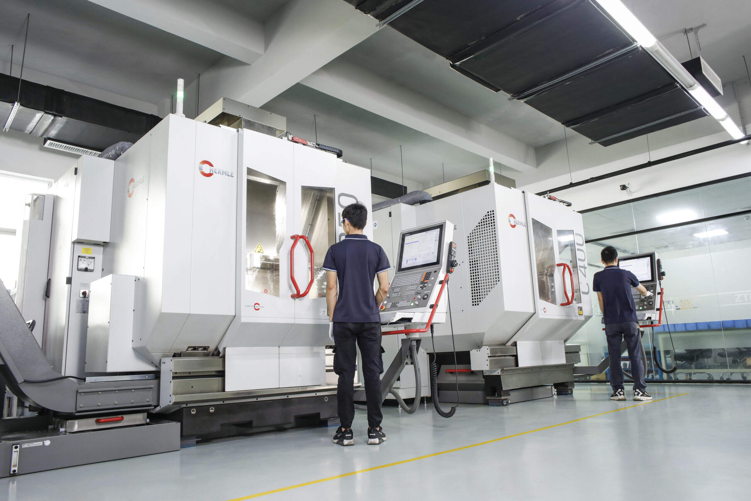
Selecting the Right Metal CNC Service Provider
Your designs are optimized, your specifications are clear, and you understand what drives costs. Now comes the decision that determines whether your project succeeds or stalls: choosing the right manufacturing partner. Search for "cnc machine shop near me" or "machinist near me" and you'll find dozens of options—but capability claims on websites rarely tell the full story.
The difference between a reliable partner and a problematic supplier often becomes apparent only after you've committed. By then, missed deadlines, quality issues, and communication breakdowns have already cost you time and money. How do you evaluate metal machining providers before problems emerge?
Evaluating CNC Service Provider Capabilities
According to JLCCNC's evaluation guide, not all CNC machining companies are created equal. Some specialize in basic milling or prototyping, while others offer advanced capabilities like 5-axis machining, Swiss turning, or EDM. Your first task is matching provider capabilities to your actual requirements.
Start by examining their equipment list. A well-equipped cnc shop near me should have:
- Diverse machine types: 3-axis mills for basic work, 5-axis machines for complex geometries, CNC lathes for rotational components
- Modern technology: Automated tool changers and in-process inspection systems indicate serious investment in capability
- Quality measurement equipment: CMM (Coordinate Measuring Machines) enable verification of tight tolerances that simple calipers cannot confirm
Material experience matters equally. As noted in JUPAICNC's engineering checklist, different projects may require specific materials with particular properties—strength, corrosion resistance, or thermal stability. A professional cnc service must be capable of working with a broad range of materials while maintaining desired quality standards.
Ask potential suppliers directly: What's the minimum tolerance they consistently hold? Can they provide case studies or sample parts from your industry? Look for services advertising tolerance capabilities within ±0.005mm or better for precision applications.
From Prototype to Production Partnership
Here's where many engineering projects fail: the transition from prototype to production. According to Zenith Manufacturing's partner selection framework, the most dangerous transition happens when jumping from prototype quantities to low-volume production. The risks and requirements differ fundamentally.
A prototype validates your design. Production validates the manufacturing process itself. Choosing a provider who understands this distinction prevents costly surprises when you're ready to scale.
Evaluate providers using this priority-ordered framework:
- Request DFM feedback before committing: Send your part drawing and observe how they respond. Do they simply quote the price, or do they ask clarifying questions about functionality, suggest improvements, and identify potential manufacturing challenges? As noted by manufacturing experts, as much as 80% of a product's cost gets locked in during the design phase. A partner providing design for manufacturability feedback actively saves you money.
- Verify unified manufacturing capability: Determine whether your supplier manufactures in-house or acts as a middleman routing work to third parties. Ask directly: "Will my prototype and production parts be made on the same equipment, by the same team?" Consistency between development and production phases prevents qualification headaches later.
- Confirm quality management systems: Request specific deliverables—First Article Inspection reports, material certifications, and SPC (Statistical Process Control) data. Don't accept vague promises. Certified facilities document everything.
- Assess communication responsiveness: When technical issues arise, you need direct access to engineers who understand your requirements—not just sales representatives. Test this during the quoting process. How quickly do they respond? How thoroughly do they address technical questions?
- Evaluate scalability: Can they grow from 10 parts to 10,000 without retooling delays or outsourcing? Ask about daily capacity, machine availability, and whether they support blanket orders or scheduled deliveries.
The goal isn't finding the lowest quote—it's finding the partner with zero management cost. Suppliers who proactively identify issues, communicate clearly, and deliver consistently save you far more than any discount on unit pricing.
What to Look for in a Long-Term Manufacturing Partner
Lead time reliability separates capable suppliers from frustrating ones. When evaluating cnc machining near me options, ask specifically about:
- Typical turnaround for prototype quantities versus production runs
- Rush job availability and associated costs
- How they handle unforeseen delays or material shortages
Some of the best metal CNC service providers offer 3-7 day turnaround on low-volume aluminum or plastic parts. For demanding applications, facilities offering one-day lead times for prototypes while maintaining production-grade quality demonstrate the operational capability needed for demanding supply chains.
Shaoyi Metal Technology exemplifies this prototype-to-production capability for automotive applications. Their IATF 16949 certification and strict Statistical Process Control protocols deliver high-tolerance components with lead times as fast as one working day. Whether you need complex chassis assemblies or custom metal bushings, their automotive machining services scale seamlessly from rapid prototyping to mass production—the exact capability profile that reduces qualification time and ensures consistency across your program lifecycle.
Beyond technical capability, evaluate cultural fit. Does the provider's communication style match your expectations? Do they take ownership of problems or deflect responsibility? A strong manufacturing partnership functions like an extension of your engineering team—not an adversarial vendor relationship.
Finally, consider the total cost equation. As Zenith Manufacturing notes, procurement teams often focus on unit price while ignoring the most expensive variable: your time. A supplier charging slightly more per part but requiring zero management intervention delivers better value than a cheaper option demanding constant oversight, rework coordination, and deadline extensions.
The right metal CNC service partner transforms manufacturing from a bottleneck into a competitive advantage. They catch design issues before production, maintain quality without constant supervision, and scale with your business as volumes grow. Invest the upfront effort in thorough evaluation—it pays dividends throughout your product lifecycle.
Frequently Asked Questions About Metal CNC Service
1. How much does CNC service cost?
Metal CNC service costs vary based on several key factors: material selection (titanium costs significantly more than aluminum), part complexity and machining time, tolerance requirements (tighter tolerances mean slower speeds and more inspection), quantity ordered, and finishing requirements. Hourly machine rates typically range from $50-200 depending on equipment sophistication, with 5-axis machining commanding premium rates. Single prototypes cost more per unit than production runs because setup costs get distributed across fewer parts. To reduce costs, simplify geometries, specify appropriate tolerances only where needed, choose readily available materials, and design for standard tooling.
2. What is the hourly rate for a CNC machine?
CNC machine hourly rates depend on equipment type and complexity. Standard 3-axis milling machines typically charge $50-80 per hour, while advanced 5-axis CNC machining services can reach $150-200 per hour due to specialized equipment and programming requirements. These rates include machine operation, energy costs, and operator time. Additional costs for setup, programming, inspection, and finishing operations are typically calculated separately. Volume orders reduce effective hourly costs since setup time distributes across more parts.
3. How much does CNC milling cost per hour?
CNC milling costs average $50-200 per hour depending on machine sophistication and project requirements. Basic 3-axis milling for simple geometries falls on the lower end, while complex multi-axis operations requiring precision tolerances command higher rates. Beyond hourly machine time, total project costs include programming and setup (often several hours for complex parts), material costs, tooling wear, inspection time, and any secondary operations like finishing or heat treatment. For accurate estimates, request detailed quotes specifying quantities at multiple volume levels.
4. What tolerances can metal CNC machining achieve?
CNC machining achieves exceptional precision across three main tolerance tiers. Standard tolerance (±0.005 inch/0.127mm) suits general-purpose applications like brackets and enclosures. Precision tolerance (±0.001 inch/0.025mm) serves parts requiring precise fits such as bearing housings and shaft interfaces. High-precision tolerance (±0.0005 inch or tighter) is reserved for aerospace, medical devices, and precision instruments requiring specialized equipment and climate-controlled environments. Tighter tolerances increase costs due to slower machining speeds, extensive inspection, and higher rejection rates—apply them only where function demands.
5. What certifications should I look for in a CNC machining provider?
Essential certifications vary by industry application. ISO 9001 provides the baseline quality management standard any reputable provider should hold. IATF 16949 certification is mandatory for automotive applications, requiring Statistical Process Control and rigorous quality documentation. AS9100D covers aerospace manufacturing with emphasis on traceability and risk management. ISO 13485 applies to medical device machining with patient safety as priority. ITAR registration is required for defense-related components. These certifications guarantee documented procedures, regular audits, complete traceability, and continuous improvement—reducing defects and ensuring consistent quality.