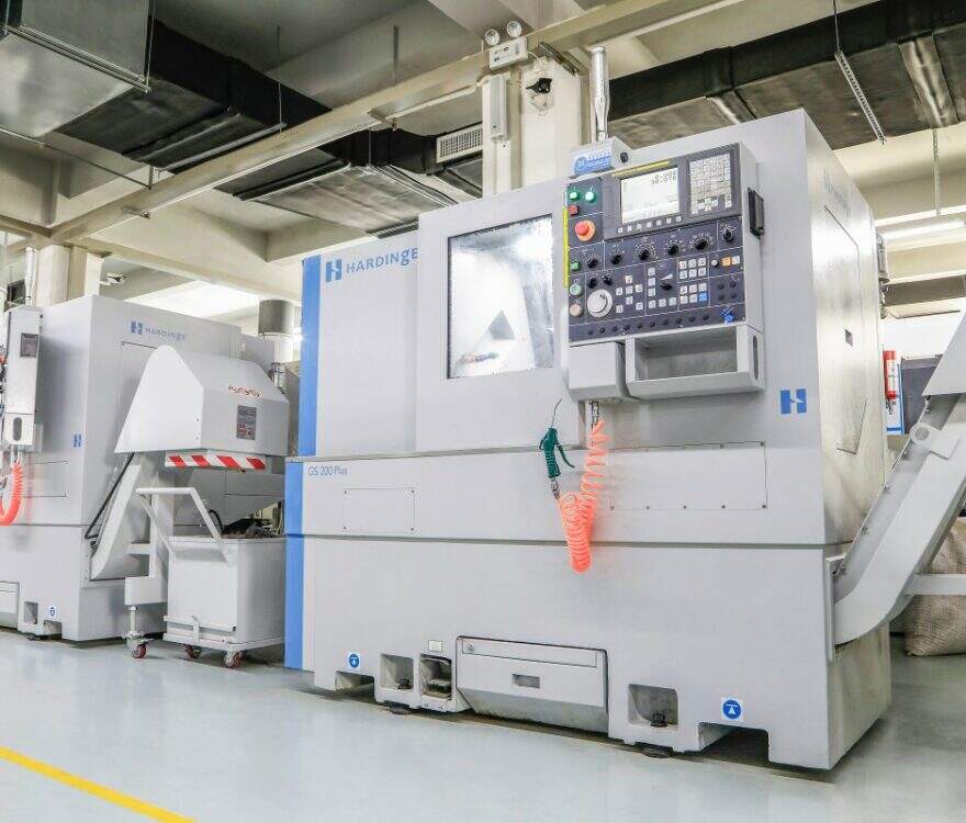
 Small batches, high standards. Our rapid prototyping service makes validation faster and easier —

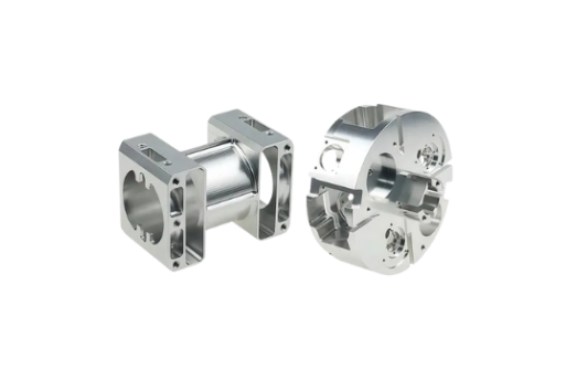
Custom CNC Machining Services: 10 Factors That Slash Costs And Lead Times
Understanding Custom CNC Machining Services and Their Role in Modern Manufacturing
Ever wondered how engineers transform complex digital blueprints into tangible, high-precision components? The answer lies in custom CNC machining services, a manufacturing approach that bridges the gap between imagination and physical reality with remarkable accuracy.
From Digital Design to Physical Part
CNC machining, or Computer Numerical Control machining, uses pre-programmed computer software to control machine tools like mills, lathes, and routers. Instead of manual operation, digital instructions guide every cut, drill, and contour. You start with a CAD (Computer-Aided Design) file, which specialized software converts into G-code—the language CNC machines understand. This code dictates precise movements, speeds, depths, and cutting paths, enabling the creation of parts with tolerances as fine as ±0.001 inches.
The result? Complex geometries that would be nearly impossible to achieve by hand become routine. Whether you need a single prototype or a batch of specialized components, this precision cnc machining process delivers consistent results every time.
What Makes CNC Machining Custom
Standard CNC machining excels at producing large volumes of identical parts based on predetermined specifications. It is streamlined for efficiency and cost-effectiveness in mass production. Custom CNC machining services, however, take a fundamentally different approach.
When you work with a custom cnc service, each project receives individual attention tailored to your unique requirements. This bespoke methodology addresses challenges that off-the-shelf solutions simply cannot solve.
- Unique specifications: Custom services accommodate non-standard dimensions, unusual geometries, and complex internal features that standard machining cannot fulfill.
- Material flexibility: From aerospace-grade titanium to medical-grade PEEK plastics, custom providers work with specialized materials matched to your application demands.
- Tolerance precision: Projects requiring ultra-tight tolerances receive dedicated programming, tooling, and inspection protocols.
- Industry certifications: Custom shops often maintain specialized certifications like AS9100 for aerospace or ISO 13485 for medical devices, ensuring compliance with sector-specific requirements.
- Low-volume capability: Unlike standard operations optimized for mass production, custom machining efficiently handles prototypes, one-off components, and small batches.
Searching for "cnc near me" might yield dozens of results, but not all providers offer true custom capabilities. The distinction matters when your project demands more than generic solutions.
The Evolution of Precision Manufacturing
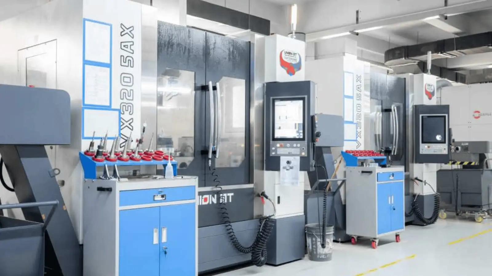
Modern CNC capabilities have expanded dramatically beyond their origins. Today's machines operate across multiple axes simultaneously, enabling the creation of intricate parts that were once impossible to manufacture. Five-axis machining centers can approach workpieces from virtually any angle, producing complex aerospace turbine blades or patient-specific medical implants in single setups.
This evolution has opened doors across diverse industries. Aerospace engineers rely on cnc fabrication for lightweight structural brackets from titanium alloys. Medical device manufacturers produce biocompatible surgical instruments with exacting surface finishes. Automotive companies accelerate development cycles through rapid prototyping. Electronics firms create precision heatsinks and enclosures optimized for thermal management.
The integration of AI-driven automation and advanced quality control systems continues pushing boundaries. Real-time monitoring, predictive maintenance, and in-process inspection now ensure that every component meets specifications before leaving the machine. For engineers and procurement professionals seeking reliable manufacturing partners, understanding these capabilities is the first step toward optimizing both costs and lead times.
Core CNC Machining Processes and When to Use Each Method
Choosing the right machining process can make or break your project's timeline and budget. Should your component be turned or milled? Is 3-axis machining sufficient, or does the design demand 5-axis capabilities? Understanding these fundamental processes helps you communicate more effectively with your manufacturing partner and avoid costly mistakes before production begins.
CNC Milling Explained
In CNC machining milling, the workpiece remains stationary while a rotating multi-point cutting tool removes material layer by layer. Imagine peeling away excess material to reveal the precise shape hidden within. This approach excels at producing flat surfaces, slots, pockets, and intricate 3D contours.
The flexibility of milling comes from its axis configurations:
- 3-axis milling: The cutting tool moves along X, Y, and Z linear axes. This handles most planar tasks like drilling, pocketing, and facing. It is cost-effective and widely accessible but requires repositioning the workpiece for complex geometries.
- 4-axis milling: Adds rotation around one axis, typically the X-axis. This enables machining of features on multiple sides without manual repositioning, reducing setup time and improving accuracy.
- 5-axis machining services: The tool or table can tilt and rotate, providing access from virtually any angle. This capability minimizes setups, reaches difficult surfaces, and produces smoother finishes on contoured parts like turbine blades, impellers, and medical implants.
When your design includes angular cuts, holes at compound angles, or complex 3D surfaces, CNC milling parts become the logical choice. Face mills, end mills, ball-nose cutters, and chamfer tools each serve specific purposes, from aggressive roughing passes to delicate finishing operations.
When CNC Turning Makes Sense
CNC turning flips the script entirely. Here, the workpiece spins at high speed while a stationary single-point cutting tool shapes the surface. Think of it as a potter's wheel for metal, only with computer-controlled precision measured in thousandths of an inch.
This process shines for components with rotational symmetry—shafts, pins, bushings, pulleys, and threaded rods. Because the part rotates around a central axis, turning maintains exceptional concentricity and roundness. For high-volume production of cylindrical components, a CNC turning service delivers unmatched efficiency.
Modern turning centers extend these capabilities further:
- Live tooling: Rotating tools mounted on the turret can perform milling operations like drilling cross-holes or cutting keyways without transferring the part to a separate machine.
- Sub-spindles: A secondary spindle grabs the workpiece for backside operations, completing parts in a single cycle.
- Bar feeders: Automated material supply enables continuous production runs with minimal operator intervention.
If your component starts as round bar stock and features primarily concentric diameters, internal bores, threads, or grooves, CNC turning services typically offer faster cycle times and lower per-part costs than milling the same geometry.
Multi-Axis Machining for Complex Geometries
What happens when your design combines cylindrical features with milled flats, angled holes, or intricate contours? This is where 5 axis cnc machining services and hybrid mill-turn centers prove their value.
Five-axis machines approach the workpiece from virtually any direction, eliminating the need for multiple setups. Continuous tool orientation reduces repositioning errors and dramatically improves surface finish quality on sculptured surfaces. Aerospace components, orthopedic implants, and automotive molds frequently demand these capabilities.
Mill-turn centers merge both processes into a single platform. The workpiece can rotate like a lathe while live tooling performs milling operations—all without unclamping. A flanged shaft with milled slots and drilled cross-holes becomes a single-setup job rather than a multi-machine odyssey.
Secondary operations often complement these primary processes:
- CNC drilling: Creates initial holes quickly and cost-effectively.
- Boring: Enlarges and aligns holes with improved cylindrical precision.
- Reaming: Achieves exact dimensions and mirror-smooth internal surfaces.
- Grinding: Produces ultra-fine surface finishes and tight tolerances on hardened materials.
Matching Part Requirements to Machining Methods
Selecting the optimal process starts with examining your part's geometry. The following comparison highlights key decision factors:
| Factor | CNC Milling | CNC Turning |
|---|---|---|
| Typical Applications | Housings, brackets, molds, engine blocks, prismatic parts | Shafts, pins, bushings, rollers, threaded rods, cylindrical components |
| Part Geometries | Flat surfaces, slots, pockets, 3D contours, multi-face features | Cylindrical, conical, rotational symmetry around central axis |
| Tolerance Capabilities | ±0.001" to ±0.005" typical; tighter with 5-axis | ±0.001" to ±0.002" for roundness and concentricity |
| Ideal Stock Material | Flat plates, rectangular blocks | Round bars, tubes |
| Setup Complexity | Higher for multi-sided parts; reduced with 5-axis | Generally simpler for symmetric parts |
| Production Efficiency | Best for complex, low-to-medium volumes | Excellent for high-volume cylindrical parts |
Consider this practical guidance when planning your next project:
- Parts with primarily round features and concentric diameters lean toward CNC turning for speed and cost efficiency.
- Designs requiring flat faces, pockets, or angular features suit milling operations.
- Components combining both rotational and prismatic features benefit from mill-turn centers or sequential operations.
- Intricate 3D surfaces, undercuts, and multi-angle access points justify the investment in 5-axis capabilities.
Understanding these fundamental processes positions you to have more productive conversations with your machining partner. With the right process selected, the next critical decision involves choosing materials that balance performance requirements with machinability and cost.
Material Selection Guide for Custom CNC Parts
You've defined your part geometry and selected the right machining process. Now comes a decision that directly impacts performance, cost, and lead time: which material should you choose? The wrong selection can mean premature failure in the field, excessive tool wear during production, or budget overruns that derail your project.
Unlike generic material lists that leave you guessing, this guide provides decision-making frameworks. You'll understand not just what materials are available, but when each one makes sense for your specific application.
Aluminum Alloys for Lightweight Applications
When engineers need an excellent strength-to-weight ratio combined with outstanding machinability, aluminum alloys consistently top the list. These cnc machining materials offer natural corrosion resistance, high thermal and electrical conductivity, and cost efficiency that's hard to beat.
But not all aluminum is created equal. Here's how to choose between the most common grades:
- Aluminum 6061: The workhorse of custom CNC machining. This general-purpose alloy delivers good strength, excellent machinability, and welds easily. Choose 6061 for brackets, fixtures, housings, and prototypes where cost efficiency matters more than maximum strength.
- Aluminum 7075: Need aerospace-grade performance? This alloy approaches steel-level strength while maintaining aluminum's weight advantage. Heat-treatable to high hardness, 7075 excels in aircraft structural components, high-stress brackets, and performance automotive parts. Expect higher material costs and slightly reduced machinability compared to 6061.
- Aluminum 5083: When your part faces seawater or marine environments, this alloy's exceptional corrosion resistance justifies the selection. It also welds beautifully, making it ideal for boat components and marine hardware.
All aluminum alloys can be anodized to create a hard, protective surface layer that enhances wear resistance and allows for color options. This finishing flexibility adds another advantage to an already versatile material family.
Engineering Plastics and Their Advantages
Metal isn't always the answer. Engineering plastics deliver lightweight solutions with unique properties that metals simply cannot match—chemical resistance, electrical insulation, and self-lubricating behavior that eliminates the need for external lubricants.
Two materials dominate this category: Delrin plastic and nylon for machining applications.
Delrin (POM/Acetal) stands out as the most machinable plastic available. Its combination of high stiffness, low friction, and excellent dimensional stability makes it ideal for precision parts that must maintain tight tolerances. Consider Delrin when designing:
- Gears and bearings requiring smooth, quiet operation
- Electrical connectors demanding dimensional precision
- Food processing components needing FDA-compliant materials
- Parts exposed to moisture where dimensional stability matters
Machining nylon offers a different property profile. Nylon absorbs more moisture than Delrin—up to 8% compared to Delrin's near-zero absorption—which can affect dimensions in humid environments. However, nylon's superior toughness and flexibility make it better suited for applications involving impact forces or mechanical shock.
Choose nylon when your design requires:
- High impact resistance without cracking
- Flexibility combined with wear resistance
- Components operating at elevated temperatures (nylon handles heat slightly better than Delrin)
- Gears and rollers in industrial conveyor systems
Other engineering plastics serve specialized roles. PEEK handles extreme temperatures and offers biocompatibility for medical implants. Polycarbonate provides optical clarity with excellent impact strength. PTFE (Teflon) delivers the lowest friction coefficient of any solid material.
Specialty Metals for Demanding Environments
Some applications demand material properties that aluminum and standard steels cannot provide. This is where specialty metals earn their premium pricing.
Stainless Steel combines strength with corrosion resistance. Type 304 handles most general applications, while 316 offers superior resistance to chlorides and saltwater. For extreme environments like offshore oil platforms, 2205 Duplex delivers twice the strength of standard stainless grades. These materials cost more and machine harder than aluminum, requiring slower feeds and carbide tooling.
Bronze CNC machining serves applications where other materials simply cannot perform. When you need to machine bronze, you're typically addressing bearing surfaces, bushings, or components requiring exceptional wear resistance combined with corrosion immunity.
Key bronze alloys for CNC machining bronze applications include:
- C932 Bearing Bronze (SAE 660): The go-to choice for bearings and bushings. Excellent wear resistance, anti-friction properties, and good machinability make it ideal for valve components and thrust washers.
- C954 Aluminum Bronze: When you need strength approaching steel combined with outstanding corrosion resistance, especially in marine environments. Used for pump shafts, heavy-duty bearings, and wear plates.
- C510 Phosphor Bronze: Superior fatigue resistance and elasticity suit electrical contacts, springs, and components experiencing repeated stress cycles.
Machining bronze presents unique challenges. C932 bronze creates long, stringy chips requiring sharp tools and appropriate chip-breaking strategies. C954's high strength demands carbide tooling and controlled cutting speeds. These factors add to cycle time and cost compared to aluminum or brass.
How Material Choice Affects Your Bottom Line
Every material decision cascades through your project's economics. Harder materials wear tools faster, increasing tooling costs. Difficult-to-machine alloys require slower feeds and speeds, extending cycle times. Specialty materials may have longer procurement lead times.
The following comparison helps you balance performance requirements against manufacturing realities:
| Material Category | Key Properties | Typical Applications | Relative Machinability |
|---|---|---|---|
| Aluminum 6061 | Lightweight, corrosion resistant, excellent conductivity | Brackets, housings, prototypes, fixtures | Excellent (baseline) |
| Aluminum 7075 | High strength, heat treatable, fatigue resistant | Aerospace structures, high-stress components | Good |
| Stainless Steel 304/316 | Corrosion resistant, high strength, weldable | Medical devices, food equipment, marine hardware | Moderate |
| Delrin (POM) | Low friction, dimensionally stable, moisture resistant | Gears, bearings, electrical connectors | Excellent |
| Nylon 6/66 | Tough, flexible, wear resistant, absorbs moisture | Industrial rollers, gears, impact-resistant parts | Good |
| C932 Bronze | Wear resistant, anti-friction, corrosion resistant | Bearings, bushings, valve components | Good |
| C954 Aluminum Bronze | High strength, marine corrosion resistant | Pump shafts, marine components, wear plates | Moderate to Low |
Industry certifications add another consideration. Aerospace applications may require materials meeting specific AMS specifications. Medical devices often demand biocompatibility testing and FDA-compliant materials. Automotive components might need materials traceable to IATF 16949-certified supply chains.
The most cost-effective approach? Start with your functional requirements—strength, corrosion resistance, weight, operating temperature—then identify the least expensive material that meets all criteria. Overspecifying materials wastes money; underspecifying risks field failures.
With material selection complete, the next factor influencing both cost and quality becomes tolerance specifications. Understanding how precision requirements impact manufacturing helps you specify exactly what your application needs—nothing more, nothing less.
Tolerance Specifications and Precision Capabilities Explained
Imagine ordering a custom part only to discover it doesn't fit during assembly. The hole is too tight, the shaft won't slide into the bearing, or the mating surfaces don't align. What went wrong? In most cases, the answer lies in tolerance specifications—those seemingly small numbers that determine whether your precision machining parts perform flawlessly or fail catastrophically.
Tolerances define the acceptable variation in a dimension. They're the difference between a part that costs $50 and one that costs $200. Understanding how to specify them correctly protects both your budget and your product's functionality.
Standard vs Tight Tolerance Specifications
Every machining operation produces slight variations. No two parts are ever perfectly identical. Tolerances acknowledge this reality by establishing acceptable boundaries for dimensional deviation.
Standard machining tolerances typically fall within ±0.005" (±0.127mm). Most CNC machines achieve this level without special procedures, making it cost-effective for the majority of applications. According to Protolabs, these bilateral tolerances work well for non-critical dimensions where exact precision isn't functionally necessary.
Tight tolerances—±0.001" (±0.025mm) or tighter—demand fundamentally different approaches. Machines run slower. Tools require more frequent replacement. Temperature control becomes critical because thermal expansion affects measurements. Every part needs individual inspection rather than statistical sampling.
Here's how common tolerance ranges align with typical applications:
- ±0.005" (±0.127mm): General-purpose machined parts, brackets, housings, non-critical features
- ±0.002" (±0.05mm): Precision fits, bearing housings, alignment features requiring moderate accuracy
- ±0.001" (±0.025mm): Close-fitting assemblies, sealing surfaces, aerospace and medical components
- ±0.0005" (±0.0127mm): High-precision instruments, optical equipment, critical mating surfaces
- ±0.0001" (±0.0025mm): Ultra-precision applications requiring specialized equipment and climate-controlled environments
The key insight? Reserve tight tolerances for features where dimensional variation directly impacts function. A shaft running in a bearing needs precision. The external corner of a housing does not.
Understanding GD&T Basics
Traditional plus-minus tolerancing handles length, width, and hole size effectively. But what about ensuring a surface is truly flat? Or that a hole sits exactly perpendicular to a reference surface? This is where Geometric Dimensioning and Tolerancing (GD&T) becomes essential.
GD&T provides a standardized symbolic language—defined in ASME Y14.5—that communicates geometric relationships between part features. Rather than simply stating dimensions, GD&T controls how features relate to each other in 3D space.
The most commonly applied GD&T controls include:
- Flatness: Ensures a surface lies between two parallel planes separated by the specified tolerance. Critical for sealing surfaces and mounting faces where warpage could prevent proper contact.
- Perpendicularity: Controls the squareness of one surface or axis relative to a datum. Essential when components must assemble at precise right angles.
- Position: Defines where a feature (typically a hole) must be located relative to datum references. Uses true position rather than bilateral tolerancing, often with Maximum Material Condition (MMC) or Least Material Condition (LMC) modifiers that provide bonus tolerance.
- Cylindricity: Controls the roundness and straightness of cylindrical features simultaneously. Prevents holes or shafts from being oblong or tapered.
- Concentricity: Ensures that multiple circular features share a common axis, like the wheels on your car sharing an axle centerline.
GD&T adds complexity to drawings and inspection requirements. However, for assemblies with multiple mating parts, it often provides more functional tolerance than traditional methods while maintaining fit requirements. A precision machining service with GD&T expertise can guide you toward specifications that optimize both quality and cost.
How Tolerance Choices Affect Your Budget
Here's the uncomfortable truth: tighter tolerances cost exponentially more. Industry data reveals that specifying ±0.001" precision costs 3-4x more than standard ±0.005" tolerances. Push to ±0.0001", and costs can escalate 10-24x higher than baseline.
Where does this cost explosion come from?
- Extended machining time: Achieving ±0.001" requires slower feeds, lighter cuts, and multiple finishing passes. A part taking 10 minutes at standard tolerance might need 30 minutes for tight specifications.
- Specialized equipment: Ultra-tight tolerances demand climate-controlled environments where temperature fluctuations don't affect measurements. High-precision machines with superior rigidity and positioning accuracy become necessary.
- Intensive inspection: Standard parts undergo statistical sampling. Tight tolerance work often requires 100% dimensional verification using coordinate measuring machines (CMMs), adding $50-150 per part for comprehensive measurement and documentation.
- Higher scrap rates: With narrower acceptable ranges, more parts fall outside specification. Material waste and rework costs accumulate.
- Tooling costs: Maintaining sharp cutting edges becomes critical. Tools are replaced more frequently, and specialized geometries may be required.
Lead times stretch correspondingly. Standard tolerance parts might ship in 5-7 days, while cnc precision machining services delivering ±0.001" specifications typically need 10-14 days. Ultra-tight tolerances can extend timelines to 3 weeks or more.
Design Takeaway: Evaluate each tolerance based on functional necessity. Ask "what happens if this dimension varies by ±0.05mm?" If the answer is "nothing critical," use standard tolerances to reduce cost, complexity, and inspection requirements.
The most effective strategy? Apply tight tolerances only to the 10-20% of features that truly require them—mating surfaces, sealing interfaces, and precision fits. Let everything else default to standard specifications. This selective approach can reduce manufacturing costs by 40-60% while maintaining the precision that actually matters for your application.
With tolerance requirements defined, the next consideration involves surface finish specifications—another factor that significantly impacts both aesthetics and functionality while influencing your project's cost and timeline.
Surface Finish Options and Specifications
Your part dimensions are perfect. Tolerances meet spec. But when the components arrive, the surfaces look rough, feel abrasive, or start corroding within weeks. What went wrong? Surface finish specifications were either overlooked or poorly matched to the application's actual requirements.
Surface finish impacts far more than aesthetics. It determines friction coefficients, wear resistance, corrosion protection, and even how well sealing surfaces mate. Understanding your options—and their cost implications—helps you specify exactly what your application demands.
As-Machined vs Secondary Finishing
Every CNC machined part leaves the machine with visible tool marks following the cutting path. This as-machined condition represents your most economical option, but it comes with trade-offs you should understand.
Surface quality is measured using Ra (Roughness Average), expressed in micrometers (μm) or microinches (μin). According to Hubs, standard as-machined Ra is 3.2 μm (125 μin). A finishing cutting pass can improve this to 1.6, 0.8, or even 0.4 μm (63, 32, or 16 μin)—but each improvement adds machining steps and cost.
When does as-machined finish make sense?
- Internal components: Parts hidden from view where appearance doesn't matter
- Prototype validation: Testing fit and function before investing in surface treatments
- Tight tolerance features: Secondary finishing removes material, potentially affecting critical dimensions
- Cost-sensitive applications: When budget constraints outweigh cosmetic requirements
The key advantage? No added cost beyond standard machining, and you maintain the tightest dimensional tolerances since no material is removed post-machining.
However, visible tool marks may be unacceptable for customer-facing products. Rough surfaces can trap contaminants in food or medical applications. And without protective treatment, many metals begin corroding immediately when exposed to moisture or chemicals.
Anodizing and Protective Coatings
When your cnc aluminum parts need corrosion protection, wear resistance, or cosmetic appeal, secondary finishes transform raw machined surfaces into durable, functional exteriors.
Bead Blasting uses pressurized glass beads to create a uniform matte or satin texture. This process removes tool marks and produces a consistent appearance across the entire part. It's primarily aesthetic but also provides a good base for subsequent coatings. Critical features like threaded holes can be masked to prevent dimensional changes. Expect this to add minimal cost while significantly improving visual appeal.
Anodizing creates an integral ceramic oxide layer on aluminum and titanium surfaces through an electrochemical process. Unlike paint that sits on top, anodizing actually converts the surface material into hard aluminum oxide. This coating is nonconductive and exceptionally durable.
Two primary types serve different needs:
- Type II (Standard/Decorative): Produces oxide layers typically 4–12 μm thick. Improves surface smoothness, provides good corrosion resistance, and accepts dyes for color options. Black-dyed parts commonly fall in the 8–12 μm range.
- Type III (Hardcoat): Creates much thicker layers, typically around 50 μm but achievable up to 125 μm. Delivers superior wear and corrosion resistance for demanding functional applications. The process requires tighter control, including solution temperatures maintained near 0°C, which increases cost significantly.
One critical consideration: anodizing grows both outward and inward from the original surface. A 50 μm coating extends about 25 μm above and removes about 25 μm below the original dimension. Plan for this dimensional change when specifying critical features.
Powder Coating applies a durable polymer layer through electrostatic spraying followed by oven curing. Unlike anodizing, powder coating works on any metal—not just aluminum. Typical thickness ranges from 18 μm to 72 μm, with broad color options available. This finish delivers excellent impact resistance, often outperforming anodized surfaces for applications involving mechanical contact or handling.
Plating Options deposit thin metal layers for specific functional requirements:
- Nickel plating: Provides corrosion resistance and wear protection
- Zinc plating: Cost-effective corrosion barrier for steel components
- Chrome plating: Hard, wear-resistant surface for functional applications
- Gold plating: Superior electrical conductivity for connector applications
For specialized materials like acrylic or polycarbonate, an acrylic cnc service can machine these plastics to optical clarity, though they typically receive different finishing treatments than metals. When working with an acrylic cnc machine, vapor polishing or flame polishing often replaces mechanical finishing to achieve transparent surfaces.
Matching Finish to Function
Selecting the right finish starts with understanding your surface's functional requirements—not just its appearance. Different areas of the same part may need entirely different treatments.
Consider these application categories:
- Cosmetic surfaces: Customer-facing areas where appearance matters. Bead blasting followed by anodizing produces uniform, attractive finishes. Powder coating offers unlimited color options.
- Bearing surfaces: Areas experiencing sliding contact need controlled roughness. Too smooth prevents lubricant retention; too rough accelerates wear. Typical Ra values of 0.4–1.6 μm balance these requirements.
- Sealing surfaces: Gasket and O-ring contact areas require specific roughness profiles. Too rough causes leakage; too smooth may prevent proper gasket grip. Specify Ra based on seal manufacturer recommendations.
- Electrical contact surfaces: May require plating for conductivity while other areas are anodized for insulation.
The following comparison helps match finish types to your requirements:
| Finish Type | Typical Ra Value | Appearance | Recommended Applications |
|---|---|---|---|
| As-Machined (Standard) | 3.2 μm (125 μin) | Visible tool marks | Internal parts, prototypes, cost-sensitive applications |
| As-Machined (Fine) | 0.8–1.6 μm (32–63 μin) | Minimal tool marks | Bearing surfaces, sealing faces, precision fits |
| Bead Blasted | 1.6–3.2 μm (63–125 μin) | Uniform matte/satin | Cosmetic parts, preparation for coating |
| Anodize Type II | 0.5–1.5 μm after process | Smooth, dyed colors available | Aluminum housings, consumer products, electronics enclosures |
| Anodize Type III | 1.0–2.0 μm | Matte, typically darker | High-wear components, aerospace parts, military applications |
| Powder Coated | Varies by powder | Smooth to textured, broad colors | Enclosures, outdoor equipment, consumer products |
Surface finish directly impacts both cost and lead time. Bead blasting adds 1-2 days and minimal expense. Type II anodizing typically extends lead times by 3-5 days. Type III hardcoat anodizing—the most expensive option discussed—can add a week or more while significantly increasing per-part costs.
The most cost-effective approach? Specify finishes based on functional zones. Apply premium treatments only where performance demands them, and allow standard as-machined conditions for non-critical areas. This selective specification can reduce finishing costs by 30-50% while still delivering the performance characteristics your application requires.
With surface finish requirements defined, the next decision involves determining whether CNC machining is even the right manufacturing method for your project—or whether alternative processes might better serve your needs.
CNC Machining vs Alternative Manufacturing Methods
You've defined your part specifications, selected materials, and established tolerance requirements. But before requesting quotes, ask yourself a critical question: is CNC machining actually the best manufacturing method for this project? Choosing the wrong process wastes time, inflates costs, and delays your timeline.
Each manufacturing method excels in specific scenarios. Understanding these distinctions helps you make informed decisions—and potentially saves thousands of dollars while accelerating delivery.
CNC vs 3D Printing Decision Factors
CNC machining and 3D printing represent fundamentally opposite approaches. CNC subtracts material from solid blocks; 3D printing builds objects layer by layer from nothing. This distinction drives their respective strengths and limitations.
According to Fictiv, CNC machining delivers superior precision, part strength, and surface finish quality. When your cnc prototype must withstand stress testing, harsh environments, or functional validation with production-grade materials, machining wins decisively.
Choose CNC machining when your project requires:
- Tight tolerances: CNC achieves ±0.001" or better; most 3D printing struggles below ±0.005"
- Material performance: Full-strength metals, engineering plastics with known mechanical properties
- Surface finish quality: Smooth finishes with minimal post-processing
- Functional testing: Parts that must perform identically to production components
3D printing outperforms CNC machining in different scenarios:
- Complex internal geometries: Lattice structures, internal channels, and organic shapes impossible to machine
- Rapid design iteration: Updating a CAD file and starting a new print takes hours, not days
- Lightweight optimization: Topology-optimized structures reduce weight while maintaining strength
- Low-cost visual models: When appearance matters more than performance
The cost equation shifts with quantity. 3D printing maintains consistent per-part costs regardless of volume—printing one part costs the same as printing the hundredth. CNC prototype machining has higher setup costs but becomes increasingly economical as quantities increase.
When Injection Molding Beats Machining
For plastic parts, injection molding represents the gold standard for high-volume production. Once tooling is complete, the process delivers remarkable consistency, speed, and per-part economics that machining cannot match.
However, injection molding requires significant upfront investment. Mold tooling costs range from $3,000 for simple geometries to $100,000+ for complex multi-cavity tools. This investment only makes sense when production volumes justify it.
Consider injection molding when:
- Quantities exceed 500-1,000 units: The break-even point where tooling costs amortize effectively
- Part geometry is fixed: Design changes require expensive mold modifications
- Cycle time matters: Injection molding produces parts in seconds, not minutes
- Material variety is needed: Thousands of plastic formulations offer tailored properties
Prototype machining services bridge the gap beautifully. Use CNC to validate designs before committing to injection mold tooling. A machined prototype costs $200-500 and ships in days; discovering a design flaw after cutting a $50,000 mold proves catastrophic.
As Protolabs notes, many successful products transition through multiple processes—3D printing for concept models, CNC machining for functional prototypes, then injection molding for production volumes.
Alternative Methods for Specific Applications
Sheet metal fabrication excels for thin-walled enclosures, brackets, and chassis components. When your design features consistent wall thickness under 6mm, bends, and cutouts, sheet metal typically costs less than machining from solid blocks. Laser cutting combined with CNC bending produces accurate parts rapidly.
Casting becomes economical for complex shapes in moderate-to-high volumes. Investment casting (lost-wax) handles intricate geometries in various metals. Die casting delivers excellent dimensional consistency for aluminum and zinc parts. Both require tooling investment but offer material efficiency that machining cannot match for certain geometries.
Carbon fiber prototyping addresses applications demanding extreme strength-to-weight ratios. While CNC machines can cut carbon fiber sheets and tubes, composite layup processes create complex curved structures that machining cannot produce.
Hybrid Manufacturing Approaches
The future of manufacturing increasingly combines multiple processes. According to All3DP, hybrid manufacturing—integrating 3D printing with CNC machining—has slashed lead times from 10 weeks to 72 hours in some applications while reducing material waste by up to 97%.
Practical hybrid strategies include:
- 3D print near-net shapes, then machine critical features: Additive creates complex geometry; CNC delivers precision where tolerances matter
- Rapid cnc prototyping for validation, then 3D-printed tooling for production: Confirm designs before investing in conventional molds
- CNC-machined components assembled with 3D-printed fixtures: Custom assembly tools printed overnight accelerate production
This combined approach leverages each method's strengths while minimizing weaknesses. Complex internal channels are printed; mating surfaces are machined to precision.
Choosing the Right Method for Your Project
The following comparison helps you quickly identify which manufacturing method best suits your requirements:
| Factor | CNC Machining | 3D Printing | Injection Molding | Sheet Metal |
|---|---|---|---|---|
| Ideal Quantities | 1–10,000 | 1–100 | 500–1,000,000+ | 10–10,000 |
| Tolerance Capabilities | ±0.001" achievable | ±0.005" typical | ±0.002" typical | ±0.010" typical |
| Material Options | Metals, plastics, composites | Plastics, resins, some metals | Thermoplastics primarily | Sheet metals only |
| Typical Lead Times | 5–15 days | 1–5 days | 4–8 weeks (with tooling) | 5–10 days |
| Setup/Tooling Cost | Low to moderate | None | High ($3K–$100K+) | Low to moderate |
| Best For | Functional parts, tight tolerances | Complex geometries, rapid iteration | High-volume plastics | Enclosures, brackets |
Ask these questions before committing to a process:
- Does my design require tolerances tighter than ±0.005"? → CNC machining
- Am I iterating through multiple design versions quickly? → 3D printing
- Will I produce more than 1,000 identical plastic parts? → Injection molding
- Is my part primarily flat with bends and cutouts? → Sheet metal
- Do I need production-grade material properties for testing? → CNC prototype machining
CNC prototyping shines brightest when you need functional validation with real materials, precise dimensional accuracy, and the flexibility to scale from one prototype to thousands of production parts using the same process. When these factors align with your project requirements, you're ready to move forward with the machining workflow—from file preparation through final delivery.
The Complete CNC Machining Workflow from Design to Delivery
You've selected CNC machining as your manufacturing method. Your design is finalized, materials are chosen, and tolerances are specified. Now what? Understanding the complete workflow—from the moment you submit files to when cnc machined parts arrive at your door—eliminates surprises and helps you plan realistic timelines.
Each stage in this process offers opportunities to accelerate delivery or reduce costs. Knowing what happens behind the scenes empowers you to prepare better files, ask smarter questions, and avoid the delays that derail project schedules.
Preparing Your CAD Files for Submission
Your CAD file is more than a visual representation—it's the mathematical blueprint that controls every tool movement. According to LeadCNC, the integrity of this file directly translates into production efficiency, material waste minimization, and component quality.
When preparing files for cnc machining parts production, format selection matters significantly:
- STEP (.step or .stp): The preferred format for B2B exchange. STEP captures exact geometry and crucial topological information, ensuring the model transfers as a true solid rather than just graphical data. Use STEP AP214 when possible—it supports color, layers, and geometry validation properties.
- IGES (.igs or .iges): An older standard that handles surface geometry but is more prone to continuity errors. Generally being superseded by STEP for robust solid modeling.
- Native CAD formats: If your manufacturing partner uses the same CAD software, native files retain feature intelligence and parametric data.
- DXF/DWG: Primarily for 2D operations like profile cutting. Useful for defining flat pattern geometries but lacking volume information.
Before submitting, run a geometric analysis to check for common issues: non-manifold edges (edges shared by more than two faces), tiny sliver faces that confuse toolpath algorithms, and open boundaries that prevent watertight solid definition. These problems propagate downstream, causing CAM failures or parts that fail quality checks.
One critical verification: confirm your units match your intent. A model designed in millimeters but interpreted as inches creates parts scaled down by a factor of 25.4—an expensive mistake that scraps entire batches.
The DFM Review Process
After file submission, experienced manufacturers conduct a Design for Manufacturability (DFM) review. This step catches issues before they become expensive problems on the shop floor.
What happens during DFM review? Engineers analyze your geometry against manufacturing constraints, identifying features that add cost, extend lead times, or risk quality issues. According to Summit CNC, following DFM best practices delivers faster, more cost-effective custom machined parts.
Key DFM guidelines to address before submission:
- Maintain minimum wall thicknesses above 0.02": Thin walls reduce weight but become brittle and prone to breaking during machining. Thicker walls machine faster with less risk.
- Avoid deep pockets with sharp internal corners: CNC tools are cylindrical—they cannot produce sharp 90-degree internal corners. Specify corner radii of at least 0.0625" to enable standard tooling. The minimum internal radius should be at least 1.2 times the tool radius you expect to be used.
- Limit pocket depths to 6x the smallest corner radius: Deeper pockets require long-reach tools prone to breakage and deflection. A pocket with 0.125" corner radii should be no deeper than 0.75" for optimal machining efficiency.
- Eliminate purely aesthetic complexity: Intricate features that don't serve functional purposes add cost without adding value. Design for function first.
- Specify chamfers rather than fillets on external edges: Chamfers require simple 2D toolpaths; fillets demand complex 3D contouring or specialized tools.
- Reserve tight tolerances for critical features: Tolerances tighter than ±0.005" increase cost through slower machining, specialized tooling, and intensive inspection. Apply precision only where function demands it.
A thorough DFM review typically adds 1-2 days but prevents weeks of delays from manufacturing issues discovered mid-production. Good partners communicate findings clearly, offering alternatives rather than simply rejecting designs.
From Quote Approval to Machining Operations
Once DFM review confirms manufacturability, the workflow progresses through several defined stages:
- Quoting and order confirmation: You receive detailed pricing reflecting material costs, machining time, finishing operations, and inspection requirements. Upon approval, production scheduling begins.
- Material procurement: Standard materials like 6061 aluminum or 304 stainless typically ship from distributors within 1-2 days. Specialty alloys, certified aerospace materials, or unusual grades may require 1-2 weeks. Confirm material lead times before committing to aggressive schedules.
- CAM programming: Engineers convert your CAD geometry into toolpaths—the precise instructions controlling cutter movements. Complex cnc milled parts with multiple setups require more programming time than simple geometries.
- Setup and fixturing: Your raw material is mounted securely in the machine. The part zero (origin point) is established relative to the workpiece. For cnc turning parts, this involves chucking round stock; for milling operations, it means clamping blocks or plates to the table.
- Machining operations: Roughing passes remove bulk material quickly. Semi-finishing operations refine geometry. Final finishing passes achieve specified tolerances and surface finish. Multi-setup parts are repositioned between operations.
- Secondary operations: Deburring removes sharp edges. Threading, tapping, or specialized hole finishing occurs as needed. Surface treatments like anodizing or plating follow machining completion.
Communication touchpoints matter throughout this process. Expect updates at order confirmation, when machining begins, and before shipping. Quality partners proactively communicate delays rather than letting deadlines slip silently.
Quality Inspection and Final Delivery
Before cnc machine parts leave the facility, inspection verifies conformance to your specifications. The inspection scope depends on your tolerance requirements and industry certifications.
Standard inspection typically includes:
- Dimensional verification: Critical features measured using calipers, micrometers, height gauges, and pin gauges. Results compared against drawing specifications.
- Visual inspection: Surface finish quality, absence of tool marks in critical areas, proper edge treatment, and cosmetic appearance evaluated.
- First article inspection (FAI): For production orders, the first completed part receives comprehensive measurement before remaining parts are machined.
Tight tolerance or certified applications require more intensive verification:
- CMM (Coordinate Measuring Machine) inspection: Programmable probes measure complex geometries with micron-level precision, generating detailed measurement reports.
- GD&T verification: Position, flatness, perpendicularity, and other geometric characteristics validated against datum references.
- Material certification: Mill test reports confirm material composition meets specifications—critical for aerospace and medical applications.
- Statistical Process Control (SPC): For production runs, measurement data tracks process stability and capability.
Inspection documentation accompanies shipment. At minimum, expect a certificate of conformance. Precision applications may include full dimensional reports, material certifications, and process documentation.
Packaging protects your investment during transit. Individual wrapping prevents part-to-part contact. Foam inserts cushion delicate features. Desiccant packets control humidity for corrosion-sensitive materials. Expedited shipping options balance speed against cost.
From file submission to delivery, a typical workflow spans 7-15 business days for standard tolerances and readily available materials. Tight tolerance work, specialty materials, or complex finishing extends timelines accordingly. Understanding each stage helps you plan realistically—and identify opportunities to accelerate delivery when schedules demand it.
With the workflow understood, the next critical factor involves managing costs and lead times strategically. Knowing what drives expenses—and which variables you control—transforms procurement from guesswork into optimization.
Cost Factors and Lead Time Optimization Strategies
You've designed your part, selected materials, and specified tolerances. Now comes the question that shapes every procurement decision: what will this actually cost, and when will it arrive? Unlike competitors who hide behind instant quote calculators, understanding the real drivers behind cnc machining price helps you make smarter decisions—and potentially save 30-50% on your next project.
The truth? Most cost and lead time variables are within your control. Small design adjustments, strategic material choices, and smart ordering practices compound into significant savings without sacrificing quality.
What Drives CNC Machining Costs
Every cnc machining part quote reflects a combination of factors. Understanding each component helps you identify where optimization opportunities exist.
Material Selection and Waste
Raw material cost extends beyond the price per pound. CNC machining is subtractive—you're paying for material that becomes chips on the floor. A part machined from a 10-pound aluminum block that finishes at 2 pounds means 80% of your material cost literally goes in the scrap bin.
According to HKAA's 2025 cost analysis, material choice dramatically impacts both raw cost and machining efficiency. Aluminum machines quickly with minimal tool wear. Stainless steel costs more per pound and requires slower feeds, carbide tooling, and more machine time. Titanium compounds these challenges further—expect 3-5x the machining time compared to aluminum for equivalent geometries.
Part Complexity and Cycle Time
Machine time is the largest cost component for most projects. Hourly rates in 2025 range from $70-125 for standard 3-axis work to $150-250 for 5-axis machining. Every minute on the machine adds directly to your invoice.
Complexity multiplies time requirements exponentially:
- Deep pockets require multiple passes with progressively longer tools
- Thin walls demand lighter cuts at slower feeds to prevent deflection
- Tight internal corners need smaller tools running at reduced speeds
- Multiple setups add repositioning time and introduce tolerance stack-up risk
Tolerance Requirements
Standard tolerances (±0.005") cost baseline rates. Tighten to ±0.001" and costs jump 3-4x. Push to ±0.0001" and you're looking at 10-24x increases. Why? Tighter specs require slower feeds, more finishing passes, climate-controlled environments, specialized equipment, and 100% inspection rather than statistical sampling.
Quantity Breaks
Setup costs—programming, fixturing, machine preparation—are essentially fixed regardless of whether you order one part or one hundred. A setup costing $200 adds $200 per part for a single prototype but only $2 per part for a 100-piece order. This is why small cnc machining projects carry premium per-unit pricing.
Finishing Operations
Secondary processes add both cost and lead time. Bead blasting is relatively inexpensive. Type II anodizing adds moderate cost. Type III hardcoat anodizing, specialty plating, or precision grinding can double the total project expense.
Lead Time Factors You Can Control
Lead time isn't just about machining speed—it's the sum of every step from order to delivery. According to PartsBadger, understanding these components reveals where you can accelerate schedules.
Material Availability
Standard materials like 6061 aluminum, 304 stainless, and common plastics ship from distributors within 1-2 days. Specify aerospace-certified 7075-T6 with mill test reports, and you might wait 2-3 weeks. Exotic alloys or unusual sizes can extend procurement to 4-6 weeks. Always confirm material lead times before committing to aggressive schedules.
Machine Scheduling
Your job enters a queue alongside other projects. Rush orders jump the line—but at premium pricing, often 25-50% above standard rates. Planning ahead and providing flexibility on delivery dates can reduce costs while still meeting your actual needs.
Inspection Requirements
Standard dimensional checks add minimal time. Full CMM inspection with detailed reports adds 1-2 days. First article inspection (FAI) with complete documentation for aerospace or medical applications can extend timelines by a week or more.
Finishing Processes
In-house finishing proceeds quickly. Outsourced treatments—anodizing, plating, specialty coatings—add transit time plus the vendor's queue time. These secondary operations commonly add 3-7 business days to total lead time.
Strategies for Budget Optimization
Fictiv's research confirms that design decisions made before quoting have the greatest impact on final costs. Apply these proven strategies:
Cost Reduction Strategies
- Simplify geometries: Eliminate purely decorative features. Every additional surface, pocket, or hole adds machining time without adding function.
- Relax non-critical tolerances: Apply tight specs only where function demands them. Let non-critical dimensions default to standard ±0.005" tolerances.
- Choose readily available materials: Standard aluminum and stainless grades cost less and arrive faster than specialty alloys. Substitute only when performance requirements mandate it.
- Design for standard tooling: Use standard thread sizes, hole diameters, and corner radii. Custom tooling adds setup cost and time.
- Minimize setups: Design parts to machine from one or two orientations rather than requiring three or four repositionings.
- Order larger batches: When you'll eventually need more parts, ordering them together amortizes setup costs and often unlocks volume discounts.
- Request online machining quotes from multiple sources: Prices vary significantly between shops based on their equipment, capacity, and specialization. A cnc quote online takes minutes and provides valuable benchmarks.
Lead Time Optimization Tips
- Submit production-ready files: Incomplete drawings, missing tolerances, or ambiguous specifications trigger RFI cycles that add days before work begins.
- Confirm material availability upfront: Ask about stock materials before finalizing specifications. A readily available alloy might perform identically to one requiring special order.
- Plan for capacity: Submit orders 2-3 weeks before your actual need date rather than requesting rush service. Standard lead times cost less than expedited fees.
- Consolidate finishing requirements: Multiple surface treatments extend timelines. Evaluate whether simpler finishing meets your actual functional needs.
- Communicate priorities clearly: If certain features are critical and others flexible, tell your machinist. They may suggest alternatives that accelerate delivery.
- Build supplier relationships: Regular customers often receive priority scheduling and better pricing compared to one-time buyers.
Budget Insight: Machinist metal cost typically represents 20-40% of your total project expense. Machine time comprises 30-50%. Setup, inspection, and finishing account for the remainder. Optimizing any of these components delivers measurable savings.
The most effective cost reduction comes from collaboration. Share your budget constraints and timeline requirements with your manufacturing partner early. Experienced shops often suggest design modifications that slash costs without compromising function—changes you'd never discover working in isolation.
With cost and lead time factors understood, the next critical decision involves selecting the right manufacturing partner. Certifications, capabilities, and communication quality vary dramatically between providers—and choosing wisely protects both your budget and your project's success.
Evaluating Custom CNC Machining Service Providers
You've optimized your design, selected materials, and specified tolerances. Now comes a decision that determines whether your project succeeds or fails: choosing the right manufacturing partner. Searching for "cnc machine shops near me" returns dozens of options—but how do you separate capable partners from those who'll miss deadlines, deliver subpar quality, or disappear when problems arise?
Price and lead time matter, but they're just the starting point. The criteria that truly predict supplier performance involve certifications, inspection capabilities, communication practices, and scalability. Understanding these factors protects your investment and builds partnerships that deliver consistent results across multiple projects.
Quality Certifications That Matter
Certifications aren't just badges on a website—they represent audited processes, documented procedures, and systematic approaches to quality management. According to industry experts, the right certifications signal a supplier's commitment to traceability, process control, and consistent output.
Here's what each major certification tells you about a potential partner:
- ISO 9001: The baseline quality management standard. Think of it as a driver's license for manufacturing. Certified suppliers have documented processes for quality control, continuous improvement, and customer communication. If a machinist near me lacks ISO 9001, that's an immediate red flag.
- AS9100: Aerospace and defense applications demand this certification. It layers additional requirements for traceability, risk management, and safety-critical protocols onto ISO 9001. When lives depend on component reliability—aircraft structures, landing gear, or missile guidance systems—AS9100 certification is non-negotiable.
- IATF 16949: Automotive industry requirements focus on defect prevention, statistical process control, and lean production systems. This certification ensures suppliers understand the zero-defect mentality automotive OEMs demand. Suppliers like Shaoyi Metal Technology holding IATF 16949 certification demonstrate automotive-grade quality systems capable of high-tolerance component delivery with rapid lead times.
- ISO 13485: Medical device manufacturing requires this specialized certification covering biocompatibility requirements, sterility considerations, and complete traceability from raw material to finished product.
- ITAR Registration: Defense projects involving controlled technical data require ITAR-compliant suppliers who understand export regulations and data handling requirements.
When evaluating machining shops near me or distant suppliers, request certification documentation upfront. Legitimate certifications include certificate numbers, issuing bodies, and expiration dates you can verify independently.
The Critical Role of Statistical Process Control
Certifications confirm a supplier has quality systems—but how do they ensure every part in your production run meets specifications? The answer lies in Statistical Process Control (SPC).
According to manufacturing research, SPC involves gathering and analyzing data to determine process capability and predict outcomes. Rather than inspecting defects after they occur, SPC prevents them by monitoring critical characteristics throughout production.
A statistically capable process produces parts where the chance of being out of tolerance is extremely remote. This capability is measured using Cp and Cpk indices:
- Cp = 1.0: Basic capability—tolerance equals 6 standard deviations of the process
- Cp = 1.33: One chance in approximately 16,000 of producing an out-of-tolerance part when properly targeted
- Cp = 1.67: Higher capability suitable for critical characteristics
- Cp = 2.0: Premium capability for the most demanding applications
Why does this matter for your project? Parts with hundreds of features—each with multiple characteristics like diameter, length, and surface finish—require capable processes to ensure conformance. If any single characteristic falls outside specification, the entire part is non-conformant.
When evaluating local machine shops or precision machining companies, ask about their SPC implementation. Do they track critical characteristics in real-time? Can they provide Cpk data demonstrating process stability? Suppliers implementing strict SPC, such as IATF 16949-certified facilities, deliver high-tolerance components consistently across production runs—supporting both prototyping and mass production needs.
Evaluating Production Scalability
Your project might start with five prototypes, but what happens when you need 5,000 production parts? Not every cnc shop near me can make that transition successfully. Evaluating scalability before placing initial orders prevents painful supplier changes mid-project.
Key scalability indicators include:
- Equipment capacity: Multiple machines of similar capability enable parallel production. Single-machine shops create bottlenecks when demand increases.
- Automation capabilities: Bar feeders, pallet changers, and robotic loading extend production capacity without proportional labor increases.
- Fixture standardization: Suppliers who document and store fixtures from prototype runs can rapidly scale to production without re-engineering setups.
- Material supply chains: Established relationships with material distributors ensure consistent availability as quantities grow.
- Quality system scalability: Statistical sampling methods enable efficient inspection at production volumes without measuring every part individually.
According to supplier evaluation research, technical capabilities and production capacity should align with your current and anticipated needs. A supplier perfectly suited for one-off prototypes may struggle with the consistency and efficiency required for production volumes.
Ask prospective suppliers directly: "If we need to scale from 10 units to 1,000 units, what changes in your process?" The answer reveals their production planning maturity and capacity constraints.
Communication and Responsiveness Assessment
Technical capability means nothing if you can't reach your supplier when problems arise. Communication quality often separates excellent partners from frustrating ones.
Evaluate these communication factors during the quoting process:
- Response time: How quickly do they acknowledge inquiries? Same-day responses indicate customer focus; week-long delays suggest capacity problems or poor organization.
- Technical engagement: Do they ask clarifying questions about your application? Suppliers who understand your end-use can suggest improvements; those who simply quote drawings miss optimization opportunities.
- DFM feedback quality: Detailed manufacturability feedback demonstrates expertise. Generic "looks fine" responses suggest superficial review.
- Proactive updates: Do they communicate schedule changes before deadlines pass, or only when you chase them for status?
- Problem resolution: How do they handle issues? Owning mistakes and offering solutions builds trust; deflecting blame destroys relationships.
The quoting phase serves as a trial run for production communication. If getting answers is difficult before you've placed an order, imagine the frustration when you're waiting on critical parts.
Red Flags When Choosing a Supplier
Experience teaches that certain warning signs predict future problems. Watch for these indicators when evaluating precision machining companies:
- Prices significantly below market: Extremely low quotes often indicate corners being cut—inferior materials, skipped inspection, or inexperienced operators. You get what you pay for.
- Vague or missing certifications: Claims of "working toward" certification or inability to provide documentation suggest quality systems aren't actually in place.
- No DFM feedback: Suppliers who accept any design without comment either lack expertise or don't care enough to help you succeed.
- Unwillingness to provide samples: Reputable suppliers welcome sample orders that demonstrate their capabilities. Reluctance suggests concerns about their own quality.
- Poor documentation practices: Suppliers who can't provide inspection reports, material certifications, or process documentation lack the systems needed for consistent quality.
- Limited communication channels: Email-only contact without phone support creates dangerous delays when urgent issues arise.
- No references available: Established suppliers have satisfied customers willing to provide references. No references means either no track record or unhappy customers.
Practical Evaluation Steps
Before committing significant orders to any supplier, follow this evaluation process:
- Request sample parts: Order a small quantity—even just one or two pieces—before placing production orders. Evaluate dimensional accuracy, surface finish quality, and packaging care.
- Review inspection reports: Ask for dimensional inspection data from sample parts. Reports should clearly identify measured values versus specifications, measurement methods, and any deviations.
- Verify certifications: Contact the certifying body to confirm certificate validity. Fraudulent certifications exist—trust but verify.
- Visit facilities when possible: For significant ongoing relationships, facility visits reveal equipment condition, organization, and workforce capability that photos can't convey.
- Check references: Contact existing customers in similar industries. Ask about quality consistency, communication responsiveness, and how the supplier handles problems.
- Start small and grow: Place initial orders with manageable risk exposure. Expand volume as the supplier demonstrates consistent performance.
Finding the right manufacturing partner requires investment upfront—but that investment pays dividends across every subsequent project. A supplier with proper certifications, robust SPC implementation, scalable capacity, and responsive communication becomes a competitive advantage rather than a procurement headache.
With supplier evaluation criteria established, the final consideration involves understanding how industry-specific requirements shape custom CNC machining applications—from aerospace traceability to medical biocompatibility and automotive production consistency.
Industry Applications and Specialized Requirements
Every industry that relies on custom CNC machining brings unique demands to the manufacturing floor. What works for an aerospace bracket fails spectacularly for a medical implant. The tolerances acceptable in consumer electronics would be rejected immediately by automotive quality auditors. Understanding these industry-specific requirements helps you specify the right materials, tolerances, and certifications—while avoiding costly mistakes that arise from one-size-fits-all thinking.
These specialized requirements don't just add paperwork. They fundamentally shape how parts are designed, manufactured, inspected, and documented. Knowing what your industry demands positions you to communicate effectively with suppliers and make informed procurement decisions.
Aerospace Machining Requirements
When components fly at 35,000 feet or orbit in space, failure isn't an option. Aerospace cnc machining represents the most demanding application of precision manufacturing, combining exotic materials, extreme tolerances, and documentation requirements that trace every aspect of production.
According to industry data, modern aircraft contain between 2 and 3 million precision-machined parts. Each component must perform flawlessly under temperature variations from -65°F to +350°F (-54°C to +177°C), pressure changes from 0.2 to 1.2 atm, and mechanical stresses that would destroy lesser materials.
What separates aerospace machining from standard manufacturing?
- Exotic materials: Titanium alloys (Ti-6Al-4V), Inconel superalloys, and specialized aluminum grades like 7075-T6 dominate aerospace applications. These materials resist extreme temperatures and stresses but demand specialized tooling and slower machining parameters. Nitronic 60, a nitrogen-strengthened stainless steel, handles high-wear applications where standard stainless fails.
- Extreme tolerances: While standard machining achieves ±0.005", aerospace precision machining consistently delivers ±0.0001" or better. Turbine blade airfoils, engine housings, and structural brackets all require this level of accuracy.
- AS9100 certification: This aerospace-specific quality standard adds 105 requirements beyond ISO 9001, covering risk management, configuration control, and product safety. Every supplier in the aerospace supply chain must maintain current certification.
- Complete traceability: Material certifications, heat treat records, inspection data, and operator qualifications must connect every finished part to its raw material origins. This documentation enables rapid response if quality issues emerge in service.
Surface finish requirements add another layer of complexity. Aerodynamic surfaces typically specify 16-32 μin Ra, while bearing surfaces demand 4-8 μin Ra. Microscopic imperfections can become stress concentration points during flight, making surface quality a safety-critical factor.
Five-axis CNC machining has become the gold standard for aerospace component manufacturing. Unlike 3-axis machines, 5-axis systems add two rotational axes allowing complete workpiece access from virtually any angle. This capability reduces setup time by up to 92% compared to traditional methods while improving accuracy on complex contoured surfaces.
Automotive Component Manufacturing
Automotive manufacturing operates at a different scale than aerospace—higher volumes, relentless cost pressure, and zero tolerance for production disruptions. When an assembly line producing 1,000 vehicles daily depends on your components, consistency becomes the ultimate priority.
The automotive industry's quality framework centers on IATF 16949 certification. According to Smithers, this standard sets strict requirements for quality management systems designed to ensure consistent improvement in product and service quality. Key elements include:
- Defect prevention: Rather than inspecting quality into products, IATF 16949 emphasizes process controls that prevent defects from occurring
- Statistical Process Control (SPC): Real-time monitoring of critical characteristics ensures processes remain capable throughout production runs
- Failure Mode and Effects Analysis (FMEA): Systematic risk identification and mitigation before production begins
- Supply chain management: Clear communication channels with suppliers and regular audits of supplier processes
Aluminum machining dominates automotive applications—engine blocks, transmission housings, and structural components benefit from aluminum's strength-to-weight ratio. Research shows that a 100-pound weight reduction in a vehicle saves approximately 14,000 gallons of fuel annually, driving constant pressure toward lighter materials.
Specialized suppliers like Shaoyi Metal Technology support automotive supply chains with precision components including chassis assemblies and custom metal bushings. Their IATF 16949 certification and strict SPC implementation enable high-tolerance component delivery with lead times as fast as one working day—supporting both rapid prototyping and mass production needs.
CNC bronze components serve critical bearing and bushing applications throughout automotive drivetrains. Bronze alloys offer exceptional wear resistance combined with self-lubricating properties that extend component life in high-friction environments.
Medical Device Precision Standards
Medical machining occupies unique territory where manufacturing precision directly impacts patient safety. According to industry experts, even minor defects in medical components can lead to life-threatening situations, putting enormous pressure on manufacturers to achieve perfect results every time.
What distinguishes medical CNC machining from other industries?
- Biocompatibility requirements: Materials contacting human tissue must pass stringent testing under ISO 10993 standards. Titanium, 316L stainless steel machining, and PEEK plastics dominate implantable applications because they don't trigger adverse biological reactions.
- ISO 13485 certification: This medical-specific quality standard governs design controls, process validation, and traceability throughout the product lifecycle
- FDA compliance: The FDA's Quality System Regulation (21 CFR Part 820) adds U.S.-specific requirements including Design History Files and comprehensive documentation
- Sterility considerations: Components must withstand repeated sterilization cycles—autoclaving, gamma radiation, or ethylene oxide—without degradation
Tolerances for medical components often reach ±0.0001" (2.54 micrometers) for critical features like surgical implant interfaces. Kovar machining services address specialized applications requiring controlled thermal expansion properties, particularly in electronic medical devices where dimensional stability across temperature ranges is essential.
Surface finish directly impacts both functionality and safety. Orthopedic implants may require deliberately textured surfaces to promote bone integration, while surgical instruments need ultra-smooth finishes (0.1-0.4 μm Ra) to prevent tissue trauma and enable proper sterilization.
Documentation requirements exceed any other industry. Every component must trace to specific material lots, manufacturing dates, operators, equipment, and inspection results. This complete traceability enables rapid response if safety issues emerge post-implantation.
Electronics Industry Applications
Electronics manufacturing demands precision machining for thermal management, EMI shielding, and structural components that protect sensitive circuitry. While tolerances may be less extreme than aerospace, the combination of material requirements and functional specifications creates unique challenges.
Key electronics applications include:
- Heat sinks and thermal management: Aluminum and copper components dissipate heat from processors and power electronics. Complex fin geometries maximize surface area while fitting within tight package constraints.
- EMI/RFI shielding enclosures: Precision-machined housings with controlled conductivity paths prevent electromagnetic interference from disrupting sensitive circuits or leaking into surrounding environments.
- Connector housings: Tight-tolerance features ensure reliable electrical connections across thousands of mating cycles.
- Semiconductor equipment: Wafer handling systems, vacuum chambers, and process modules require exceptional cleanliness alongside dimensional precision.
Material selection balances thermal conductivity, weight, and cost. Aluminum 6061 serves most general applications. Copper delivers superior thermal performance but at higher material cost and machining difficulty. Specialty alloys address specific conductivity or shielding requirements.
How Industry Requirements Shape Your Decisions
The following comparison highlights how different industries influence key manufacturing considerations:
| Factor | Aerospace | Automotive | Medical | Electronics |
|---|---|---|---|---|
| Primary Certification | AS9100 | IATF 16949 | ISO 13485 | ISO 9001 (baseline) |
| Typical Materials | Titanium, Inconel, 7075 aluminum | 6061 aluminum, steel, bronze | Titanium, 316L SS, PEEK | Aluminum, copper alloys |
| Tolerance Expectations | ±0.0001" critical features | ±0.001" to ±0.005" | ±0.0001" for implants | ±0.002" to ±0.005" |
| Documentation Level | Full traceability, FAI | SPC data, PPAP | Complete device history | Standard inspection reports |
| Volume Profile | Low-medium, high mix | High volume, consistency critical | Low-medium, zero defects | Medium-high, rapid cycles |
Understanding your industry's specific requirements enables smarter supplier selection, more accurate specifications, and realistic timeline expectations. A supplier perfectly suited for automotive production runs may lack the documentation systems aerospace demands. Medical device manufacturers need partners who understand biocompatibility testing and FDA compliance—capabilities irrelevant for consumer electronics.
When evaluating custom CNC machining services for industry-specific applications, verify that potential suppliers hold relevant certifications, demonstrate experience with required materials, and can provide the documentation your quality system demands. The right partner understands not just how to machine your parts, but why your industry's requirements exist—and how to meet them consistently across every production run.
Frequently Asked Questions About Custom CNC Machining Services
1. What is the difference between standard and custom CNC machining services?
Standard CNC machining produces large volumes of identical parts using predetermined specifications optimized for efficiency. Custom CNC machining services take a tailored approach, accommodating non-standard dimensions, unique geometries, specialized materials, and ultra-tight tolerances. Custom providers also maintain industry-specific certifications like AS9100 for aerospace or ISO 13485 for medical devices, enabling them to serve projects with specialized compliance requirements that standard operations cannot fulfill.
2. How do I get a CNC machining quote online?
To obtain a CNC machining quote online, prepare your CAD files in STEP format (preferred) or IGES, ensuring units are correct and geometry is watertight. Upload files to supplier platforms like those offered by certified manufacturers. Include specifications for materials, tolerances, surface finishes, and quantities. IATF 16949-certified suppliers like Shaoyi Metal Technology provide rapid quoting with lead times as fast as one working day for automotive and precision components.
3. What materials are best for CNC machined parts?
Material selection depends on your application requirements. Aluminum 6061 offers excellent machinability and cost-effectiveness for brackets and housings. Aluminum 7075 provides aerospace-grade strength. Stainless steel 304/316 delivers corrosion resistance for medical and marine applications. Engineering plastics like Delrin excel in low-friction bearing applications, while bronze alloys serve high-wear bushings. Always match material properties to functional demands rather than overspecifying.
4. How can I reduce CNC machining costs without sacrificing quality?
Reduce costs by relaxing tolerances on non-critical features to standard ±0.005 inches, choosing readily available materials like 6061 aluminum, simplifying geometries to minimize machining time, and designing for standard tooling sizes. Ordering larger batches amortizes setup costs across more parts. Submitting production-ready CAD files eliminates delays from clarification cycles. Partnering with certified suppliers ensures quality while their efficient processes keep costs competitive.
5. What certifications should I look for in a CNC machining supplier?
ISO 9001 serves as the baseline quality management certification. Aerospace applications require AS9100 for traceability and risk management. Automotive projects demand IATF 16949, which emphasizes Statistical Process Control and defect prevention—suppliers like Shaoyi Metal Technology holding this certification deliver consistent high-tolerance components. Medical device manufacturing requires ISO 13485 for biocompatibility and complete traceability. Always verify certifications directly with issuing bodies.