 Small batches, high standards. Our rapid prototyping service makes validation faster and easier —

Metal Bending Fabrication Decoded: From Raw Sheet To Precision Part
What Metal Bending Fabrication Really Means
Ever wondered how a flat sheet of steel transforms into a precisely angled bracket or a curved automotive panel? That's metal bending fabrication at work. This fundamental manufacturing process involves the controlled deformation of metal sheets and plates to create specific angles, curves, and complex geometries without cutting or removing material.
Metal bending fabrication is the controlled application of force to deform metal along a straight axis, permanently reshaping flat sheets into angular or curved forms while maintaining structural integrity.
So, what is bending in practical terms? It's the strategic manipulation of metal that bends under calculated pressure, allowing manufacturers to produce everything from simple L-shaped brackets to intricate enclosures with multiple precise angles. Unlike processes that remove material, sheet metal bending reshapes existing stock, making it both cost-effective and material-efficient.
The Science Behind Controlled Metal Deformation
When force is applied to a metal sheet, the material undergoes plastic deformation. The outer surface stretches while the inner surface compresses. According to Xometry, press brakes can exert forces exceeding 100 tons to bend steel upwards of 3 mm thick. This immense pressure permanently alters the metal's shape by exceeding its yield strength while staying below its ultimate tensile strength.
The success of bending metal depends heavily on material properties. Metals like aluminum, steel, and copper are commonly used in metal fabrication and bending due to their ductility and malleability. These properties enable the material to deform without fracturing, creating clean, reliable bends every time.
Why Bending Beats Welding for Structural Integrity
Here's something many engineers appreciate: bending offers several advantages over welding for creating angular components. When you bend rather than weld, you maintain the material's continuous grain structure. This means:
- No heat-affected zones that weaken the metal
- Uniform strength throughout the part
- Faster production with fewer processing steps
- Reduced finishing requirements
From automotive chassis components to aerospace structural elements, metal bending serves as a cornerstone of modern manufacturing. In the sections ahead, you'll discover core bending methods, material-specific considerations, bend radius calculations, and practical guidance for selecting the right fabrication partner. Whether you're an engineer designing parts or a buyer sourcing components, this comprehensive guide will equip you with the knowledge to make informed decisions.
Core Bending Methods and How They Work
Imagine pressing a playing card against the edge of a table until it folds. That's essentially what happens during press bending, just with significantly more force and precision. Understanding the different methods available helps you select the right approach for your specific sheet metal process requirements.
At the heart of bending sheet metal lies the press brake, a machine that applies controlled force through a punch and die system. The punch descends from above, pressing the workpiece into the die below. This seemingly simple action involves complex physics: as force concentrates along a line, the metal's outer fibers stretch while inner fibers compress, creating permanent deformation at the bend line.
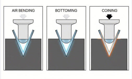
Air Bending vs Bottom Bending Explained
When you bend metal using air bending, the punch doesn't force the material fully into the die. Instead, contact occurs at only three points: the punch tip and both die shoulders. This creates what fabricators call a "floating" bend, where the final angle depends entirely on how deep the punch penetrates the V-opening.
According to Fab-Line Machinery, air bending sheet metal offers several distinct advantages:
- Lower tonnage requirements due to leverage effects
- One tooling set can produce multiple bend angles
- Reduced tooling costs and faster setup times
- Suitable for thicker materials that would exceed machine capacity with other methods
The tradeoff? Air bending produces slightly less consistent results because the angle depends on precise stroke depth control. High-quality CNC bending equipment compensates for this through advanced positioning systems.
Bottom bending, also called bottoming, takes sheet bending a step further. The punch forces the material until it contacts both the punch tip and the die's sidewalls. As Eurostamp Tooling explains, this technique emerged as an alternative to coining, allowing fabricators to work with thicker materials while achieving better accuracy than air bending.
During bottoming, the punch presses the sheet against the die bottom, causing controlled flexing. This additional contact creates a smaller internal bend radius and reduces springback, the tendency of bent metal to partially return toward its original shape.
When Coining Delivers Superior Results
Coining represents the most forceful approach to press bending. The term itself comes from coin manufacturing, where enormous pressure forces metal to conform precisely to die surfaces. During coining, the punch and die apply enough tonnage to actually thin the material slightly at the bend line.
This extreme force eliminates springback almost entirely. Your tooling angle becomes your final angle, period. Coining produces the most accurate, repeatable bends possible, making it ideal for precision applications where angular tolerance is critical.
However, coining requires significantly higher tonnage, often five to eight times more than air bending for the same material. This limits its practical application to thinner sheets, typically under 1.5 mm according to industry standards. The technique also demands matched punch and die angles for each bend specification.
Shape-Based Bending Categories
Beyond the three primary press brake techniques, fabricators categorize bends by their resulting geometry:
- V-bending: The most common form, creating angular bends using V-shaped punch and die combinations
- U-bending: Produces channel-shaped profiles with two parallel bends in a single operation
- Edge bending: Also called wipe bending, this technique bends only a portion of the sheet while clamping the rest flat
| Bending Method | Precision Level | Tooling Requirements | Material Suitability | Typical Applications |
|---|---|---|---|---|
| Air Bending | Moderate (±0.5°) | Single tooling set for multiple angles | All thicknesses, especially heavy gauge | General fabrication, structural components |
| Bottom Bending | Good (±0.25°) | Angle-specific tooling preferred | Light to medium gauge materials | Brackets, enclosures, precision parts |
| Coining | Excellent (±0.1°) | Exact-angle matched punch and die | Thin sheets under 1.5 mm | High-precision components, decorative work |
| Edge/Wipe Bending | Good | Specialized wipe dies and pressure pads | Thin to medium gauge | Panel edges, hemmed parts, roofing components |
Understanding these methods helps you communicate effectively with fabrication partners and make informed decisions about which approach suits your project. But the bending method is only part of the equation. How different materials respond during deformation significantly impacts your final results, which brings us to material-specific considerations.
Material Properties That Affect Bending Outcomes
Have you ever bent a paper clip back and forth until it snapped? That same principle applies to metal fabrication, but with far more precision and predictability. Every metal responds differently when force is applied, and understanding these behaviors is essential for achieving consistent, high-quality bends.
Three material properties fundamentally determine how metals behave during bending:
- Ductility: The metal's ability to deform without fracturing
- Tensile strength: The maximum stress a material can withstand while being stretched
- Work hardening: How much the metal strengthens (and becomes less ductile) as it's deformed
According to Inductaflex research, these properties vary significantly between common metals. Aluminum has an elastic modulus around 69-71 GPa, while steel measures approximately 200 GPa. This difference directly impacts how each material springs back after bending and what tooling adjustments fabricators must make.
How Aluminum Behaves Differently Than Steel
When bending aluminum sheet metal, you'll encounter challenges that don't exist with steel. Aluminum bending requires special attention because the material hardens quickly during forming and has a lower yield strength compared to most steels.
Here's what makes bending aluminium sheet unique:
- High springback tendency: Aluminum's lower stiffness causes it to spring back more aggressively than steel
- Surface sensitivity: Visible marks and scuffing occur more easily, requiring polished or coated dies
- Cracking risk in hardened tempers: T6 temper aluminum cracks more readily with tight bend radii
- Rapid work hardening: The material becomes less formable as deformation progresses
Steel bending presents different considerations. While it demands significantly higher tonnage due to greater strength, steel holds its shape more reliably after forming. Low-carbon steels exhibit minimal springback, though high-strength variants like DP980 (with yield strengths reaching 900 MPa) can show moderate recovery and accelerate tool wear.
Stainless steel bending combines challenges from both materials. It work hardens more aggressively than carbon steel, requiring careful attention to forming sequence and tooling selection. The material's higher tensile strength also demands greater press capacity.
Copper falls at the opposite end of the spectrum. Its high ductility allows tight bend radii without cracking, especially in annealed condition. However, copper thins under excessive pressure and requires low-friction dies to prevent surface damage.
Understanding Springback and Compensation Techniques
Springback is perhaps the most misunderstood phenomenon in metal bending fabrication. When you release forming pressure, the bent metal partially returns toward its original flat shape. This isn't a defect but rather a predictable material behavior that skilled fabricators compensate for during setup.
Why does springback happen? As Dahlstrom Roll Form explains, when metal bends, the inner region compresses while the outer region stretches. The compressive forces inside the bend are less than the tensile forces on the outside, creating an imbalance that makes the metal want to return to its original form.
The main predictors of springback are:
- Yield point: The stress level at which the metal stops reverting to its original shape
- Elastic modulus: How the material's stress changes with applied strain
- Material thickness: Thinner sheets typically exhibit greater springback
- Bend radius: Tighter radii generally reduce springback percentage
Knowing how to overcome springback is less about prevention and more about preparation. The primary compensation technique is overbending, where fabricators intentionally bend past the target angle, allowing springback to bring the part to the correct final dimension. CNC press brakes can automatically calculate and apply this compensation based on material type and thickness.
Material thickness and gauge directly influence both springback behavior and minimum achievable bend radii. As a general rule, thicker materials require larger inside bend radii to prevent cracking. For aluminum in hardened tempers, a radius equal to one or two times the material thickness typically prevents fracturing. Steel offers more flexibility, with acceptable radii depending on grade, rolling direction, and sheet thickness.
Understanding these material-specific behaviors helps you predict outcomes and communicate requirements clearly. But to truly optimize your designs, you'll need to understand how bend radius specifications translate into practical calculations.
Bend Radius Specifications and Calculations
Sounds technical? It doesn't have to be. The sheet metal bend radius is simply the measurement of the inside curve when you fold a piece of metal. Get this number wrong, and you'll end up with cracked parts, wasted material, or components that don't fit together. Get it right, and your fabrication runs smoothly from first prototype to final production.
The relationship between bend radius and material thickness follows a straightforward principle: tighter radii create more stress on the outer surface of the bend, increasing the risk of cracking. Larger radii spread this stress over a wider area but consume more material and may not fit your design constraints.
According to Xometry, a common rule of thumb for determining the steel plate minimum bend radius is based on sheet thickness and material type. Thicker sheets require larger bend radii because bending induces tensile and compressive stresses on the sheet. Thicker materials are less flexible and more prone to cracking if the bend radius is too small.
Calculating Your Minimum Bend Radius
When you're designing parts for bending, you need concrete numbers, not just general principles. The minimum bend radius depends on three primary factors:
- Material type: Ductile materials like mild steel and copper tolerate tighter bends than high-strength alloys or hardened aluminum
- Material thickness: Thicker sheets demand proportionally larger radii to prevent fracturing
- Grain direction: Bending perpendicular to the rolling direction allows tighter radii than bending parallel to it
For practical guidance, refer to a sheet metal bend radius chart based on your specific material. The table below summarizes recommended minimum bend radii for common materials:
| Material | Minimum Inside Bend Radius | Notes |
|---|---|---|
| Mild Steel | 0.5 × material thickness | Most forgiving for tight bends |
| Stainless Steel (304) | 0.5-1.0 × material thickness | Work hardening increases cracking risk |
| Aluminum (soft tempers) | 1.0 × material thickness | Annealed conditions allow tighter radii |
| Aluminum (T6 temper) | 2.0-3.0 × material thickness | Hardened tempers require larger radii |
| Copper (annealed) | 0.25-0.5 × material thickness | High ductility allows tight forming |
These values represent starting points. Services like SendCutSend provide specific bend radius guidelines for their equipment. When using the sendcutsend bend radius recommendations, you can preview your bends in a 3D model during checkout to verify angles and flange orientations before production.
Why Grain Direction Changes Everything
Here's something many designers overlook: metal sheets aren't uniform in all directions. During manufacturing, the rolling process aligns the metal's grain structure along the rolling direction. This creates directional properties that significantly affect bending outcomes.
When you bend perpendicular to the grain (across the rolling direction), the metal fibers stretch more evenly, allowing tighter radii without cracking. Bending parallel to the grain forces the material to stretch along already-aligned fibers, which concentrates stress and increases fracture risk.
For critical applications, specify bend orientation relative to grain direction in your drawings. As a general guideline:
- Bending perpendicular to grain allows radii up to 30% tighter than parallel bending
- When grain direction is unknown, use the more conservative (larger) radius recommendation
- For parts requiring multiple bends at different orientations, position the most critical bend perpendicular to grain
Bending Formulas for Flat Pattern Development
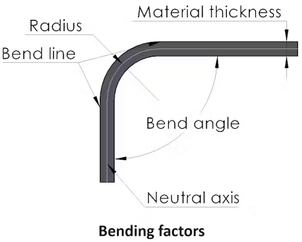
Understanding the bending formula for sheet metal helps you accurately predict the flat pattern dimensions needed to achieve your desired bent shape. Two calculations matter most: bend allowance and bend deduction.
According to Xometry's design guide, bend allowance represents the arc length along the neutral axis, the imaginary line within the material thickness that neither stretches nor compresses during bending. The formula is:
BA = A × (π / 180) × (R + K × T)
Where A is the bend angle in degrees, R is the inside bend radius, K is the K-factor (typically 0.3-0.5 depending on material and method), and T is material thickness.
The K-factor varies based on material properties, bend radius relative to thickness, and bending method. For air bending with a radius greater than material thickness, a K-factor of 0.4-0.5 works for most materials. Coining and bottom bending typically use lower values around 0.3-0.4.
Bend deduction tells you how much to subtract from your total flange lengths to get the correct flat pattern. This matters because the material effectively "grows" during bending as the outer fibers stretch.
For practical application, most CAD software and fabrication services calculate these values automatically. However, understanding the underlying concepts helps you troubleshoot when parts don't fit as expected or when you need to adjust designs for different materials.
The bend radius for sheet metal affects far more than just whether your part cracks. It influences springback compensation, tooling selection, and even your minimum flange lengths. With these calculations in hand, you're ready to apply them through proper design guidelines that ensure your parts bend successfully the first time.
Design Guidelines for Bendable Parts
You've selected your material and calculated your bend radius. Now comes the critical question: will your part actually work when it hits the press brake? The gap between a CAD model and a manufacturable component often comes down to sheet metal design guidelines that account for real-world forming limitations.
When working with sheet metal, your design decisions directly impact three outcomes: whether the part can be made at all, how much it costs, and whether quality meets specifications. According to Norck's DFM guidelines, ignoring the physical limits of metal leads to higher prices, longer wait times, and a higher risk of errors.
Designing Parts That Bend Successfully
Think of a press brake's tooling like giant fingers trying to grip and fold your part. If certain features are too small, too close together, or positioned incorrectly, those fingers simply can't do their job. Here are the critical design parameters that determine success:
Minimum Flange Length
The flange is the portion of metal being bent upward. Your equipment needs enough surface area to actually grip and fold the material. As Norck explains, trying to bend a flange that's too short is like trying to fold a tiny sliver of paper with giant fingers.
The simple rule? Make sure your flange is at least four times as long as the material thickness. For 2mm steel, that means a minimum 8mm flange. Shorter flanges require custom, expensive tooling that can double your production costs.
Hole-to-Bend Distance
Place a hole too close to a bend line, and you'll watch it stretch into an oval during forming. That deformed hole won't accept screws or pins properly, creating assembly failures down the line.
According to Five Flute's design guide, holes should be located approximately 2.5 times material thickness plus one bend radius away from bends. For a 1.5mm sheet with a 2mm bend radius, that means positioning holes at least 5.75mm from the bend line.
Relief Notches and Their Purpose
When you bend metal alongside a flat edge, the material tries to separate at the corner. This creates stress concentrations that lead to tearing or cracking. The solution? Cut a small notch, called a bend relief, at the end of your bend lines.
The bypass notches sheet metal forming purpose is straightforward: they prevent crack propagation and allow controlled deformation where the curved bend meets flat material. Aim for a relief width greater than or equal to half the material thickness, with a length that extends just past the bend line.
Common Design Mistakes That Increase Costs
Some design choices seem reasonable on screen but create manufacturing nightmares. Avoiding these common errors keeps your projects on budget:
- Inconsistent bend radii: Designing all bends with the same radius allows fabricators to use one tool for every fold, saving setup time and labor costs
- Ignoring grain direction: Parts that bend with the material's rolling grain are more likely to crack months after delivery
- Overly tight tolerances: Being too strict where it isn't necessary increases inspection time. Standard sheet metal folding tolerances keep projects on budget
- Non-standard hole sizes: Custom dimensions require specialized tooling. Use off-the-shelf sizes like 5mm, 6mm, or standard fractional dimensions
- Narrow features near heat zones: Laser-cut slots or fingers that are too thin can warp from cutting heat, creating Pringle-like distortion
According to Norck's research, keeping narrow cutouts at least 1.5 times wider than the material thickness prevents heat-related warping.
Bend Sequence Planning
Complex parts with multiple bends require careful sequencing. Each bend changes the part's geometry, potentially creating interference with the press brake's tooling or backgauge. Design your part with the forming sequence in mind:
- Inside bends typically must be formed before outside bends
- Short flanges may become inaccessible after adjacent bends are formed
- Parts with bends in multiple planes require careful collision analysis
Many tools for forming sheet metal include software that simulates bend sequences, identifying potential collisions before production begins.
Design Checklist for Bendable Parts
Before submitting your design for fabrication, verify these critical parameters:
- Minimum inside bend radius equals or exceeds material thickness (or material-specific recommendations)
- All flanges measure at least 4× material thickness
- Holes are positioned 2.5× thickness plus bend radius from bend lines
- Bend reliefs are included where bends meet flat edges
- All bend radii are consistent where possible
- Grain direction is specified for critical bends
- Hole and slot dimensions use standard sizes
- Narrow features maintain 1.5× thickness minimum width
- Bend sequence has been verified for tooling clearance
Following these sheet metal design guidelines transforms your concepts into manufacturable parts that meet quality standards on the first production run. With your design optimized for bending, the next consideration is matching your requirements to the right equipment capabilities.
Bending Equipment and Capability Considerations
Ever watched a craftsman hand-fold a metal bracket with a simple lever-operated brake? Now imagine a computer-controlled machine executing the same bend with micron-level precision, automatically compensating for material variations. Both approaches have their place in modern fabrication, and understanding when to use each can significantly impact your project's cost, quality, and timeline.
The world of sheet metal bending equipment spans from basic hand brakes costing a few hundred dollars to sophisticated CNC systems exceeding half a million. Your choice depends on production volume, precision requirements, part complexity, and budget constraints. Let's break down how to use a sheet metal brake effectively and which type matches your specific needs.
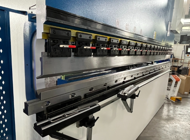
CNC Press Brakes vs Manual Equipment
The fundamental difference between CNC and manual press brakes comes down to control. Both apply force through a punch and die to bend sheet metal, but how that force and positioning are managed creates dramatically different outcomes.
A manual press brake relies entirely on operator skill. According to Emin Academy's research, these machines use physical limit stops and mechanical linkages, with hand-operated adjustments and analog readouts. The operator must "feel" the material's resistance and visually estimate springback. Each bend requires testing, adjusting, and rechecking until the correct angle is achieved.
Manual equipment offers distinct advantages for certain applications:
- Lower upfront cost (typically 2-4 times less than CNC equivalents)
- Simple maintenance with fewer electronic components
- No programming required for quick, one-off jobs
- Excellent for training and educational environments
A CNC press brake transforms this process through computerized control. Operators program desired dimensions, and the machine automatically executes precise, repeatable bends. Linear encoders continuously measure ram position and correct deviations in real time, achieving angular tolerances of ±0.1° compared to ±0.5° or worse with manual methods.
The metal steel bending machine equipped with CNC capabilities can import CAD files directly, simulate bending sequences in 3D before production, and even suggest optimal tooling based on part geometry. This eliminates trial bends and dramatically reduces setup time.
For high-volume production, CNC technology can increase output by 200-300% compared to manual methods. The steel bending equipment pays for itself through reduced labor, minimized waste, and consistent quality across thousands of parts.
| Equipment Type | Precision | Speed | Setup Time | Ideal Applications |
|---|---|---|---|---|
| Manual Hand Brake | ±1-2° | Slow (operator-dependent) | Quick for simple bends | Prototypes, one-off repairs, light gauge work |
| Manual Hydraulic Press Brake | ±0.5° | Moderate | 30-60 minutes per setup | Small batches, general fabrication, training |
| CNC Sheet Metal Brake | ±0.1° | Fast (automated cycles) | 5-15 minutes (programmed) | Production runs, complex multi-bend parts |
| CNC with Robotic Loading | ±0.1° | Very Fast (24/7 operation) | Initial programming only | High-volume automotive, appliance manufacturing |
How to Determine Required Tonnage
Tonnage is the force your metal sheet bending machine must deliver to complete a bend. Underestimate this requirement, and you'll damage equipment or produce incomplete bends. Overspecify, and you'll pay for capacity you don't need.
Material thickness and bend length are the primary factors determining tonnage requirements. According to The Fabricator, calculating safe operating limits involves four key considerations:
1. Air Bending Tonnage Formula
For air bending, which is the most common method, tonnage increases with material thickness and decreases with larger die openings. A typical calculation for mild steel uses:
Tonnage per foot = (575 × Material Thickness²) ÷ Die Opening Width
For example, bending 3mm mild steel with a 24mm die opening requires approximately (575 × 9) ÷ 24 = 216 tons per meter of bend length.
2. Centerline Load Limits
Press brakes are designed for centerline loading, meaning full tonnage should be applied over approximately 60% of the bed length, centered on the machine. A 100-ton brake with a 3-meter bed can safely apply those 100 tons over 1.8 meters at center.
Exceeding this centerline load limit causes permanent deflection damage to the ram and bed. The Fabricator notes that the maximum tonnage per inch equals machine rating divided by (bed length in inches × 0.60).
3. Tool Load Limits
Your tooling has its own tonnage ceiling independent of machine capacity. Precision-ground tools rated around 70 HRC can handle higher loads but will throw shrapnel if overloaded. Older planed-style tools (30-40 HRC) bend and break more predictably but fail at lower tonnages.
4. Sinking Tonnage Limits
This refers to the force required to physically embed tooling into the press brake's bed or ram. Larger tool shoulder widths increase land area and allow greater tonnage before deformation occurs.
Bed Length and Maximum Part Size
The bed length of your metal bending equipment directly limits the longest bend you can make in a single operation. But it's not a simple one-to-one relationship.
When bending parts shorter than the bed length, you can work off-center, but this requires careful tonnage distribution to avoid uneven loading. According to Hunsone, the backstop system also affects positioning accuracy. Manual backstops are simple and cost-effective, while servo-driven backstops offer higher precision for parts requiring exact positioning.
Consider these bed length factors when selecting equipment:
- Parts requiring bends near both ends may need a bed 20-30% longer than the part
- Multiple shorter parts can sometimes be bent simultaneously to maximize efficiency
- Longer beds generally mean higher machine cost and floor space requirements
- Segmented tooling allows partial-bed setups for smaller parts without repositioning
For shops handling varied work, a cnc sheet metal brake with 3-4 meters of bed length provides versatility for most applications. Specialized operations bending longer structural components may require 6-meter or longer beds.
Modern CNC systems address capability gaps through automation features like automatic tool clamping, memory-based setup recognition, and robotic material handling. These additions further reduce the skill gap between operators and enable consistent quality even during multi-shift operations.
Selecting the right equipment matters, but equally important is understanding how to verify that your bends meet specifications. This brings us to precision tolerances and the quality standards that define acceptable outcomes.
Precision Tolerances and Quality Standards
When your bent part arrives, how do you know it's actually correct? A bracket might look perfect to the naked eye yet fail during assembly because it's half a degree off specification. Understanding precision tolerances transforms vague expectations into measurable outcomes that you can verify, communicate, and enforce.
In metal bending fabrication, tolerance refers to the acceptable variation from your specified dimensions. These aren't arbitrary numbers. They represent the practical limits of manufacturing processes, material behaviors, and economic feasibility. According to Komacut's tolerance guide, understanding process-specific tolerances helps you select the right method that meets your part's requirements while avoiding unnecessarily tight specifications that drive up costs.
What Tolerance Specifications Actually Mean
Two tolerance categories matter most in precision bending and precision metal bending applications: angular tolerances and dimensional tolerances. Each serves a distinct purpose in defining part quality.
Angular Tolerances
Angular tolerance controls the allowable deviation from your specified bend angle. When you specify a 90° bend with ±0.5° tolerance, you're accepting parts ranging from 89.5° to 90.5°. This seemingly small range has real consequences during assembly.
According to Accurl's research, properly maintained press brakes typically achieve an average tolerance of ±0.5° in bend angle. Under optimal conditions with advanced CNC technology, high-quality tooling, and stable material properties, tolerances can reach as tight as ±0.1-0.2°. High-end press brakes equipped with dynamic crowning, real-time feedback systems, and laser angle measurements can maintain bend angle accuracy below ±0.1° under ideal conditions.
Dimensional Tolerances
Dimensional tolerances govern variations in overall part size, including length, width, and the precise location of bends and features. These specifications ensure components fit together during assembly without gaps or interference.
Standard sheet metal bending services typically achieve:
- Standard XYZ tolerances: ±0.45 mm for general fabrication work
- High precision tolerances: ±0.20 mm for demanding applications
- Linear positioning: ±0.1-0.2 mm when properly calibrated
CNC press brakes demonstrate exceptional positioning accuracy, often within a few thousandths of an inch (0.001"-0.004"). This precision enables repeatable production across thousands of parts with minimal variation.
Tolerance Grades and Their Applications
Not every part requires aerospace-level precision. Matching tolerance requirements to actual functional needs keeps projects cost-effective while ensuring performance. Here's how different tolerance grades typically apply:
- Coarse tolerances (±1° angular, ±1.0 mm dimensional): Structural brackets, non-critical enclosures, agricultural equipment where fit is important but not critical
- Standard tolerances (±0.5° angular, ±0.45 mm dimensional): General fabrication, HVAC components, electrical enclosures, most commercial applications
- Precision tolerances (±0.25° angular, ±0.20 mm dimensional): Automotive components, medical device housings, assemblies with multiple mating parts
- High precision tolerances (±0.1° angular, ±0.10 mm dimensional): Aerospace components, precision instruments, applications where failure has serious consequences
Factors That Affect Bend Accuracy
Achieving consistent tolerances isn't automatic. Multiple variables influence whether your parts meet specifications, and understanding these factors helps you evaluate metal bending services and troubleshoot quality issues.
Equipment Calibration
A press brake is only as accurate as its calibration. According to Accurl's analysis, even slight frame tilts of 0.1° can lead to significant variations in force uniformity, impacting bending accuracy by as much as ±0.5°. The flatness of the press brake bed directly affects workpiece straightness. A deviation of just 0.06 mm in the table can result in a 0.17° error in a 90° bend.
Key calibration factors include:
- Ram and frame alignment verification
- Back gauge positioning accuracy at multiple reference points
- Hydraulic system pressure consistency
- Crowning system adjustment for bed deflection compensation
Manufacturers recommend monthly or quarterly calibration checks depending on production volume and precision requirements.
Tooling Condition
Your punch and die are the direct interface with the material. Worn tooling produces inconsistent results regardless of machine precision. Even minor imperfections like tiny chips or rounding at die edges can lead to noticeable angle deviations.
Regular tooling maintenance includes:
- Inspecting tool edges for wear, chips, or damage
- Measuring punch tip radius after extensive production runs
- Verifying die opening dimensions with feeler gauges or micrometers
- Regrinding or replacing worn tools before quality degrades
Material Consistency
The metal itself introduces variability. Thickness variations as slight as 0.1 mm significantly affect springback and final bend angles. Komacut notes that sheet metal has built-in variation. There's a difference between sheets produced in the same batch and even thickness differences between portions of the same sheet.
Material factors affecting accuracy include:
- Thickness tolerance from the mill (varies by material type and rolling process)
- Hardness variations within and between batches
- Flatness deviations that cause uneven die contact
- Grain direction relative to bend orientation
For high-precision work, testing sample coupons from each material batch allows operators to adjust machine settings based on actual material behavior.
Operator Skill
Even with CNC automation, human expertise remains critical. Skilled operators understand material behaviors, machine idiosyncrasies, and the nuances of different bending techniques. They quickly identify and correct deviations, adjusting parameters like ram depth or back gauge position to avoid errors.
Inexperienced operators may miss subtle alignment issues or necessary adjustments, potentially leading to defects across production runs. Mentoring programs and documented setup procedures help bridge this knowledge gap.
Quality Control Methods for Verifying Bend Accuracy
Trust but verify. Reliable sheet metal bending near me providers employ multiple quality control methods to ensure parts meet specifications:
- Digital angle gauges: Measure actual bend angles to within 0.1° accuracy
- Coordinate measuring machines (CMMs): Verify dimensional accuracy across complex geometries
- Go/no-go gauges: Quick verification that parts fall within tolerance bands
- First article inspection: Detailed measurement of initial parts before production proceeds
- Statistical process control (SPC): Tracking measurements across production runs to identify drift before parts fail specifications
Advanced press brakes incorporate real-time angle measurement systems that automatically pause operations if bend deviation exceeds predefined thresholds, enabling immediate correction.
Industry Standards and Certifications
For applications where quality is non-negotiable, industry certifications provide assurance that fabricators maintain rigorous process controls. IATF 16949 certification, specifically designed for the automotive supply chain, requires documented quality management systems, statistical process control, and continuous improvement practices.
This certification matters because automotive components often demand tight tolerances combined with high-volume production consistency. A certified fabricator has demonstrated their ability to maintain precision across thousands or millions of parts while tracking and addressing any deviations.
Other relevant standards include ISO 9001 for general quality management and AS9100 for aerospace applications, each specifying documentation, traceability, and measurement requirements appropriate to their industries.
Understanding these precision requirements helps you specify appropriate tolerances and evaluate whether potential fabrication partners can actually deliver. With quality expectations clearly defined, the next step is learning how to select and work with the right service provider for your specific needs.
Selecting the Right Bending Service Provider
You've designed your part, calculated your bend radii, and specified your tolerances. Now comes a decision that can make or break your project: choosing where to have it made. Whether you're searching for metal bending near me or evaluating global suppliers, the selection process follows the same fundamental principles.
Finding qualified metal bending services near me isn't just about proximity. According to G.E. Mathis Company, it's important to select a service provider with extensive experience, preferably in your industry, as well as the capabilities, quality assurance practices, equipment, scalable capacity, certifications, and reliable customer support necessary for your project. The right partner delivers consistent quality, communicates proactively, and helps you optimize designs before production begins.
Preparing for Your First Quote Request
The accuracy of your fabrication quote depends entirely on the information you provide. Incomplete requests lead to price swings, delays, and frustrating back-and-forth communication. According to LTJ Industrial's 2026 fabrication guide, a well-prepared drawing ensures your quote reflects your true requirements, minimizing the risk of costly revisions later.
Before contacting metal bending shops, gather this essential information:
- Material specifications: Include alloy or grade (such as 304 stainless or 6061 aluminum), thickness, and any required certifications
- Quantity requirements: Specify initial order size, expected annual volumes, and whether you need prototype quantities first
- Tolerance needs: Define angular and dimensional tolerances based on functional requirements, not arbitrary precision
- Delivery timelines: Communicate firm deadlines, preferred lead times, and whether you can accommodate phased deliveries
- Finish requirements: Specify surface treatments like powder coating, anodizing, or raw mill finish
- Special requirements: Note any assembly steps, inspection documentation, or industry-specific compliance needs
For technical documentation, CAD drawings are the gold standard for custom metal bending projects. These digital files allow fabricators to analyze every aspect of your design, ensuring precise pricing and manufacturability. If CAD isn't available, detailed hand sketches or annotated PDFs with clear dimensions can suffice, but always aim for clarity.
Quote Request Preparation Checklist
- Complete CAD files or detailed dimensioned drawings
- Material type, grade, and thickness clearly specified
- Quantity breakdown (prototype, initial production, annual forecast)
- Tolerance specifications for critical dimensions and angles
- Surface finish requirements documented
- Delivery timeline and shipping destination identified
- Special certifications or documentation requirements listed
- Contact information for technical questions
Companies offering comprehensive services often provide rapid quote turnaround. For example, Shaoyi (Ningbo) Metal Technology delivers 12-hour quote responses, allowing you to compare options quickly without waiting days for pricing feedback.
Evaluating Fabrication Partners
Once you've gathered your documentation, it's time to assess potential providers. As Atscott MFG explains, while a low price may catch your eye, true value lies in the fabricator's capabilities, reliability, and ability to meet your project requirements from start to finish.
When evaluating sheet metal benders near me or remote suppliers, consider these critical factors:
Equipment Capabilities
Ensure the shop has the necessary equipment for your specific requirements. For cnc bending services, verify their press brake tonnage, bed length, and accuracy specifications. Ask about:
- Maximum material thickness and bend length capacity
- CNC versus manual equipment for your precision requirements
- Tooling inventory for your specified bend radii
- Auxiliary capabilities like laser cutting, welding, or finishing
Certifications and Quality Systems
Industry certifications demonstrate commitment to consistent quality. For steel bending and fabrication in regulated industries, look for:
- ISO 9001 for general quality management systems
- IATF 16949 for automotive supply chain requirements
- AS9100 for aerospace applications
- AWS certifications for welded assemblies
These certifications require documented processes, inspection protocols, and continuous improvement practices that translate to reliable production quality.
Experience and Expertise
Industry-specific experience matters significantly. Fabricators familiar with your sector anticipate unique challenges and understand applicable standards. Ask for examples of completed projects similar to yours and verify their ability to handle your specific materials and geometries.
DFM Support and Prototyping
The best fabrication partners help optimize your designs before production begins. Design for manufacturability (DFM) support identifies potential issues like insufficient flange lengths or problematic hole placements while changes are still inexpensive to implement.
Rapid prototyping capabilities bridge the gap between design and production validation. Providers like Shaoyi offer 5-day rapid prototyping alongside comprehensive DFM support, allowing you to test physical parts and refine designs before committing to production tooling. This approach reduces costly iterations and accelerates your overall timeline.
Communication and Responsiveness
Evaluate how quickly and clearly potential partners respond to your initial inquiry. Reliable fabricators provide timely updates, clarify ambiguities, and offer proactive support during both quoting and production. A partner who prioritizes open communication helps prevent costly misunderstandings.
Red Flags to Watch For
According to LTJ Industrial's research, remain vigilant for warning signs that a quote may not be reliable:
- Vague or incomplete line item breakdowns
- Unusually low prices with unclear scope
- Missing delivery or warranty terms
- No references or case studies available
- Slow or unclear communication during the quoting process
If you encounter any of these issues, proceed with caution. Thoroughly vetting each partner ensures your project meets quality, cost, and delivery expectations.
With your service provider selected and project specifications clearly documented, you're positioned for successful production. The final step is understanding how to apply everything you've learned to move your project forward efficiently.
Putting Metal Bending Knowledge Into Action
You've journeyed from basic definitions to advanced tolerance specifications. Now it's time to transform that knowledge into successful projects. Whether you're learning how to bend sheet metal for the first time or refining an established production process, the principles remain consistent: success depends on aligning material properties, design parameters, equipment capabilities, and fabrication expertise.
The most successful metal bending projects start with design optimization and partner collaboration, not just equipment selection. Getting the fundamentals right before production begins eliminates costly revisions and ensures parts meet specifications on the first run.
Understanding how to bend a metal effectively means recognizing that each decision, from material grade to bend radius to tolerance specification, creates a chain reaction through your entire project. Skip a step, and problems compound. Get the sequence right, and production flows smoothly from prototype to final delivery.
Your Metal Bending Project Roadmap
Regardless of your experience level, follow this sequential approach to maximize your chances of success:
- Define functional requirements first: Determine what tolerances your application actually needs rather than specifying arbitrary precision that inflates costs
- Select materials based on formability and function: Balance mechanical requirements with bending behavior, considering springback, minimum bend radii, and grain direction
- Design for manufacturability: Apply the guidelines covered earlier, including minimum flange lengths, hole-to-bend distances, and relief notches where needed
- Match equipment to requirements: Ensure your fabrication partner has appropriate tonnage, bed length, and precision capabilities for your specific parts
- Validate before production: Use prototyping to confirm designs work in practice, not just on screen
For engineers new to metal benders and bending processes, start with simpler geometries and standard materials before tackling complex multi-bend assemblies. For experienced professionals, the roadmap serves as a quality checkpoint to ensure no critical steps are overlooked during project planning.
Taking the Next Step
Armed with this comprehensive understanding, you're ready to move from theory to action. Your next steps depend on where you are in your project lifecycle:
- Early design phase: Apply DFM principles now while changes are inexpensive. Consult with potential fabrication partners before finalizing drawings
- Ready to prototype: Prepare complete documentation and seek partners offering rapid turnaround to validate designs quickly
- Scaling to production: Verify equipment capabilities, certifications, and quality systems match your volume and precision requirements
For automotive applications requiring chassis, suspension, or structural components, partnering with an IATF 16949-certified manufacturer ensures your sheet metal bender meets the rigorous quality standards the industry demands. Shaoyi (Ningbo) Metal Technology combines 5-day rapid prototyping with comprehensive DFM support, helping you optimize designs before committing to production tooling. Their 12-hour quote turnaround removes the typical waiting game from supplier evaluation, letting you compare options and make informed decisions faster.
The journey from raw sheet to precision part doesn't have to be complicated. With the right knowledge, preparation, and fabrication partner, your metal bending projects can consistently deliver the quality, cost-efficiency, and timeline performance your applications require.
Frequently Asked Questions About Metal Bending Fabrication
1. What is the bending process in fabrication?
Bending in fabrication is the controlled application of force to deform metal sheets or plates along a straight axis, creating permanent angular or curved shapes. Using equipment like press brakes, the process applies pressure through a punch and die system, causing the metal's outer fibers to stretch while inner fibers compress. This plastic deformation exceeds the material's yield strength without breaking it, resulting in precise angles ranging from simple L-brackets to complex multi-bend enclosures. Common techniques include air bending, bottom bending, and coining, each offering different precision levels and tonnage requirements.
2. How much does it cost to bend metal?
Metal bending costs vary based on material type, thickness, complexity, and quantity. For mild steel parts, costs typically range from $3 to $10 per part for standard bending operations. Factors affecting price include material grade (stainless steel and specialty alloys cost more), number of bends per part, tolerance requirements, and setup time. CNC bending services may charge $70-$130 per hour for custom work. To optimize costs, use consistent bend radii across your design, specify only necessary tolerances, and consolidate orders to reduce setup charges. Requesting quotes with complete documentation helps ensure accurate pricing.
3. What materials can be bent in metal fabrication?
Most ductile metals can be bent successfully, including mild steel, stainless steel, aluminum, copper, brass, and titanium. Each material behaves differently during bending. Mild steel is the most forgiving, allowing tight bend radii with minimal springback. Aluminum requires larger radii in hardened tempers (T6) but bends easily when annealed. Stainless steel work hardens quickly, demanding careful attention to forming sequence. Copper offers excellent ductility for tight bends. The key is matching bend radius specifications to material properties, considering factors like grain direction, thickness, and temper to prevent cracking.
4. What is the difference between CNC and manual press brakes?
CNC press brakes use computerized control for automated, programmable bending with angular tolerances of ±0.1°, while manual press brakes rely on operator skill and physical limit stops, achieving ±0.5° or less accuracy. CNC machines import CAD files directly, simulate bend sequences, and automatically compensate for springback, reducing setup time to 5-15 minutes versus 30-60 minutes for manual equipment. Manual brakes cost 2-4 times less upfront and work well for simple, one-off jobs. CNC technology increases output by 200-300% and delivers consistent quality across high-volume production runs.
5. How do you prevent cracking when bending metal?
Preventing cracks during metal bending requires attention to bend radius, material condition, and grain orientation. Use minimum bend radii appropriate for your material—typically 0.5× thickness for mild steel and 2-3× thickness for hardened aluminum. Always bend perpendicular to the grain direction when possible, as this allows radii up to 30% tighter than parallel bending. For hardened materials, consider annealing before forming. Include bend relief notches where bends meet flat edges to prevent stress concentration. Additionally, ensure material thickness is consistent and avoid bending at temperatures below manufacturer recommendations for cold-sensitive alloys.