 Small batches, high standards. Our rapid prototyping service makes validation faster and easier —

A Guide to Leak Testing for Die Cast Housings

TL;DR
Leak testing for die cast housings is a critical quality control process designed to detect microscopic defects like porosity and cracks before assembly. This preventative step is essential for ensuring component integrity and product reliability. The most widely used and highly accurate method is pressure decay testing, which uses pressurized air to identify leaks and prevent costly downstream failures in manufacturing.
The Importance of Leak Testing in Die Casting
In manufacturing, especially within the automotive and industrial sectors, the integrity of every component is paramount. Die cast parts, such as engine blocks, transmission housings, and electronic enclosures, form the backbone of countless complex assemblies. However, the die casting process itself can introduce vulnerabilities. Leak testing is a non-destructive quality assurance procedure that verifies the integrity of these components by identifying defects that could compromise their function. Detecting these issues early, before more value is added through machining or assembly, is a cornerstone of efficient and cost-effective production.
Die cast metals, particularly aluminum, are susceptible to defects like porosity, cracks, and other imperfections that can create leak paths. Porosity refers to microscopic voids or holes within the metal, a natural byproduct of the casting process that can allow fluids or gases to escape. Hot tears or cracks can also develop as the casting cools. Without rigorous testing, these flaws can lead to catastrophic failures in the final product, such as oil leaks in an engine, coolant loss in an EV battery housing, or moisture ingress that damages sensitive electronics. By identifying these potential failures on the production line, manufacturers can avoid expensive warranty claims, product recalls, and damage to their brand's reputation.
The business case for implementing a robust leak testing protocol is clear. It directly improves process efficiency by catching defective parts early, reducing scrap rates, and preventing bottlenecks in machining and assembly lines. Furthermore, the data gathered from leak testing can be used to refine the casting process itself, helping to identify and correct the root causes of porosity. As industries move towards more complex and high-performance designs, such as in electric vehicles where housings must protect sensitive electronics from water ingress, the demand for verified, leak-proof components has never been higher. Ensuring component quality is a shared responsibility across the supply chain, with suppliers of high-integrity metal parts playing a crucial role. For instance, companies that provide precision-engineered automotive forging parts contribute to a more reliable end product by focusing on material strength and defect-free manufacturing from the start.
Common Methods for Leak Testing Die Castings
Selecting the appropriate leak testing method is crucial and depends on factors like the part's size, the required sensitivity (reject leak rate), and production cycle time. Several proven techniques are used in the industry, each with distinct advantages for different applications. These methods are designed to provide reliable, repeatable, and measurable results to ensure every component meets stringent quality standards.
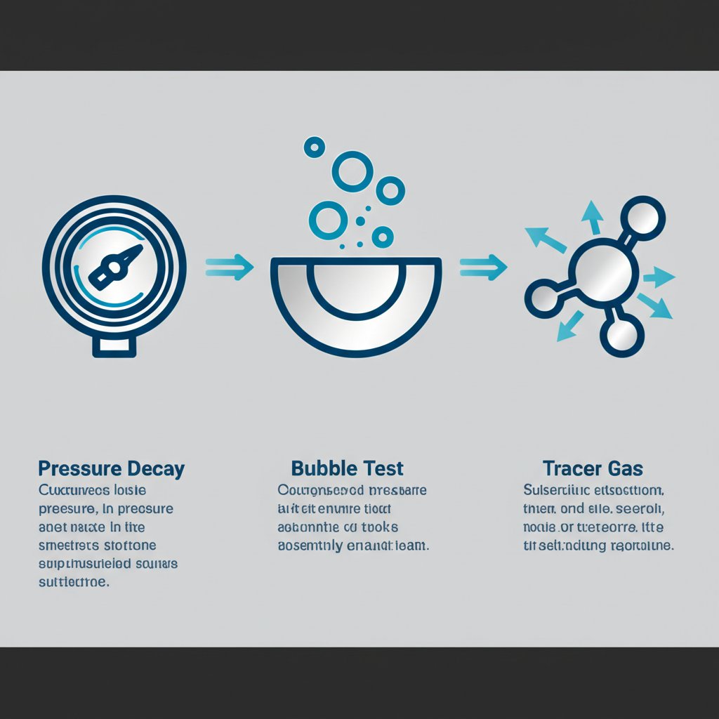
The three most prevalent methods for testing die cast housings are Pressure Decay, Bubble Leak Testing, and Tracer Gas Detection. Each operates on a different principle to identify leaks, from simple visual confirmation to highly sensitive gas analysis.
Pressure Decay Testing
Pressure decay is the most common and widely trusted method for testing die cast components. The process is straightforward yet highly effective: the part is sealed, filled with air to a specific target pressure, and then isolated from the air source. A highly sensitive pressure transducer then monitors the internal pressure over a set period. Any drop in pressure indicates that air is escaping through a leak path. This pressure change can be converted into a volumetric leak rate (e.g., standard cubic centimeters per minute or sccm) to determine if the part passes or fails. Its popularity stems from its accuracy, ease of automation, and the quantitative results it provides, making it ideal for high-volume production lines. A variation, vacuum decay, uses the same principle but applies a vacuum instead of positive pressure.
Bubble Leak Testing
The bubble leak test is the simplest and most intuitive method. In this process, the part is charged with compressed air and then submerged in a water tank. If a leak is present, a stream of bubbles will visibly escape from the defect's location, providing an immediate and clear indication of the leak's existence and location. While inexpensive and easy to perform, this method is highly dependent on operator observation and is less sensitive than other techniques. It is often used for less critical applications or as a preliminary diagnostic tool.
Tracer Gas Leak Detection
For applications requiring the highest sensitivity, tracer gas leak detection is the preferred method. This technique involves using a gas, typically helium, that has very small molecules capable of penetrating microscopic leak paths that air might not. In one common setup, the part is placed in a sealed chamber, which is then filled with a helium mixture. A vacuum is pulled on the inside of the part, and a detector measures if any helium molecules migrate from the chamber into the part. This method is exceptionally accurate for detecting porosity and is not affected by temperature or part volume changes, unlike air-based tests. It is essential for critical components in automotive and aerospace, such as advanced transmission housings with extremely low leak rate requirements.
| Method | Accuracy | Speed | Best For |
|---|---|---|---|
| Pressure Decay | High | Very Fast | Automated, high-volume production with defined leak rates. |
| Bubble Leak Test | Low to Medium | Slow | Locating leaks visually; less critical applications. |
| Tracer Gas (Helium) | Very High | Fast | Detecting microscopic porosity and very small leaks in critical components. |
Troubleshooting: Common Causes of Leak Test Failures
When a die cast housing fails a leak test, it is essential to diagnose the root cause efficiently to minimize production downtime and scrap. Failures can generally be attributed to one of three categories: material defects inherent to the casting, damage induced during processing, or errors in the testing procedure itself. A systematic approach to troubleshooting can quickly isolate the problem and lead to a sustainable solution.
The most common material defect is abnormal porosity. While a certain level of microscopic porosity is expected in die castings, larger or interconnected pockets can form leak paths. These are often caused by issues in the casting process, such as trapped gases or shrinkage during cooling. Similarly, cracks or hot tears can form in the material as it solidifies. These types of defects require adjustments to the die casting parameters, such as injection pressure, temperature, or die design, to resolve.
Even a perfectly cast part can fail if it is damaged during subsequent handling and machining. Dropping parts, stacking them incorrectly, or improper clamping during CNC machining can introduce cracks or deform sealing surfaces. These handling-induced failures underscore the importance of proper procedures throughout the entire manufacturing workflow, not just during casting. A thorough visual inspection of failed parts can often reveal scratches, dents, or other signs of physical damage that point to a handling issue.
Finally, the test itself can be the source of the failure. These are often termed "false failures" and can be particularly frustrating as they result in scrapping good parts. Common causes include an improper seal between the test fixture and the part, incorrect test parameters (e.g., pressure or time), or environmental factors like temperature fluctuations. A part that is still warm from a washing cycle can cause the air inside it to cool during the test, creating a pressure drop that mimics a leak. Establishing a stable, repeatable test environment and regularly verifying the test setup with a calibrated leak standard are critical to avoiding these costly errors.

Understanding Leak Testing Standards and Best Practices
To ensure consistency, accuracy, and reliability in leak testing, manufacturers adhere to established industry standards and best practices. These guidelines provide a framework for performing repeatable tests and calibrating equipment, which is essential for maintaining quality control across different production lines and facilities. Understanding these principles helps organizations build robust and trustworthy testing processes.
A key concept in this field is the "leak standard." This is not a document, but a physical device—a calibrated, simulated leak used to verify that air leak testing equipment is functioning correctly. By testing the system with a known leak rate, operators can ensure their measurements are accurate and reliable. This calibration process is a fundamental best practice for any quantitative leak test method like pressure decay or mass flow.
While there isn't one single, universal standard for all die cast leak testing, various standards bodies like ASTM (American Society for Testing and Materials) and ASME (American Society of Mechanical Engineers) publish standards for leak testing in specific contexts. For example, the SERP mentions ASME B31.3 for piping and ASTM F2338 for sealed packages. Although not directly for die castings, they illustrate how standardized procedures are developed to ensure safety and performance in different industries. The general procedure for a pressure-based leak test involves impinging the part with pressure (or vacuum), measuring the change over time, and analyzing the result against a pre-defined limit.
Adhering to best practices is crucial for achieving meaningful results. This includes ensuring parts are at a stable temperature before testing to prevent false readings. Sealing surfaces must be clean and free of debris to allow fixtures to create a perfect seal. Furthermore, selecting the right test method and parameters for the specific application is vital. By combining proper equipment calibration with disciplined procedures, manufacturers can create a leak testing program that not only catches defects but also provides valuable data for continuous process improvement.
Frequently Asked Questions About Die Cast Leak Testing
1. What is the ASTM standard for leak test?
A commonly cited standard is ASTM F2338-24, which is a standard test method for non-destructive leak detection in packages using vacuum decay. While not specific to die castings, it is an example of a consensus standard recognized by bodies like the FDA for ensuring package integrity.
2. What is the ASME standard for leak testing?
ASME provides numerous standards related to pressure vessels and piping. For example, ASME B31.3 for process piping allows for an initial service leak test where the system is pressurized with its process fluid at operating pressure to check for leaks, as an alternative to hydrostatic or pneumatic tests in certain applications.
3. What is a standard for leak testing?
In the context of equipment calibration, a leak standard (or flow standard) is a physical component with a precisely calibrated, simulated leak. It is used to ensure that the air leak testing equipment provides reliable and accurate outputs by verifying its measurement capabilities against a known leak rate.
4. What is the procedure for leak testing?
A typical procedure for an air-based leak test involves sealing the test piece and applying either pressure or a vacuum to it. The system then measures any change in pressure over a specified duration. This pressure change is analyzed to determine if it exceeds the acceptable limit, indicating a leak. This method is common because it is easily automated.