 작은 양의 생산, 높은 기준. 우리의 빠른 프로토타입 서비스는 검증을 더 빠르고 쉽게 만들어줍니다 —

용접의 강도는 얼마나 강한가? 왜 접합부가 먼저 파손되는가
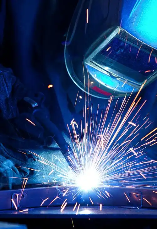
용접 강도가 실제로 의미하는 바
용접부는 얼마나 강한가? 간단히 말해, 특정 조건에서는 용접부가 모재(base metal)와 동등하거나 때로는 이를 초과할 수 있다. 그러나 실제 용접 강도는 용접 봉(weld bead) 자체 이상의 여러 요인에 따라 달라진다. 여기에는 모재, 이음부 설계(joint design), 용접 재료(필러 금속) 선택, 공정 제어, 청결도, 그리고 부품이 실제 사용 중 받는 하중 등이 포함된다.
용접부는 모재와 동등한 강도를 가질 수 있으나, 정확한 답변은 사용된 금속 종류, 이음부 형태, 용접 절차, 그리고 하중이 실제로 작용하는 위치에 따라 달라진다.
일상적인 언어로 설명한 용접 강도
용접부의 강도란 용접 부위 및 인근 금속이 지나치게 늘어나거나 균열이 발생하거나 파손되기 전까지 견딜 수 있는 힘의 크기를 의미한다. 즉, 단순히 반짝이는 한 줄의 용접선만 측정하는 것이 아니다. 일반적으로 세 개의 영역을 고려해야 한다.
- 용접 금속 용접부(용융 및 재응고된 재료): 이음부 내에서 용융되었다가 다시 응고된 재료로, 보통 모재와 필러 금속이 혼합된 형태이며, 'The Welder'에서 설명한 바에 따르면 이는 용접 작업자에 의해 형성된다.
- 열영향구역 열영향부(Heat-Affected Zone, HAZ): 용접부 바로 옆에 위치하며 용융되지는 않았으나 열에 의해 미세조직 및 기계적 성질이 변화된 금속 영역이다.
- 모재 용접부에서 원래의 금속을 분리시키는 부분으로, 기재 금속(base metal)이라고도 한다.
용접 강도가 기재 금속과 일치할 때
다음에서 제공하는 실용적인 지침: 팀 파이프라인(Team Pipeline) 핵심 포인트를 명확히 전달한다: 적절한 이음새 설계와 숙련된 용접 작업을 통해 용접 이음부는 접합되는 재료만큼 강할 수 있다. 이는 특히 충전재(fillers)가 호환되며, 융합(fusion)이 완전하고, 표면이 청결하며, 용접 절차가 해당 재료에 적합할 때 가장 가능성이 높다.
왜 용접부가 약점이 될 수도 있는가
열은 비드(bead)뿐만 아니라 더 많은 것을 변화시킨다. 열영향부(HAZ) 는 용융되지 않지만, 열 입력량과 냉각 조건이 부적절하게 제어될 경우 그 미세 구조 및 기계적 특성이 충분히 변화하여 인성 저하, 경도 증가 또는 균열 발생 위험 증가와 같은 문제가 발생할 수 있다. 따라서 겉보기에는 단단해 보이는 용접부라도 비드 근처에서 파손될 수 있으며, 혹은 이음새 배치 자체가 먼저 파손될 수도 있다. 이것이 바로 용접 강도(weld strength), 이음새 강도(joint strength), 그리고 전체 조립체 강도(whole-assembly strength)가 동일하지 않은 이유이다.
용접 강도는 이음새 강도와 동일하지 않다
비드는 이야기의 일부만을 전달할 뿐입니다. 조인팅 테크놀로지스(Jointing Technologies)는 용접 강도를 모호한 용어로 설명하는데, 이는 실제 결과가 기재 재료의 특성, 부품 구성 및 용접 파라미터에 따라 달라지기 때문입니다. 따라서 용접 금속에서는 우수한 강도가 나타나더라도 완성된 접합부에서는 여전히 부족할 수 있습니다. 강한 용접은 중요하지만, 이는 강한 접합부(joint)와 동일한 개념이 아니며, 어느 쪽도 자동으로 강한 조립체(assembly)를 보장하지 않습니다. 자동적으로 강한 조립체를 보장하지 않습니다 .
용접 금속 강도 대비 접합부 강도
사람들이 "실제로 용접은 어떤 기준으로 평가되는가?"라고 물을 때, 일반적으로 세 가지 서로 다른 수준이 혼합되어 논의됩니다. 이들을 구분하면 답변이 훨씬 명확해집니다.
| 용어 | 평가 대상 | 실패가 발생할 수 있는 위치 | 가장 중요한 설계 선택 사항 | 일반적인 예시 |
|---|---|---|---|---|
| 용접 금속 강도 | 적용된 용접 금속 자체 및 그 융착 및 충진 상태 | 비드 내부 또는 융착 불량, 기공, 균열과 같은 결함 부위 | 충전재 선택, 용접 조건, 침투 깊이, 열 관리 및 청결도 | 맞대기 용접은 두 개의 양호한 판재를 결합할 수 있으나, 융합이 불완전할 경우 비드 자체가 문제를 일으킬 수 있다 |
| 이음부 강도 | 용접 토우, 루트, 근처 가열 금속, 정렬 상태 및 이음새 형상 등 전체 용접 접합부 | 토우 부위, 루트 부위, 열영향부 또는 융합되지 않은 측면 벽을 따라 | 이음새 기하학적 형상, 맞물림 상태, 그루브 가공, 정렬 상태 및 매끄러운 용접 외형 | 코너 용접은 표면상으로는 적절해 보일 수 있으나, 언더컷 또는 충전 불량으로 인해 접합부 강도가 약화될 수 있다 |
| 조립체 강도 | 용접된 부품 또는 구조 전체와, 하중이 모든 연결 부재를 통해 전달되는 방식 | 용접부가 아닌, 부착된 판, 브래킷, 탭, 튜브 또는 인근 모재 내에서 발생함 | 부품 구성, 부착 배치, 구속 조건 및 조립체를 통한 하중 전달 경로 | 필렛 용접을 적용한 랩 조인트는 음향 비드가 양호할 수 있으나, 더 큰 연결부는 여전히 배치 방식에 의해 제한을 받는다 |
TWI는 이러한 구분을 더욱 실용적으로 만든다. TWI는 과잉 용접 금속(때때로 보강재라고도 함)이 자체적으로 강도를 향상시키는 경우는 드물다고 지적한다. 맞대기 이음에서는 선형 불정렬이 하중이 이음부를 통과하는 방식을 저해할 수 있으며, 융합 부족의 원인이 될 수도 있다. 필렛 이음 및 랩 형태의 연결부에서는 언더컷, 오버랩 또는 충전 불완전이 용접부의 국부적인 형상을 변화시키며, 이러한 형상 변화는 응력 집중 위치에 영향을 줄 수 있다.
조립 강도가 어떻게 정답을 변화시키는가
조립 강도는 용접선을 넘어서 더 큰 질문을 던집니다: 용접된 부품 전체가 실제 사용 중에 하중을 어떻게 전달하는가? 용접봉(비드)만큼 주변 부품도 중요합니다. 하중 경로가 힘을 한정된 작은 영역으로 집중시킨다면, 용접 금속이 파손되기 이전에 인근 부품이 먼저 파손될 수 있습니다. 이는 조인팅 테크놀로지스(Jointing Technologies)가 제시한 경고와 동일한 맥락입니다. 즉, 부품의 구성 방식이 용접부가 성공 지점이 될지 실패 지점이 될지를 결정합니다.
용접 접합부에서 가장 약한 부분이 위치할 수 있는 곳
가장 약한 영역은 용접 금속 내부, 토우(toe), 루트(root), 열영향부(HAZ), 또는 용접부 옆의 모재(parent material)에 있을 수 있습니다. 때로는 접합부 전체 외부, 즉 연결된 조립체 내부에 위치하기도 합니다. 이러한 약점 수준을 먼저 명확히 파악하는 것이 이후 모든 비교를 보다 정직하게 만드는 첫걸음입니다. 왜냐하면 인장, 전단, 충격, 반복 하중 등 다양한 하중 조건이 고려되면 ‘강도’라는 용어 역시 여러 가지 다른 의미를 가질 수 있기 때문입니다.
용접부의 인장 강도 및 기타 측정 지표
엔지니어에게 용접부의 강도가 얼마나 되는지 물어보면, 일반적으로 하나의 마법 같은 숫자가 아니라 여러 가지 측정값으로 나누어 대답합니다. 용접 접합부는 단순한 인장 시험에서는 우수한 성능을 보일 수 있으나 충격 하중, 저온 환경, 또는 수년간의 진동 조건에서는 어려움을 겪을 수 있습니다. 따라서 용접부의 강도란 사실상 다양한 종류의 하중 및 파손 형태를 각각 설명하는 일련의 기계적 특성으로 이해해야 합니다.
인장 전단 강도 및 충격 강도 설명
용접에서 사용되는 기본 기계적 특성 지침은 간단한 원칙에서 시작합니다: 용접부는 접합되는 기재 금속과 동등하거나 그 이상의 특성을 제공해야 합니다. 문제는 이러한 특성들이 모두 동일한 개념이 아니라는 데 있습니다.
- 인장 강도 : 재료가 파단되기 전까지 인장 하중에 견딜 수 있는 최대 하중입니다. 사람들이 용접부의 인장 강도 라고 말할 때, 일반적으로 용접부가 인장력에 의해 분리되는 것에 대한 저항력을 의미합니다.
- 전단 강도 : 한 부품이 다른 부품 위를 미끄러지려는 힘에 대한 저항력입니다. 이는 많은 필렛 용접 및 랩 조인트에서 중요합니다.
- 충격 인성 충격 하중 시 에너지를 흡수하는 능력. 용접부는 정적 하중에서는 양호해 보일 수 있으나, 충격 하중에는 파손될 수 있다.
- 연성 균열 없이 영구적으로 신장되거나 변형될 수 있는 능력. 낮은 연성은 용접 부위가 더 취성적으로 거동함을 의미한다.
- 피로 저항 반복 하중을 수차례 견디며 균열 없이 생존할 수 있는 능력. 이 특성은 실제 사용 환경에서 종종 진정한 한계 요소가 된다.
표시된 용접금속 강도는 기준치일 뿐, 실사용 환경에서 장기적인 내구성을 보장하지는 않는다.
실제 구조물에서 피로 저항성이 중요한 이유
피로는 많은 '강한 용접'이라는 가정이 무너지는 지점이다. A 금속학 용접된 연강 접합부에 대한 연구 결과, 피로 강도는 용접 토우(toe) 및 루트(root)의 형상, 잔류 응력, 미세조직, 경도, 기공과 같은 내부 결함에 의해 크게 영향을 받는다. 양호한 시공 품질의 용접 부위에서는 균열이 일반적으로 완전한 용접 금속을 통한 것이 아니라 필렛 용접의 용접 토우에서 시작되는 경우가 많다. 동일한 논문은 알루미늄 용접 사례를 인용하여, 최대 기공 지름을 0.06 mm에서 0.72 mm로 증가시켰을 때 1,000만 사이클에서의 피로 강도가 약 30퍼센트 감소했다고 언급한다.
이는 정적 인장 시험에서는 우수한 성능을 보였으나 진동, 반복 하중 또는 저온 사용 조건에서는 오히려 성능이 떨어질 수 있는 이유를 설명해 준다. 또한 고강도 재료의 용접이 단순히 더 강한 필러(filler)를 선택하는 문제만이 아님을 보여준다. 고강도 강재에서는 언더컷(undercut)과 같은 균열 유사 결함이 피로 저항성을 급격히 저하시킬 수 있다.
용접 등급 및 필러 분류가 기대 성능을 어떻게 안내하는가
용접 등급 및 필러 분류는 용착된 용접 금속에 대한 기대 성능을 설정하는 데 도움을 준다. 이는 AWS 분류 체계 aWS 분류 체계에서 접두사 'E'는 아크 용접 전극을 나타내며, 4자리 코드의 앞 두 자리 또는 5자리 코드의 앞 세 자리는 최소 인장 강도를 나타낸다. 예를 들어, E6010은 60,000 psi의 인장 강도를, E10018은 100,000 psi의 인장 강도를 의미한다. 나머지 숫자들은 용접 위치, 피복재 유형 및 전류 특성을 설명한다.
이러한 라벨은 특히 고강도 용접 응용 분야에서 유용하지만, 토우 형상(toe shape), 루트 품질(root quality), 잔류 응력(residual stress), 기공(porosity), 융합 부족(lack of fusion) 등은 반영하지 못한다. IIW 피로 가이드라인은 동일한 이유로 이러한 문제들을 심각하게 다룬다. 전극 상자에 표기된 숫자는 해당 충전재(fillers)가 제공하도록 설계된 성능을 알려준다. 절차 관리(procedure control)는 완성된 용접부가 실제로 그러한 성능을 달성했는지를 결정한다.
그리고 바로 여기서, 겉보기에는 양호해 보이는 용접부와, 실제 준비 상태, 침투 깊이, 열 입력량, 보호 조건, 결함 등을 고려할 때도 강도를 유지하는 용접부 사이의 본격적인 차이가 시작된다.
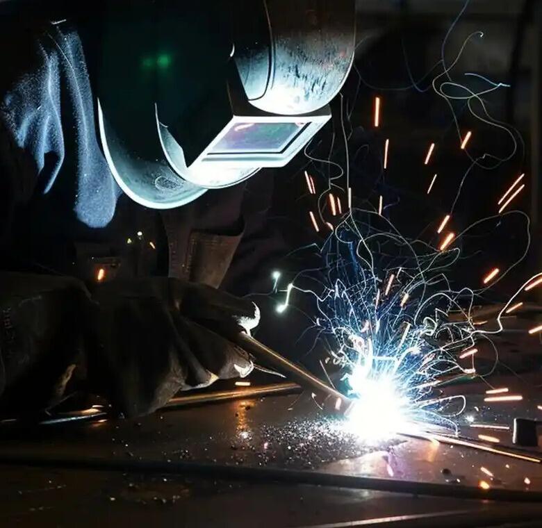
용접부의 강도를 결정하는 요소
두 개의 용접부는 표면상으로는 거의 동일해 보일 수 있지만, 하중을 받을 때는 매우 다른 거동을 보일 수 있습니다. 따라서 강한 용접은 아크가 시작되기 이전 단계에서부터 시작되며, 비드의 외관보다 훨씬 더 많은 요소에 의존합니다. 이음부 준비, 맞물림 정밀도, 용접재 호환성, 차폐 가스, 열 입력량, 이동 속도, 결함 제어 등이 모두 최종 결과를 형성합니다. 실무 작업장에서의 실제 작업 시 제작자 적절한 준비가 불순물 혼입, 슬래그 갇힘, 수소 균열, 융합 부족, 침투 부족 등을 방지하는 데 도움이 된다고 지적합니다. 따라서 ‘무엇이 용접부를 강하게 만드는가?’라는 질문에 답하려면, 이를 하나의 사슬로 생각해 보십시오. 이 사슬의 어느 위치라도 약한 연결 고리가 존재하면 완성된 이음부의 강도가 전반적으로 저하될 수 있습니다.
깨끗하고 매끄러운 비드는 설득력 있어 보일 수 있지만, 외관만으로는 용접부의 강도를 입증할 수 없습니다.
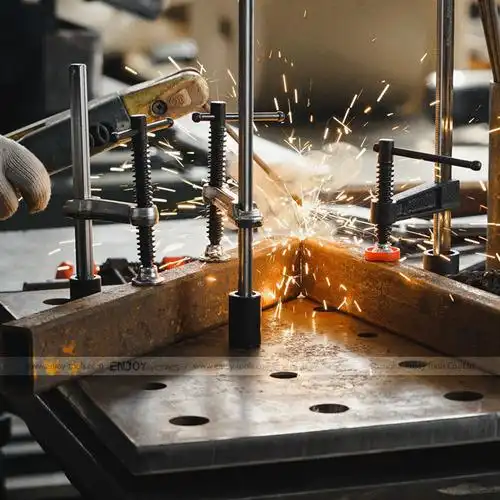
용접 강도를 높이거나 낮추는 공정 변수
공정 제어는 강도 향상 또는 저하가 많이 발생하는 지점이다. 적절한 표면 준비는 아크가 용접부의 루트 및 측벽에 접근할 수 있도록 해준다. 부적절한 표면 준비는 용접 시작 전에 이미 침투를 차단할 수 있다. 조립 정밀도 역시 동일하게 중요하다. 불량한 간격 또는 위치 오차 위에 형성된 양호한 비드라도, 근본적으로 약한 조립 상태에 놓이게 된다.
- 용접부 준비 : 비벨, 그루브 또는 엣지 형상은 인증된 공정과 일치해야 하며, 아크가 용접부에 적절히 도달할 수 있도록 해야 한다.
- 청결성 : 기름, 페인트, 먼지, 산화피막, 슬래그 또는 절단 잔여물 등은 용접부를 오염시켜 기공률 증가 또는 균열 발생 위험을 높일 수 있다.
- 피팅업 : 불균일한 간격, 부정확한 정렬 또는 불일치한 탭 용접은 침투 깊이와 일관성을 저하시킬 수 있다.
- 침투 및 융합 : 용접부는 설계에서 요구하는 바에 따라 루트 및 측벽에 결합되어야 하며, 단순히 상부에 금속을 쌓는 것만으로는 안 된다.
- 재료 및 보호 가스 호환성 : 용접재와 보호 가스는 기재 금속의 종류, 두께 및 용접 공정에 적합해야 한다.
- 입열량 및 이동 속도 열량이 너무 적으면 냉각 랩(cold lap) 또는 불완전 용접(fusion)이 발생할 수 있으며, 반대로 열량이 과도하면 언더컷(undercut), 변형(distortion), 또는 과도하게 확대된 열영향부(HAZ)가 유발될 수 있습니다.
- 위치 및 접근성 천장 방향(overhead), 수직(vertical), 또는 제한된 접근성(restricted access) 작업은 일관된 품질 유지가 더욱 어려워집니다.
- 잔류 응력 및 구속력 고정장치(fixturing), 용접 순서(sequence), 냉각 조건(cooling conditions)은 변형 및 균열 위험에 영향을 미칩니다.
용접 조건의 균형이 특히 중요합니다. 용접 기사는 전류(amperage)가 용입 깊이(penetration)에 영향을 주고, 전압(voltage)이 아크 길이(arc length) 및 비드 형상(bead profile)을 조절하며, 이동 속도(travel speed)가 열 입력량(heat input) 및 토우(tie-in) 접합 품질에 영향을 준다고 설명합니다. 전압이 지나치게 높으면 언더컷이 발생할 수 있고, 너무 낮으면 냉각 랩이 유발될 수 있습니다. 이동 속도가 너무 빠르면 용접부의 토우 부분에서 충분한 접합이 이루어지지 않을 수 있으며, 반대로 너무 느리면 과도한 열로 인해 비드 폭이 넓어지고 부재가 왜곡되거나 용입 품질이 저하될 수 있습니다.
열영향부(HAZ)의 변화가 부재 성능에 미치는 영향
용접부는 비드만으로 평가되지 않으며, 주변 금속도 변화하기 때문에 그렇습니다. 열영향부(HAZ)는 용융되지 않았지만 여전히 열 순환을 겪게 됩니다. 이 열 순환은 경도, 인성, 연성 및 균열 저항성을 변화시킬 수 있습니다. 높은 구속력, 급속 냉각 및 수소 흡수는 특히 용접금속 또는 HAZ 내 균열 발생을 촉진할 수 있으므로 매우 중요합니다. ESAB 결함 가이드에서는 또한 불균일한 가열 및 냉각이 용접 구조물을 왜곡시켜, 비드 상태가 양호하더라도 맞물림 정확도와 하중 전달 경로를 변화시킬 수 있음을 보여줍니다.
이 지점에서 흔히 믿어지는 오해 하나가 무너집니다. 더 많은 열이 자동으로 더 큰 강도를 의미하지는 않습니다. 때로는 고온·광폭 패스가 융합 달성에 도움이 되기도 하지만, 다른 경우에는 오히려 약화된 영역을 확대하거나 왜곡 및 잔류 응력을 증가시킬 수도 있습니다. 진정한 강도는 충분한 열을 사용하되, 부주의한 열을 사용하지 않는 데서 비롯됩니다.
왜 숙련도, 세팅 및 일관성이 중요한가
재현성은 용접 품질의 핵심 요소이다. 토치 각도, 스틱아웃(stick-out), 측벽에서의 정지 시간, 아크 길이, 그리고 안정적인 이동 속도 등은 용접부가 실제로 융합되었는지 아니면 겉보기만 융합된 것처럼 보이는지를 결정한다. 일부 가장 심각한 결함들은 외부에서 쉽게 식별하기 어렵다.
- 언더컷 용접 토우(toe) 부위에 형성된 홈으로, 단면적을 감소시키고 응력 집중을 증가시킨다.
- 성 오염, 수분 또는 불안정한 쉴딩(shielding)으로 인해 갇힌 가스.
- 용입 불량 용접 금속과 기재 금속 사이 또는 용접 패스 간에 완전히 접합되지 않은 상태.
- 관통 부족 완전 관통이 요구되는 경우, 이음새 전체 두께를 통한 뿌리 융합이 불완전한 상태.
- 균열 가장 심각한 결함 중 하나로, 일반적으로 구속 조건, 수소 또는 냉각 조건과 관련이 있다.
ESAB는 융합 불량(fusion)이 표면 아래에서 발생할 수 있어 단순한 육안 검사로는 간과되기 쉽다는 점을 지적합니다. 이는 사람들이 '용접부의 강도가 얼마나 높은가?'라고 물을 때 유용한 상기 시점입니다. 용접부는 매우 강할 수 있지만, 그 전제 조건은 재료 준비, 장비 설정, 그리고 기술이 부품 간 일관되게 조화를 이뤄야 한다는 것입니다. 바로 이러한 변수들이 여러 용접 공정이 모두 우수한 결과를 낼 수 있음에도 불구하고, 어떤 하나의 공정이 모든 경우에 항상 최선이 되지 못하는 이유이기도 합니다.
가장 강한 용접 공정은 무엇인가?
10명의 용접 기술자에게 가장 강한 용접 방식이 무엇인지 물어보면, 10가지 서로 다른 답변을 들을 수도 있습니다. 이는 질문 자체가 잘못되었기 때문이 아닙니다. 오히려 보편적으로 적용 가능한 ‘최고의’ 용접 공정이 존재하지 않기 때문입니다. MIG, TIG, 스틱(아크), 플럭스 코어드 용접 등 모두 강한 용접부를 생성할 수 있습니다. 진정한 차이는 각 공정이 특정 작업에 대해 열 관리, 보호 가스(실딩), 침투 깊이, 작업 속도, 그리고 작업자 제어 능력을 어떻게 다루는가에 있습니다.
RS, Weldguru 및 본 용접 공정 가이드에서 제공하는 종합적인 안내 동일한 결론을 지지한다: 사람들이 가장 강력한 용접 방식이 무엇인지 묻는다면, 정직한 대답은 재료, 두께, 이음부 접근성, 그리고 사용 조건에 따라 달라진다.
| 공정 | 주요 특징 | 강도 관련 장점 | 일반적인 제약 사항 | 작업자 의존성 | 청소 요구 사항 | 실용적인 사용 사례 |
|---|---|---|---|---|---|---|
| MIG 또는 GMAW | 보호 가스와 함께 사용하는 연속 와이어 전극 | 강철, 알루미늄, 스테인리스강에서 빠르고 효율적이며 다용도이며, 우수한 파라미터 제어를 통해 견고한 용접부를 생성할 수 있다. | TIG 용접보다 열영향부가 더 크고 튀는 스패터 발생 가능성이 높으며, 안정적인 보호 가스 및 설정에 의존한다. | 중간 | 중간 | 자동차 산업, 제조업, 일반적인 가공 작업 |
| TIG 또는 GTAW | 불활성 가스 보호를 받는 비소모성 텅스텐 전극 | 정밀한 열 제어, 작은 열 영향 구역, 깨끗한 용접, 낮은 스패터 발생량, 그리고 엄격한 작업 조건에서 뛰어난 피로 강도 | 공정 속도가 느리고 생산성이 낮음 | 높은 | 낮아 | 박판 재료, 고응력 부품, 외관 품질이 중요한 용접 |
| 스틱 용접(또는 SMAW) | 플럭스 코팅된 소모성 전극; 자체 차폐 방식 | 깊은 침투 깊이, 두꺼운 재료에 대한 강한 용접, 야외 작업 및 녹슬거나 더러운 표면에서도 유용함 | 이동 속도가 느리고, 전극 교체 빈도가 높으며, 스패터 발생량이 많고, 얇은 재료에서는 변형 위험이 큼 | 높은 | 높은 | 건설, 수리, 정비 및 원거리 현장 작업 |
| 플럭스 코어드 용접(또는 FCAW) | 플럭스를 충진한 관상 와이어; 자체 차폐 방식 또는 가스 차폐 방식 | 높은 용착률, 빠른 용접 속도, 우수한 생산성, 두꺼운 재료 및 구조용 강재에 대한 뛰어난 성능 | TIG 용접보다 용접 외관이 덜 세련됨, 슬래그 제거 작업이 여전히 필요하며, 일부 비철금속에는 적용 제한이 있음 | 중간 | 중간 ~ 높음 | 중형 제작, 조선업, 제조업 및 일부 자동차 정비 |
용접 강도 측면에서 MIG와 TIG 비교
MIG와 TIG의 비교 논쟁은 일반적으로 '가장 강한 용접 방식'을 찾는 검색어를 주로 유도합니다. RS 가이드에 따르면, 최대 강도와 피로 저항성이 요구되는 고응력 응용 분야에서는 일반적으로 TIG가 선호됩니다. 그 이유는 신비롭지 않습니다. TIG는 용접 작업자에게 더 정밀한 열 조절을 가능하게 하여 열영향부 영역 확장, 결정립 조대화 및 잔류 응력을 억제하는 데 도움을 줍니다. 또한, 정밀하게 조절된 필러 금속 추가와 불활성 가스 차폐는 기공 및 비금속 개재물 발생을 줄이는 데도 기여합니다.
그럼에도 불구하고 MIG는 여전히 존중받을 만합니다. 동일한 자료에 따르면, 공정 파라미터를 적절히 제어할 경우 MIG도 유사한 인장 강도를 달성할 수 있습니다. 또한 MIG는 훨씬 빠른 속도를 자랑하므로 대량 생산 환경에서는 특히 중요합니다. 따라서 가장 강한 용접 방식을 찾고 계신다면, 정밀도와 피로 민감 작업에서는 일반적으로 TIG가 우위를 점하지만, 속도, 반복성 및 재료 적용 범위가 더 중요한 경우에는 MIG도 탁월한 강도 성능을 제공할 수 있습니다.
강도가 중요한 작업에서 스틱 용접과 플럭스 코어 용접을 사용합니다
스틱 용접과 플럭스 코어 용접은 서로 다른 유형의 문제를 해결합니다. Weldguru는 스틱 용접을 강력하고 깊이 침투하는 방식으로, 특히 두꺼운 재료, 야외 환경, 그리고 완벽하지 않은 표면에 매우 유용하다고 설명합니다. 이는 실제 작업 조건이 열악하고 접근성이 제한된 상황에서 진지하게 고려해야 할 용접 방식입니다.
플럭스 코어 용접은 와이어가 연속적으로 공급되기 때문에 더 빠르고 생산성이 높습니다. 또한 스틱 용접보다 열 조절이 용이하며, 두꺼운 재료, 구조용 강재, 제조 작업 등에 널리 사용됩니다. 다만, 단점도 있습니다. Weldguru는 동일한 전류(암페어) 조건에서 스틱 용접이 플럭스 코어 용접보다 더 강하고 깊은 용접부를 형성할 수 있다고 지적합니다. 따라서 FCAW(플럭스 코어 아크 용접)가 자동으로 더 강한 선택지는 아닙니다. 보통은 더 빠른 선택지일 뿐입니다.
왜 가장 강한 용접 방식이 적용 분야에 따라 달라지는가
누군가 ‘가장 강한 용접 방식은 무엇인가?’라고 물을 때, 가장 유용한 답변은 다음과 같습니다:
- TIG 정밀도, 낮은 스패터 발생률, 피로 저항성이 핵심 요건일 때 종종 선호됩니다.
- MIG 일반적인 작업장 재료에 대해 강한 용접을 신속하게 수행해야 할 때 자주 선호된다.
- 스틱 두꺼운 판재, 야외 조건, 또는 불완전한 표면으로 인해 보다 깨끗한 공정이 실용적이지 않을 때 자주 선호된다.
- 플럭스 코어드(Flux-cored) 용착률과 중형 제작 생산성이 주요 우선 과제일 때 자주 선호된다.
따라서 가장 강한 유형의 용접은 특정 기계 이름과 연관되지 않는다. 이는 용접 대상 금속, 판 두께, 이음부 형상, 그리고 완성된 부품에 작용할 하중 조건에 가장 적합한 공정을 의미한다. 기초 재료를 변경하거나 단순 인장 하중을 굴곡, 전단, 진동 하중으로 바꾸기만 해도 최적의 답은 급격히 달라질 수 있다.
용접 이음부 설계, 재료 및 사용 하중
공정 선택은 중요하지만, 재료와 하중 경로가 용접 접합부가 안정적으로 유지될지, 아니면 약점이 될지를 종종 결정한다. 실제 제작 현장에서 일반 탄소강, 스테인리스강, 알루미늄, 고강도 합금 등은 열, 구속 조건, 또는 용가재 선택에 대해 동일한 방식으로 반응하지 않는다. 이것이 바로 우수한 용접 이음부 설계 종종 용접재 라벨에 표시된 높은 강도 수치보다 더 중요하다.
재료가 용접 강도에 미치는 영향
여기서 인용된 자료들은 스테인리스강만을 대상으로 하여 이를 명확히 보여준다. 호바트 브라더스(Hobart Brothers)는 스테인리스강이 부식 저항성과 극한 온도 환경에서의 사용을 위해 주로 선택되지만, 열 전도성이 낮아 낮은 열 입력이 매우 중요함을 지적한다. 동일 출처는 또한 스테인리스강 계열 간의 행동 차이를 보여준다. 페라이틱 스테인리스강은 일반적으로 오스테나이틱 및 마르텐사이트계 등급보다 강도가 낮다. 마르텐사이트 스테인리스강은 인장 강도가 높지만 연성은 낮고 수소균열 위험이 크다. 침석 경화형 스테인리스강은 열처리 후 200 ksi를 초과할 수 있다. 즉, 기재 금속(base metal)이 용접 설계의 규칙을 바꾼다. 탄소강, 스테인리스강, 알루미늄, 고강도 합금 등 일반적인 재료 간 전환 시에도 동일한 교훈이 적용된다: 용접은 단순히 용접 장비에 맞추는 것이 아니라, 재료 자체에 적합해야 한다.
모든 응용 분야에서 용접부가 볼트 연결보다 강한가?
모든 경우에 해당되는 것은 아닙니다. LNA의 지침에 따르면 용접 접합부는 인장, 압축 및 전단 하중을 견디기에 강하고 강성 있으며 효율적입니다. 동일한 비교에서는 볼트 접합부도 용접만큼 강할 수 있으며, 일부 배치에서는 오히려 더 강할 수 있다고 언급합니다. 또한 볼트 접합은 열 왜곡을 피하고 코팅을 보존하며 검사를 간소화하고 분해를 가능하게 합니다. 반면 용접은 영구적이며 소형이고 연속적인 접합이 요구될 때 여전히 명확한 이점을 가집니다. 따라서 질문하신다면, 용접부가 볼트보다 강한가요? 라는 질문에 대한 솔직한 답변은, 기하학적 구조, 접근성, 유지보수 요구사항, 그리고 하중이 전달되는 방식에 따라 각각이 상대적으로 우위를 점할 수 있다는 것입니다.
혹시 궁금하신가요 용접 접합부가 견뎌야 할 응력은 무엇인가요? 정답은 일반적으로 다음과 같습니다:
- 긴장 및 압축 직접 하중에 의한 응력.
- 전단 부재들이 서로 미끄러지려는 힘에 의한 응력.
- 굽는 힘의 작용 방향이 접합선에서 멀어지는 경우 발생하는 응력.
- 톱션 편심 하중, 열 팽창/수축 또는 불균일한 지지로 인해 발생하는 응력으로, SPS Ideal Solutions .
- 진동 및 영향 정적 강도가 양호해 보일지라도 피로 위험을 증가시킵니다.
접합부 설계 변경이 가장 약한 지점을 어떻게 바꾸는가
| 조인트 유형 | 쉬운 용어로 설명 | 효과적으로 작동하는 경우 | 흔히 발생하는 약점 연결 위험 |
|---|---|---|---|
| 엉덩이 관절 | 두 부품이 동일 평면에서 모서리 대 모서리로 만나는 방식 | 직접적인 하중 전달 경로와 깔끔한 힘 전달 | 정렬 불량 또는 완전한 침투 부족으로 인해 강도가 급격히 감소할 수 있음 |
| 필렛 이음매 | 삼각형 형태의 용접부가 각도를 이루는 표면들을 연결하며, 일반적으로 T자 이음부에 사용됨 | 많은 제작 작업에 공통적이고 실용적이며 효율적임 | 특히 피로 또는 비틀림 하에서 토우(toe) 및 루트(root) 부위의 응력 집중 |
| 관절 | 한 부품이 다른 부품 위에 겹쳐지는 방식 | 간단한 조립 및 얇은 부품에 유용함 | 편심 하중으로 인해 겹침 접합부에 박리, 굽힘 및 전단 응력이 추가될 수 있음 |
| 그루브 용접(groove weld) | 깊은 융착을 위해 준비된 그루브 내에 수행되는 용접 | 전면 용입(full penetration)이 필요한 경우 더 나은 하중 전달 성능 | 용접비드의 외관뿐 아니라, 그루브 가공 정밀도 및 융착 품질이 매우 중요해짐 |
SPS는 또한 접합부 기하학이 비틀림 성능에 중대한 영향을 미친다고 지적합니다. 단순한 필렛 용접(fillet weld)은 일부 하중 조건에서는 잘 대응할 수 있으나 비틀림 저항력은 제한적일 수 있습니다. 반면, 보다 완전한 용입과 개선된 접합부 상세 설계는 강성을 향상시킬 수 있습니다. 따라서 서류상의 등급 용접 강도는 단지 출발점일 뿐입니다. 진정한 검증은 실제 사용 환경에서, 조립 정밀도, 변형, 접근성 제약, 그리고 검사 현실 속에서 완성된 접합부가 어떻게 작동하는지를 통해 이루어집니다.
표시된 용접 강도 대 실제 성능
접합부는 서면상으로는 강해 보일 수 있으나, 현장에서는 실망스러운 결과를 초래할 수도 있습니다. 공식적으로 발표된 필러 금속 분류, 시편 시험, 및 규격 인증은 기준선을 설정하지만, 이는 모든 양산 용접이 실제 사용 조건에서 동일한 방식으로 작동함을 보장하지는 않습니다. 실제 성능은 부품의 맞물림 정밀도, 접근성, 고정장치, 열 관리, 왜곡 제어, 그리고 부품 간 일관된 고품질 용접 결과 재현 가능성에 따라 달라집니다.
표시된 용접 강도 대 서비스 성능
여기서 많은 사람들이 오해합니다 가장 강한 용접이란 무엇인가 . 표시된 전극 또는 인증된 시험 시편은 제어된 조건 하에서 해당 공정이 달성할 수 있는 성능을 알려줍니다. WPS, PQR 및 WPQR 에 대한 안내 자료는 논리를 명확히 보여줍니다: 먼저 용접 절차서(WPS)를 작성하고, 그 절차에 따라 시험편을 용접한 후, 적용 가능한 규격에서 요구하는 바에 따라 시각 검사, 파괴 검사 및 비파괴 검사를 통해 결과를 검증합니다. 이는 공정 능력을 입증하는 것이지, 양산 과정에서 발생할 수 있는 변수들을 무효화하지는 않습니다.
실제 제조 과정에서는 단일 통과 시편(쿠폰)만큼 반복성(repeatability)도 중요합니다. 올 메탈스 파브리케이션(All Metals Fabrication)의 공정 관리 지침은 고정장치(fixturing), 기준면(datum) 제어, 용접 순서(weld sequence), 그리고 공정 중 검증(in-process verification)을 강조하는데, 이 영역에서의 편차(drift)는 명목상의 설정 값이 동일하게 유지되더라도 비드 형상(bead shape), 침투 깊이(penetration), 왜곡(distortion)을 변화시킬 수 있기 때문입니다.
용접부가 충분히 강한지 여부를 판단하는 방법
혹시 궁금하신가요 용접 강도를 시험하는 방법 실용적인 방식으로 계층적 접근법(layered approach)을 사용합니다:
- 절차 확인 : 용접이 적격화된 용접 절차서(WPS), 사전적격화 절차(prequalified procedure) 또는 기타 승인된 표준에 따라 수행되었는지, 필요 시 지지 자료로서 절차적격시험보고서(PQR) 또는 이와 동등한 문서가 있는지를 확인합니다.
- 시각 검사를 우선 실시 : 골든 인스펙션(Golden Inspection)은 허용 가능한 용접부는 깔끔하게 보여야 하며, 필요한 경우 완전한 루트 융합(root fusion)이 나타나고, 모재(parent material)에 부드럽게 융합되어야 하며, 결함 없이 상당히 깨끗해야 한다고 지적합니다.
- 적격화가 필요할 때 파괴 시험을 실시 참고문헌에 나열된 일반적인 예시로는 굽힘 시험, 횡방향 인장 시험, 경도 시험, 닉 브레이크 시험, 매크로 에칭 시험, 샤피 충격 시험 등이 있다.
- 생산 부품을 보존해야 할 경우 비파괴 검사를 추가한다 용접 검사 방법으로는 방사선 검사, 초음파 검사, 자분 검사, 침투 검사 등이 일반적으로 사용되며, 각각 결함 유형 및 재료에 따라 적합하게 적용된다.
검사 및 반복성의 중요성
강도를 위한 용접 검사 이는 단순히 후행적으로 불량 용접봉을 찾아내는 것을 넘어서, 공정의 안정성을 입증하는 것이다. 하나의 시험용 시편에서 용접이 합격 판정을 받았다고 해서 실제 생산 시에도 변동성이 없는 것은 아니다. 예를 들어, 조립 고정장치 내 부품의 장착 방식이 달라지거나, 접근 조건의 변화로 인해 토치 각도가 달라지거나, 후속 용접 전에 변형으로 인해 이음부 위치가 이동하는 경우, 생산 중 용접 품질이 달라질 수 있다. 따라서 체계적인 작업 지침서, 일관된 고정장치 사용, 정기적인 검사 점검이 강도 관리의 일부이며, 단순한 서류 작업이 아니다.
강도를 단일 시험 결과가 아니라 반복 가능한 시스템으로 간주할 경우, 구매 관련 질문 역시 달라진다. 진정한 핵심은 용접 파트너가 양산 압력 하에서도 이 시스템을 안정적으로 유지할 수 있는지 여부이다.
강도가 중요한 부품을 위한 섀시 용접 파트너 선정
자동차 조달 분야에서는 강도 관련 질문이 매우 실용적인 수준으로 빠르게 전환된다. 섀시 브래킷, 크로스멤버 부품 또는 서스펜션 관련 용접 조립체는 견적 검토 단계에서는 외관상 문제가 없어 보일 수 있으나, 공급업체가 양산 과정에서 맞물림 정확도, 용입 깊이 및 추적 가능성을 확보하지 못할 경우 현장에서 위험을 초래할 수 있다. 따라서 자동차 용접 공급업체 선정은 영업 주장보다는 공정 검증에 더 중점을 두어야 한다.
자동차 구매 담당자가 용접 강도와 관련해 확인해야 할 사항
- 재료 및 공정 능력 공급업체가 귀사의 프로그램에 따라 강철 및 알루미늄 등 금속을 적절한 두께, 접근성, 내구성을 고려한 공정으로 용접할 수 있는지 확인하세요. JR 오토메이션은 자동차 부품 조립 방식 선택 시 재료 종류, 두께, 형상, 정비 용이성, 성능 요구사항을 모두 충족해야 한다고 지적합니다.
- 지그 및 기준점 제어 부품이 어떻게 위치 지정되고, 클램프로 고정되며, 검사되는지 문의하세요. 이동식 지그에서 양호한 용접 비드가 형성되었다 하더라도 조립체 전반의 강도는 약해질 수 있습니다.
- 문서화된 품질 시스템 iATF 16949 인증서를 포함하여 APQP, PPAP, PFMEA, 관리 계획, MSA, SPC 및 주요 특성에 대한 변경 관리 체계를 증명할 수 있는 자료를 요청하세요.
- 검사 추적성 용접 기록이 로트 ID, 재료 인증서, 검사 결과와 연계되어 있는지 확인하세요. JR은 파라미터 기록 및 추적성이 자동차 산업의 핵심 기대 사항임을 강조합니다.
- 납기 준수 체계 샘플 제출 일정, 양산 속도(production rate) 대비 준비 상태, 그리고 설비 또는 공구 문제 발생 시 대응 계획을 점검하세요.
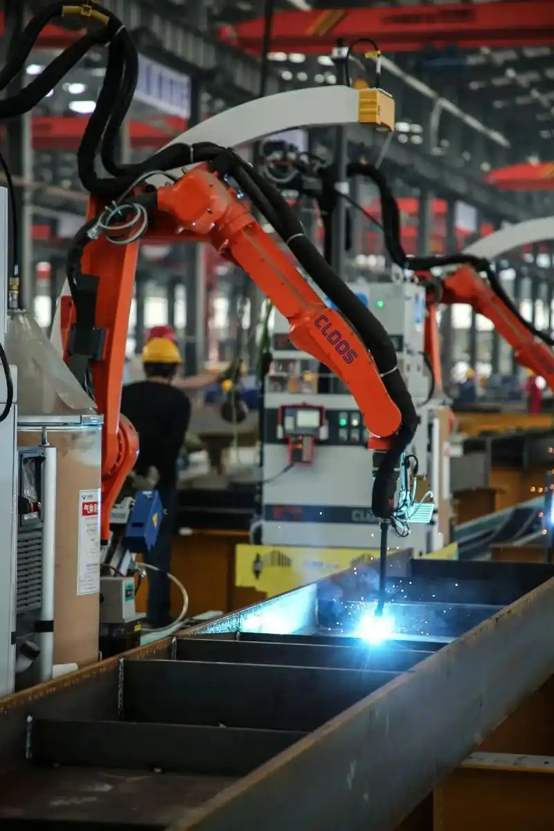
로봇 용접 및 품질 시스템이 일관성을 지원하는 이유
로봇은 자동으로 품질을 보장하지 않습니다. 가장 강력한 용접 방식 이러한 시스템은 일관성 관리를 보다 쉽게 만들어 줍니다. JR은 전류, 가압력, 토치 이동 경로 및 비드 형상의 변동을 최소화하는 자동화된 점용접 및 아크 용접 시스템을 설명합니다. 강도가 중요한 섀시 작업에서는 반복 가능한 지그 설계와 파라미터 기록이 재작업을 줄이고, 품질 편차 발생 시 근본 원인 분석을 신속하게 수행할 수 있도록 해 주기 때문에 이 점이 매우 중요합니다.
샤오이 메탈 테크놀로지(Shaoyi Metal Technology)가 특화된 섀시 작업에 부합하는 이유
- 소이 메탈 테크놀로지 : 관련성 있는 하나의 섀시 용접 협력사 로서, 특화된 자동차 용접 부품을 검토할 때 고려해 볼 수 있습니다. 샤오이는 첨단 로봇 용접 라인과 강철, 알루미늄 및 기타 금속에 대한 맞춤형 용접 서비스를 제공하며, IATF 16949 품질 관리 시스템을 갖추고 있습니다. IATF 16949 품질 시스템 또한 서비스 정보에는 가스 차폐 아크 용접, 일반 아크 용접, 레이저 용접뿐 아니라 용접 조립체에 대한 초음파 검사(UT), 방사선 검사(RT), 자석 입자 검사(MT), 침투 검사(PT), 와전류 검사(ET), 인발 시험(pull-off testing) 등이 명시되어 있습니다.
- 후보군에 선정된 공급업체의 경우 : 실제 평가 기준은 해당 팀이 귀사의 부품과 유사한 부품에 대해 안정적인 지그, 승인된 용접 절차, 추적 가능한 검사 기록 및 반복 가능한 생산 결과를 실제로 제시할 수 있는지 여부입니다.
최고의 파트너는 일반적으로 역량 브로슈어에서 잘 설명하는 것뿐 아니라, 실제 양산 압박 상황 속에서 공동의 역량을 입증할 수 있는 파트너이다.
자주 묻는 질문
1. 용접부가 기재 금속보다 강할 수 있습니까?
예. 적절히 설계되고 정확하게 수행된 용접은 제어된 시험 조건 하에서 주변 기재 금속과 동등하거나, 경우에 따라 그 이상의 성능을 발휘할 수 있습니다. 그러나 이는 용접재가 기재 금속에 적합하고, 이음부가 올바르게 설계되었으며, 융합이 완전하고, 열영향부가 부적절한 공정 관리로 인해 약화되지 않을 때에만 가능합니다.
2. 용접 접합부 중 어느 부분이 일반적으로 가장 먼저 파손됩니까?
항상 용접 비드 자체가 먼저 파손되는 것은 아닙니다. 파손은 종종 용접 토우(toe), 루트(root), 열영향부(heat-affected zone), 또는 하중 경로, 맞물림(fit-up), 이음부 형상 등으로 인해 응력 집중이 발생하는 인근 모재(parent material)에서 시작됩니다. 따라서 엔지니어는 용접금속 강도, 이음부 강도, 조립체 강도를 구분하여 고려합니다.
3. 어떤 용접 공정이 가장 강한 용접부를 만들 수 있습니까?
모든 작업에 대해 단 하나의 가장 강력한 용접 공정은 존재하지 않습니다. TIG는 정밀하고 피로에 민감한 작업에 자주 선택되며, MIG는 반복적인 양산 용접에 적합한 강력한 옵션입니다. 또한 스틱 용접 또는 플럭스 코어드 용접은 두꺼운 재료나 까다로운 현장 조건에서 매우 우수한 성능을 발휘할 수 있습니다. 최상의 결과는 재료, 두께, 접근성 및 사용 하중에 따라 적절한 용접 공정을 선택하는 데서 비롯됩니다.
4. 용접부가 충분히 강한지 어떻게 알 수 있습니까?
우선, 용접이 승인된 절차 또는 인정된 표준에 따라 수행되었는지 확인하세요. 그 후, 외관 품질, 조립 정확도(피트업), 그리고 결함이 발생하기 쉬운 부위를 점검하고, 적용 분야에서 보다 확실한 검증이 요구될 경우 파괴 시험 또는 비파괴 시험을 실시합니다. 보기 좋게 정돈된 용접 라인이더라도 융착 불량, 기공 등 실제 사용 성능을 저하시키는 문제를 숨기고 있을 수 있습니다.
5. 자동차 제조사가 섀시 부품용 용접 업체를 선정하기 전에 점검해야 할 사항은 무엇입니까?
검증된 공정 능력, 안정적인 지그 및 피ク스처링, 반복 가능한 로봇 또는 수동 제어, 검사 추적성, 그리고 IATF 16949와 같은 문서화된 자동차 품질 관리 시스템을 확인하세요. 또한, 공급업체가 철강 및 알루미늄을 포함한 귀사 프로그램에서 사용되는 금속을 처리할 수 있는지, 동시에 납기 준수를 희생하지 않는지 여부도 확인하는 것이 유익합니다. 샤오이 메탈 테크놀로지(Shaoyi Metal Technology)는 로봇 용접 라인, 다양한 금속에 대한 맞춤형 용접, 자동차 중심의 품질 관리를 강조하는 관련 있는 평가 대상 업체 중 하나입니다. 그러나 최적의 공급업체는 귀사 부품과 유사한 부품에 대해 일관된 결과를 문서화할 수 있는 업체입니다.