 Small batches, high standards. Our rapid prototyping service makes validation faster and easier —

Key Factors for Press Compatibility in Die Design

TL;DR
Press compatibility in die design is the engineering process of ensuring a die's physical and operational specifications precisely match a press machine's capabilities. This alignment is critical for safe, efficient, and high-quality production in sheet metal stamping. Key parameters that must be perfectly synchronized include the die height versus the press's shut height, the required tonnage, and the die's footprint relative to the press bed size.
The Core Relationship: Why Press and Die Interaction Matters
In manufacturing, a press machine and a stamping die function as a single, integrated system. The performance of the press is directly influenced by the quality and design of the die. Achieving perfect compatibility between these two components is not merely a technical detail; it is fundamental to ensuring production quality, protecting expensive machinery, and maintaining a safe operating environment. A well-designed die ensures that metal is shaped accurately, leaving no room for error, while a poor design can lead to increased wear and tear on the machine, lower productivity, and higher operating costs.
A mismatch between the die and the press can introduce a host of problems. One of the most significant is the risk of an eccentric load, which occurs when the center of force applied by the die is not aligned with the center of the press slide. This misalignment can cause the slide to tilt, leading to uneven wear on the press, premature die failure, and inconsistent part quality. The consequences of such a mismatch range from minor defects in the final product to catastrophic damage to the press itself, resulting in costly downtime and repairs.
Therefore, die design is a strategic process that balances the requirements of the part with the capabilities of the press. Designers must consider whether to create a die for a specific press or a more universal design that can run in multiple machines. This decision impacts initial tooling costs, setup times, and production flexibility. Ultimately, a deep understanding of the interaction between the die and press is essential for creating a robust and profitable manufacturing system. For complex applications, such as those in the automotive sector, partnering with specialists is crucial. For instance, Shaoyi (Ningbo) Metal Technology Co., Ltd. excels in creating custom automotive stamping dies, ensuring that these critical design principles are expertly applied to meet the stringent demands of OEMs and Tier 1 suppliers.
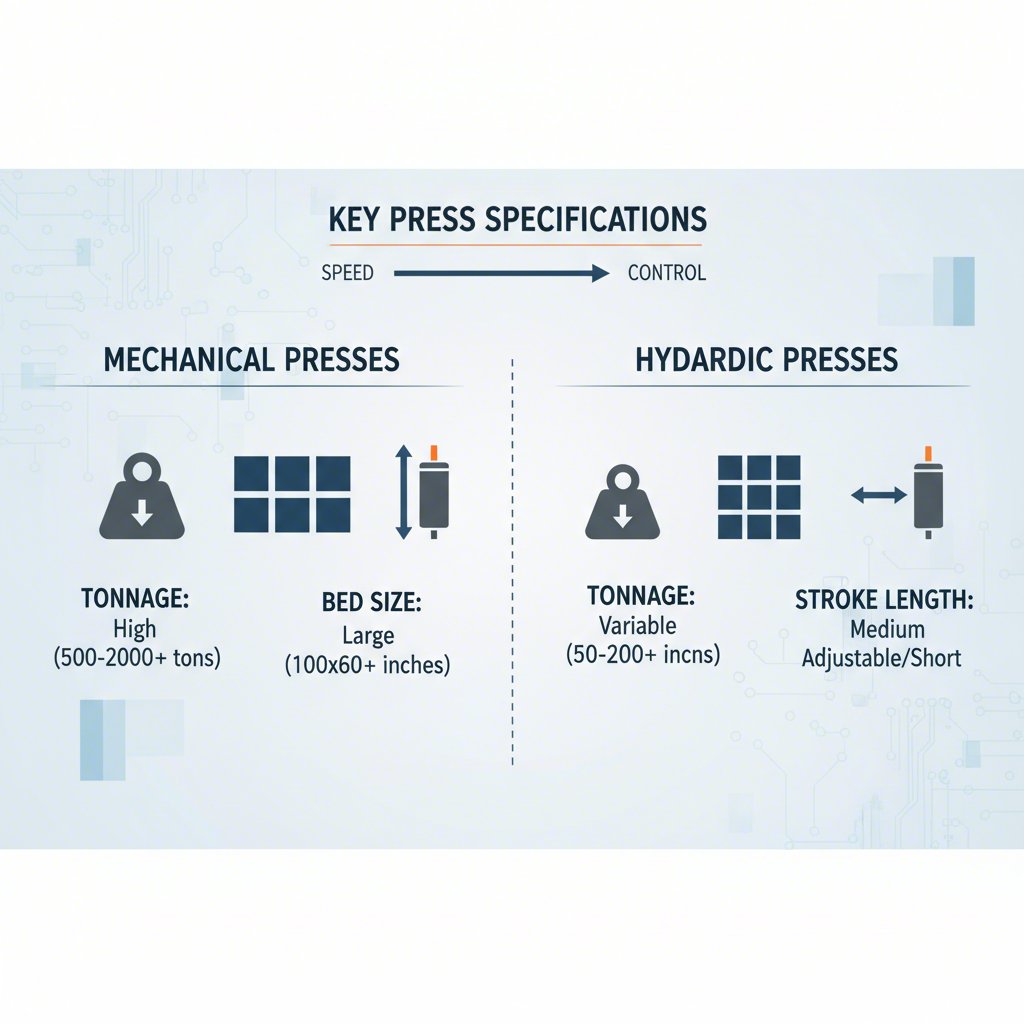
Critical Press Specifications: Matching Tonnage, Size, and Speed
A thorough evaluation of the press machine's technical specifications is a non-negotiable step in die design. Every press has a unique set of capabilities, and the die must be engineered to operate within these limits. According to an article from The Fabricator, key specifications include tonnage, bed size, strokes per minute, stroke length, and shut height. Overlooking any of these parameters can lead to production failures or equipment damage.
To ensure proper alignment, designers must verify several core parameters:
- Tonnage: This is the maximum force the press ram can exert. The die designer must calculate the total force required for all cutting and forming operations. The press's nominal tonnage must exceed this calculated force, typically with a safety margin of 20-30% to account for material variations and tool wear.
- Bed Area: The bed is the mounting surface for the lower portion of the die. The die's footprint must fit comfortably within the press bed's dimensions, leaving adequate space for clamping and without any interference.
- Stroke Length: This is the total vertical travel distance of the press slide. The stroke must be long enough to allow for material feeding, part formation, and safe ejection of the finished component.
- Strokes Per Minute (SPM): This defines the operational speed of the press. The die's design, including its feeding and ejection systems, must be capable of running reliably at the target speed without causing jams or part defects.
The following table summarizes these critical press specifications for quick reference:
| Specification | Definition | Die Design Consideration |
|---|---|---|
| Tonnage | The maximum force exerted by the press ram. | Calculated die force must be less than the press tonnage, including a safety margin. |
| Bed Area | The mounting surface size of the press bolster. | The die set's footprint must fit within the bed area with space for clamps. |
| Stroke Length | The vertical travel distance of the slide. | Must be sufficient for part formation, feeding, and ejection. |
| SPM (Strokes Per Minute) | The cycling speed of the press. | The die must be designed to run reliably at the required production speed. |
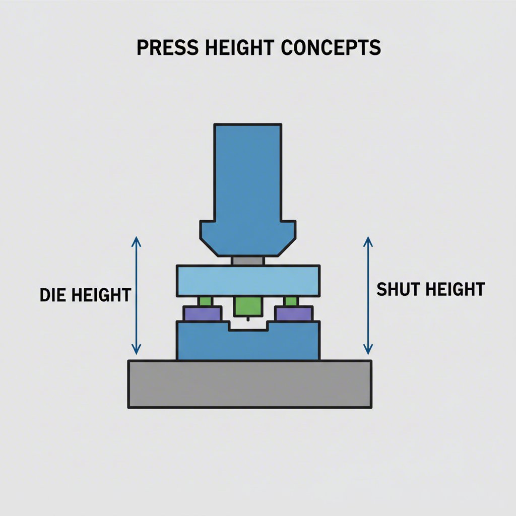
Understanding Die Height and Shut Height: The Critical Vertical Dimension
Among all compatibility factors, the relationship between the die height and the press's shut height is arguably the most critical. These terms define the vertical operating window of the press and die system. A misunderstanding of this relationship can make it physically impossible to install or run a die. As explained by MISUMI Tech Central, these two measurements are distinct but interconnected.
First, let's define the terms. The shut height of a press is the distance from the top surface of the bolster plate to the bottom surface of the slide when the slide is at the bottom of its stroke (bottom dead center) and the slide adjustment is at its maximum setting. This represents the maximum vertical space available for a die. The die height is the total height of the die set when it is fully closed, from the bottom of the lower die shoe to the top of the upper punch holder.
The fundamental rule is that the die height must be less than the press's maximum shut height. If a die is taller than the press's shut height, it simply will not fit. Conversely, if a die is significantly shorter, the press's slide adjustment mechanism is used to lower the slide and compensate for the difference. If the die is too short to be accommodated by the adjustment range, spacer plates known as parallel blocks or risers are used to make up the difference.
To ensure compatibility, a designer or technician should follow a clear verification process:
- Determine the Press Shut Height: Obtain the maximum and minimum shut height specifications from the press machine's manual.
- Establish the Die Height: The die design must specify a precise die height in its closed position. This is a critical dimension on the final assembly drawing.
- Verify the Fit: Confirm that the designed die height falls within the press's adjustable shut height range. For efficiency, it is a best practice to standardize die heights for all tools running in the same press to minimize adjustment time during changeovers.
- Account for Grinding: Consider that die components will be sharpened over time, which slightly reduces the overall die height. The press adjustment must be able to compensate for this change throughout the tool's life.
Die Construction and Mounting: Securing the System for Operation
Beyond dimensional compatibility, the physical construction of the die and its mounting method are essential for safe and stable operation. The die set—comprising the upper and lower die shoes—serves as the foundation for all tooling components. These plates must be rigid enough to withstand the immense forces of stamping without deflection, which could lead to misalignment and part defects.
Key components in die construction include:
- Die Sets and Shoes: These are the upper and lower plates that hold the punches, die buttons, and other tooling. Their material and thickness are critical for maintaining rigidity.
- Guide Pins and Bushings: These elements ensure precise alignment between the upper and lower halves of the die during operation. Proper lubrication and fit are necessary for smooth, wear-free movement.
- Stripper Plates: These plates hold the material flat during the operation and strip it off the punches as the press slide retracts.
- Fasteners: The method used to secure the die to the press is critical for safety. According to MetalForming Magazine, T-bolts and nuts are a preferred and widespread method for securely fastening dies to the press bed and slide.
Best practices for die construction and mounting are crucial for ensuring both part quality and operator safety. A well-designed die anticipates the entire manufacturing process, from setup to maintenance. This includes designing tooling and fixtures that can only be inserted in one direction to prevent errors, clearly noting lubrication requirements, and indicating maintenance intervals. According to a guide on die design best practices, understanding the part's design intent is vital to creating a tool that is not only accurate but also efficient and manufacturable.
Frequently Asked Questions About Press and Die Compatibility
-
1. What is the difference between die height and shut height?
Shut height is a specification of the press machine, representing the distance from the bed to the slide at the bottom of its stroke. Die height is a specification of the tool, representing its total height when fully closed. For compatibility, the die height must fit within the press's adjustable shut height range.
-
2. What happens if the press tonnage is too low for the die?
If the press tonnage is insufficient, it will be unable to provide the force needed to cut or form the material properly. This can result in incomplete forms, poor quality parts, and can even cause the press to stall or sustain damage from overloading.
-
3. Can a single die be used in different press machines?
Yes, but only if the press machines have compatible specifications. The die's height, footprint, and tonnage requirements must align with the capabilities of each press. Standardizing die heights and using common clamping methods can make it easier to move dies between similar machines.