 Small batches, high standards. Our rapid prototyping service makes validation faster and easier —

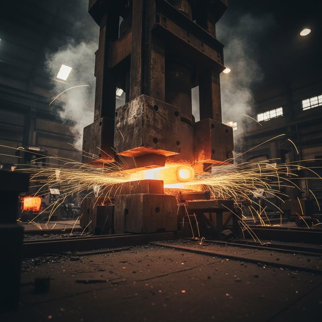
Impact Of Forging On Metal Fatigue: Why Grain Flow Changes Everything
Understanding Metal Fatigue and Why It Matters
Imagine a critical aircraft component that has passed every inspection, yet suddenly fails mid-flight. This nightmare scenario became reality during Southwest Airlines Flight 1380 in April 2018, when metal fatigue caused a fan blade failure with devastating consequences. The unsettling truth? Metal fatigue remains one of the most dangerous and misunderstood phenomena in engineering—and understanding it is essential before exploring how forging can dramatically improve component longevity.
So what exactly is metal fatigue? Think of it as the progressive structural damage that occurs when materials experience repeated stress cycles, even when those stresses fall well below their ultimate tensile strength. Unlike sudden overload failures that happen when you exceed a material's breaking point, fatigue develops silently over thousands or even millions of loading cycles. A component might handle each individual stress application without any apparent issue, yet microscopic damage accumulates until catastrophic failure occurs without warning.
Why Metal Components Fail Under Repeated Stress
Here's what makes fatigue particularly treacherous: it can occur at stress levels that seem perfectly safe according to standard engineering calculations. When you bend a paperclip back and forth until it breaks, you're witnessing fatigue in action. Each bend applies stress far below what would snap the wire in a single pull, yet the cumulative effect eventually causes failure.
Every manufactured component contains microscopic imperfections—tiny voids, inclusions, or surface scratches that are virtually undetectable during inspection. Under repeated loading, these minuscule defects become the starting points for cracks that grow incrementally with each stress cycle. The stress concentrated at a crack tip can cause localized yielding even when the overall calculated stress remains well below the yield strength.
This reality presents engineers with a fundamental challenge: how do you select manufacturing processes that minimize these internal defects and create structures resistant to crack formation and growth? This is precisely where understanding what are forgings and the advantages of forging becomes crucial for fatigue-critical applications.
The Three Stages of Fatigue-Induced Failure
Metal fatigue doesn't happen instantaneously. Instead, it progresses through three distinct stages that engineers must understand to design durable components:
- Stage 1: Crack Initiation — As a material undergoes repeated stress cycles, micro-cracks begin forming at points of high stress concentration. These cracks are often microscopic and invisible to the naked eye. The stress required to initiate these micro-cracks can be significantly less than the material's ultimate tensile strength, making early detection extremely difficult.
- Stage 2: Crack Propagation — With continued cyclic loading, initial cracks begin expanding and propagating through the material's weakest paths. Each stress cycle causes the crack to grow slightly larger, concentrating even more stress at the crack tip. This stage can consume most of the component's fatigue life, with cracks branching out and following paths of least resistance through the material's structure.
- Stage 3: Sudden Fracture — The final stage occurs when the remaining cross-section can no longer withstand the applied load. Failure happens suddenly and acutely, often without warning—especially if the initiation and propagation stages went undetected. By this point, intervention is impossible.
Understanding these stages reveals why material integrity matters so much. Components forged in metal typically exhibit superior resistance to crack initiation because the forging process eliminates many of the internal defects where cracks would otherwise begin. This foundational knowledge sets the stage for understanding why manufacturing method selection—particularly the choice to forge rather than cast or machine from solid stock—can determine whether a component survives millions of stress cycles or fails unexpectedly in service.
The Forging Process Explained
Now that you understand how metal fatigue develops and why internal defects trigger catastrophic failures, a natural question emerges: what manufacturing process best eliminates those defects while creating structures inherently resistant to crack propagation? The answer lies in forging—a process that fundamentally restructures metal at the molecular level to deliver superior fatigue performance.
Forging is defined as the plastic deformation of metals at elevated temperatures into predetermined shapes using compressive forces exerted through dies. Unlike casting, which pours molten metal into molds, or machining, which removes material from solid stock, forging reshapes metal while it remains in a solid state. This distinction matters enormously for fatigue resistance because the compressive forces applied during forging refine the microstructure, eliminate hidden defects like hair cracks and voids, and rearrange the fibrous macrostructure to conform with metal flow.
How Forging Reshapes Metal at the Molecular Level
When you heat metal to its forging temperature, something remarkable happens at the atomic level. The thermal energy increases atom mobility, allowing the crystalline grain structure to reorganize under applied pressure. This process—called plastic deformation—permanently changes the material's internal architecture without breaking it apart.
Consider the upset forging definition: a process where compressive forces increase cross-sectional area while decreasing length. During upsetting in forging, the metal's grain boundaries realign perpendicular to the applied force, creating a denser, more uniform structure. This grain refinement directly translates to improved fatigue properties because smaller, more uniform grains provide greater resistance to crack initiation and propagation.
The upset forging process typically involves securing a round bar with gripping dies while another die advances toward the exposed end, compressing and reshaping it. This technique is commonly used to form fastener heads, valve ends, and other components requiring localized material buildup at stress concentration points.
Temperature control proves critical during this transformation. Hot forging occurs above the metal's recrystallization temperature—typically between 850 and 1150 degrees Celsius for steel, and up to 500 degrees Celsius for aluminum. At these temperatures, internal stresses are relieved as new grains form, enhancing mechanical properties including strength and ductility while maintaining material integrity.
From Raw Billet to Refined Component
The journey from raw metal stock to a fatigue-resistant forged component follows a carefully controlled sequence. Each step influences the final metallurgical properties that determine how the part will perform under cyclic loading:
- Die Design and Manufacturing — Before any metal is heated, engineers design dies that will control grain flow, ensure proper material distribution, and minimize waste. A well-designed die promotes directional strength aligned with anticipated stress patterns in the finished component.
- Billet Preparation — Raw billets or ingots with appropriate cross-sections are cut to specified lengths. The starting material's quality directly impacts the final product, making proper stock selection essential for fatigue-critical applications.
- Heating to Forging Temperature — The metal is heated in a furnace until it reaches optimal plasticity. This temperature varies by material—steel requires 850-1150°C while aluminum needs only around 500°C. Proper heating ensures the metal will flow uniformly without cracking during deformation.
- Plastic Deformation — The heated metal moves to the die where compressive forces reshape it. Multiple passes through various dies may be necessary, with reheating between stages if required. During this step, internal voids collapse, porosity eliminates, and grain structure refines—all factors that directly improve fatigue resistance.
- Heat Treatment — Following deformation, components typically undergo heat treatment processes like annealing, tempering, or quenching to enhance specific mechanical properties including hardness and strength.
- Controlled Cooling — Cooling rates and mechanisms influence final grain structure development. Proper cooling promotes desirable characteristics that enhance fatigue life.
- Finishing Operations — Final machining, trimming, and surface treatments prepare the component for service while potentially adding corrosion resistance or improving surface finish at fatigue-critical locations.
What makes this sequence particularly valuable for fatigue applications is how each step works synergistically. The heating enables deformation without fracturing. The compressive forces eliminate internal defects that would otherwise serve as crack initiation sites. The controlled cooling locks in the refined grain structure. Together, these steps produce components with continuous grain flow, uniform density, and inherent resistance to the progressive damage that causes fatigue failure.
With this understanding of how forging fundamentally transforms metal at the microstructural level, you're now prepared to explore exactly how this refined grain structure creates superior resistance to fatigue crack propagation—and why this makes all the difference in demanding applications.

How Forging Enhances Grain Structure for Fatigue Resistance
You've seen how forging transforms raw metal through controlled plastic deformation—but here's where the real magic happens for fatigue performance. The continuous, aligned grain flow created during forging represents the single most important metallurgical advantage for extending component life under cyclic loading. When engineers talk about forged steel components outperforming alternatives, they're really talking about what happens at the microscopic level when stress meets grain structure.
Think of grain flow like the fibers in a piece of wood. Just as wood splits easily along the grain but resists cracking across it, metal behaves similarly. During forging, grains elongate and align in the direction of material flow, creating a fibrous internal structure that follows the component's contours. This alignment isn't random—it's deliberately engineered through die design, temperature control, and deformation rates to position the strongest orientation exactly where the component will experience maximum stress.
Grain Flow Alignment and Crack Resistance
Here's why this matters for fatigue: cracks naturally want to propagate along the path of least resistance. In forged components with properly aligned grain flow, that path forces cracks to travel across grain boundaries rather than along them. Each grain boundary acts as a natural barrier, requiring additional energy for the crack to continue growing. The result? Dramatically extended fatigue life.
According to research on grain flow mechanics, directional grain flow creates a series of natural barriers that impede crack propagation and fatigue-induced defects. As cracks typically follow the path of least resistance, they tend to propagate along grain boundaries. In a forged component with optimized grain flow, cracks must traverse multiple grain boundaries oriented perpendicular to the crack growth direction—effectively slowing down or completely arresting crack propagation.
When grain structure aligns with principal stress directions, cracks must expend significantly more energy to propagate through the material. Each grain boundary acts as a roadblock, forcing the crack to change direction or stop entirely—extending fatigue life by orders of magnitude compared to randomly oriented structures.
The benefits of forging extend beyond simple alignment. The forging process produces components where grains are deliberately aligned in the direction of maximum strength, resulting in exceptional fatigue and impact resistance. No matter how complex the part's geometry, every area of a properly forged component will have continuous grain flow that follows the component's shape.
Contrast this with cast components. During casting, molten slurry pours into a mold and cools to form dendrites that eventually become grains. These grains lack uniform size and orientation—some are small, others large, some coarse, some fine. This randomness creates grain boundary voids and weak points where cracks can initiate easily. Cast components simply cannot achieve the directional strength that forging provides.
Machined components present a different problem. Machining typically starts with pre-worked billet that already has grain flow. However, when that billet gets machined, the cutting process interrupts the unidirectional grain flow pattern. Machining exposes grain ends at the surface, making the material more prone to stress corrosion cracking and fatigue initiation at those exposed boundaries. You've essentially created built-in weak points at the very locations where fatigue cracks want to start.
Eliminating Internal Defects That Trigger Failure
Grain alignment tells only part of the story. Remember from our discussion of fatigue stages that cracks initiate at stress concentration points—often internal defects invisible to inspection. This is where forging delivers its second major advantage: elimination of internal voids, porosity, and inclusions that serve as crack initiation sites.
During the forging process, intense compressive pressure closes any voids or gas pockets within the metal. The plastic deformation that refines grain structure simultaneously eliminates porosity that would otherwise persist in cast materials. According to comparative manufacturing analysis, this results in a denser, more uniform material structure compared to machined parts that may retain defects from original stock.
Consider what happens at the microstructural level:
- Void Closure — Compressive forces physically collapse internal cavities, eliminating the stress concentration points where fatigue cracks would otherwise nucleate.
- Porosity Elimination — Gas pockets trapped during solidification get squeezed out during deformation, creating fully dense material throughout the component.
- Inclusion Redistribution — While inclusions cannot be completely eliminated, forging breaks them into smaller particles and distributes them along grain flow lines, reducing their effectiveness as crack initiators.
- Grain Boundary Healing — The recrystallization occurring during hot forging creates fresh grain boundaries without the micro-voids that can accumulate at boundaries in cast or cold-worked materials.
The Hall-Petch relationship provides the scientific foundation for understanding why smaller, refined grains matter. As grain size decreases, material strength increases because grain boundaries stop dislocations from moving—the primary mechanism by which metals deform. When forging produces smaller, more uniform grains, the increased number of boundaries makes it harder for dislocations to move, requiring more stress to initiate plastic deformation. This translates directly to higher fatigue strength.
Processes like KDK upset forging take these principles further by concentrating material exactly where stress demands it most. By building up cross-sectional area at critical locations—fastener heads, valve stems, shaft ends—upset forging creates components where the strongest, most refined grain structure exists precisely where fatigue loading is most severe.
The combined effect of aligned grain flow and defect elimination explains why forged components consistently demonstrate superior fatigue performance in demanding applications. When you select forged steel components for fatigue-critical applications, you're choosing material that resists crack initiation through density and uniformity while simultaneously resisting crack propagation through optimized grain orientation. This dual advantage is simply impossible to replicate through casting or machining alone—and it's why understanding these metallurgical fundamentals helps engineers make better manufacturing decisions for components that must survive millions of stress cycles.
Comparing Forging Techniques and Their Fatigue Benefits
Now that you understand how grain structure and defect elimination drive fatigue performance, here's the next logical question: which forging technique delivers the best results for your specific application? The answer depends on component size, geometry complexity, and where fatigue stresses concentrate most severely. Different forging methods produce distinct metallurgical outcomes—and matching the right technique to your requirements can mean the difference between a component that lasts decades and one that fails prematurely.
Three primary forging techniques dominate industrial applications: open-die forging for large-scale components, closed-die forging for precision parts, and upset forging for components requiring localized material buildup. Each technique manipulates grain flow differently, creating unique fatigue resistance characteristics suited to specific applications.
Matching Forging Methods to Fatigue Requirements
Open-die forging involves shaping metal between flat or simple contoured dies that don't completely enclose the workpiece. Think of it as controlled hammering on an industrial scale. This technique excels for large components—shafts, rings, and custom shapes where production volumes don't justify complex tooling investments. The repeated deformation and rotation during open-die forging produces excellent grain refinement throughout the component's cross-section, making it ideal for applications where uniform fatigue resistance matters across the entire part.
Closed-die forging (also called impression-die forging) uses precisely machined dies that completely surround the workpiece, forcing metal to flow into every cavity detail. This method produces near-net-shape components with tighter tolerances and more complex geometries than open-die alternatives. For fatigue-critical applications, closed-die forging offers a significant advantage: the die design can be optimized to direct grain flow exactly where stress concentrations occur. Connecting rods, crankshafts, and gear blanks typically emerge from closed-die operations with grain orientations specifically engineered for their loading conditions.
Upset forging takes a fundamentally different approach. Rather than reshaping the entire workpiece, upset forging increases cross-sectional area at specific locations while maintaining overall length. According to forging industry analysis, this process is highly effective for parts requiring increased cross-sectional areas at specific points, such as bolts, shafts, and flanges. The localized deformation concentrates refined grain structure exactly where stress demands it most.
| Technique | Best Applications | Fatigue Benefits | Typical Components |
|---|---|---|---|
| Open-Die Forging | Large components, low-volume production, custom shapes | Uniform grain refinement throughout; excellent for components with consistent cross-sections experiencing uniform loading | Large shafts, rings, sleeves, pressure vessel components, marine propeller shafts |
| Closed-Die Forging | Complex geometries, high-volume production, precision parts | Optimized grain flow following component contours; directional strength aligned with principal stresses | Connecting rods, crankshafts, gear blanks, turbine blades, suspension components |
| Upset Forging | Localized material buildup, fasteners, components with enlarged ends | Concentrated grain refinement at critical stress points; redistributes loads by increasing cross-sectional area where needed | Bolts, valve stems, automotive drive shafts, flanged fittings, axle spindles |
When Upset Forging Delivers Superior Results
Upset forging deserves special attention for fatigue-critical applications because it solves a specific engineering challenge: how do you strengthen the exact locations where stress concentrates without adding unnecessary material elsewhere? The answer lies in the controlled redistribution of metal.
During the upset forging process, a metal workpiece is deformed by applying compressive forces—typically in a heated state—to increase its diameter or thickness at targeted locations. The key characteristic distinguishing upset forging from other techniques is that deformation primarily affects a specific section while maintaining overall length. This selective approach creates components with optimized strength-to-weight ratios.
Consider upset forging examples from everyday applications:
- Bolts and Fasteners — The head of a bolt experiences completely different stresses than the shank. Upset forging creates a larger head with refined grain structure optimized for bearing loads, while the threaded section maintains appropriate dimensions for tensile loading. This is why high-strength fasteners for aerospace and automotive applications are almost always forged rather than machined from bar stock.
- Valve Components — Valve stems require enlarged ends for sealing surfaces and actuator connections. Upset forging builds up material at these critical interfaces while maintaining a slender stem section, creating components that resist both the cyclic loading from repeated operation and the stress concentrations at geometric transitions.
- Automotive Drive Components — Axle shafts and drive shafts often feature upset-forged ends where splines or flanges connect to mating components. These connection points experience maximum torque transfer and cyclic loading during vehicle operation. By concentrating refined grain structure at these interfaces, upset forging dramatically extends service life.
The fatigue benefits of upset forging stem from several metallurgical improvements occurring simultaneously. The compressive forces during upsetting optimize grain flow, aligning grains along stress lines at the enlarged section. This alignment improves strength particularly in high-stress areas where fatigue cracks would otherwise initiate. Additionally, the intense localized deformation reduces porosity and eliminates internal voids that serve as crack nucleation sites.
Companies specializing in precision upset forging—like KDK Upset Forging Co and similar manufacturers—have developed sophisticated techniques for controlling material flow during the upsetting process. These advancements ensure consistent grain refinement across production runs, delivering predictable fatigue performance that engineers can reliably incorporate into their designs.
What makes the right forging technique selection particularly important is that no amount of post-processing can replicate what happens during initial deformation. You can machine, heat treat, and surface finish a component extensively—but the fundamental grain structure established during forging remains unchanged. Choosing the appropriate forging method from the start determines the component's inherent fatigue resistance, making this decision one of the most consequential in the entire manufacturing process.
Understanding these technique-specific advantages prepares you to evaluate how forged components stack up against the alternatives—cast and machined parts that take fundamentally different approaches to achieving component geometry.
Forged Components vs Cast and Machined Alternatives
You've learned how different forging techniques create specific fatigue advantages—but how do forged components actually compare against the two main alternatives engineers consider? Cast and machined parts represent fundamentally different manufacturing philosophies, each introducing distinct metallurgical characteristics that directly influence fatigue life. Understanding these differences helps you make informed decisions when fatigue resistance determines component success or failure.
When comparing forged vs cast metal or evaluating machined vs forged components, the conversation inevitably returns to internal structure. Each manufacturing method creates a unique microstructural fingerprint that predetermines how the component will respond to cyclic loading over its service life. Let's examine what happens inside each type of component—and why these differences translate to dramatically different fatigue performance.
Forged vs Cast Components in Fatigue Applications
Casting involves pouring molten metal into a mold where it solidifies into the desired shape. Sounds simple enough—but this solidification process creates inherent problems for fatigue-critical applications. As metal transitions from liquid to solid, it shrinks in volume. According to Foseco's analysis of casting defects, this shrinkage can leave internal voids or cavities if not properly fed with extra metal, often appearing as pockets or sponge-like porosity in thicker sections.
These shrinkage cavities act as built-in stress concentrators—exactly the kind of internal defects where fatigue cracks love to initiate. Remember from our earlier discussion that cracks nucleate at points of high stress concentration. A shrinkage cavity hidden inside a casting creates localized stress amplification every time the component experiences loading, dramatically accelerating the crack initiation stage that begins fatigue failure.
Beyond shrinkage, casting introduces additional defect mechanisms. Gas porosity develops when dissolved gases—particularly hydrogen in aluminum alloys—come out of solution during cooling, forming tiny bubbles dispersed throughout the material. These pores reduce mechanical strength and create multiple potential crack initiation sites. Non-metallic inclusions from slag or dross can become trapped during solidification, acting as internal flaws that compromise fatigue resistance.
A comprehensive fatigue performance study conducted by the University of Toledo comparing forged steel and ductile cast iron crankshafts provides compelling evidence of these differences. The research found that forged steel crankshafts demonstrated superior fatigue performance compared to cast iron alternatives. Specifically, the fatigue strength at 10^6 cycles was 36% higher for forged steel than for ductile cast iron. Perhaps more significantly, for a given stress amplitude, the forged steel component life was larger by at least an order of magnitude at shorter lives, and approximately 50 times larger at longer lives.
The grain structure differences explain this performance gap. During casting, molten slurry forms dendrites that eventually become grains lacking uniform size and orientation. This randomness creates grain boundary voids and weak points. Forging, by contrast, produces aligned grain flow with refined, uniform grain sizes—creating multiple barriers that impede crack propagation rather than providing easy pathways for crack growth.
Why Machining Alone Cannot Match Forging Performance
Machining takes a completely different approach: starting with solid stock material and removing everything that isn't the final component. This subtractive process seems straightforward, but it creates specific fatigue vulnerabilities that forging avoids entirely.
The fundamental problem with machining relates to grain flow interruption. Pre-worked billet material typically possesses some directional grain structure from its original processing. However, when cutting tools remove material to create component geometry, they sever grain flow lines at the surface. This exposes grain ends where they intersect machined surfaces—precisely the locations where fatigue cracks typically initiate.
Consider what happens at a machined surface microscopically. The cutting action creates a thin layer of disturbed material with altered properties. More critically, the exposed grain boundaries provide ready-made pathways for environmental attack and stress corrosion cracking. Surface cracks can initiate more easily at these interrupted grain boundaries than at the smooth, continuous surfaces typical of properly forged components.
Machined components also retain any defects present in the original stock material. If the starting billet contains internal voids, porosity, or inclusions, machining simply shapes the exterior while leaving these defects intact inside the finished part. There's no compressive force to close voids, no plastic deformation to refine grain structure, no opportunity to eliminate the stress concentrators where fatigue damage begins.
The forging fatigue life comparison becomes particularly stark when examining components that experience high cyclic loading. The same University of Toledo study referenced earlier found that forged components benefit from both defect elimination during plastic deformation and optimized grain orientation that resists crack propagation—advantages that machined parts simply cannot achieve regardless of how precisely they're manufactured.
| Criteria | Forged Components | Cast Components | Machined Components |
|---|---|---|---|
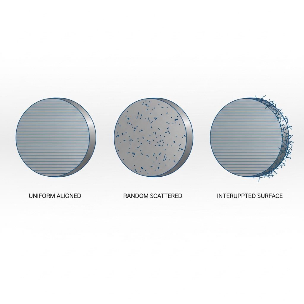
| Grain Structure | Continuous, aligned grain flow following component contours; refined grain size from plastic deformation | Random grain orientation; dendritic structure with non-uniform grain sizes; grain boundary voids common | Grain flow interrupted at machined surfaces; exposed grain ends at surface; retains original stock structure internally |
| Internal Defects | Minimal—compressive forces close voids, eliminate porosity, redistribute inclusions along grain flow lines | Shrinkage cavities, gas porosity, and trapped inclusions common; defect severity depends on casting control but cannot be fully eliminated | Retains any defects from original stock material; no mechanism for defect elimination during manufacturing |
| Surface Integrity | Continuous grain flow to surface; may require finish machining but underlying structure remains intact | Random grain orientation at surface; may have surface porosity or inclusions; requires careful mold surface preparation | Disturbed surface layer from cutting action; exposed grain boundaries; surface residual stresses from machining operations |
| Relative Fatigue Life | Superior—typically 6x to 50x longer life than cast alternatives depending on loading conditions; 36% higher fatigue strength at 10^6 cycles compared to ductile cast iron | Lowest—internal defects serve as crack initiation sites; random grain structure provides easy crack propagation paths | Intermediate—depends heavily on original stock quality; surface grain interruption creates fatigue vulnerability at crack initiation stage |
| Best Use Cases | Fatigue-critical applications; safety components; high-stress connections; cyclic loading environments; aerospace, automotive, and industrial applications demanding maximum reliability | Complex geometries where forging dies are impractical; low-stress applications; components where fatigue is not primary failure mode; cost-sensitive applications with adequate safety factors | Low-volume production; prototype development; non-fatigue-critical components; applications where surface finish requirements exceed what forging provides directly |
Surface finish considerations add another dimension to this comparison. While forged components may require secondary machining to achieve final dimensional tolerances, the underlying grain structure established during forging remains intact beneath the machined surface. The fatigue performance benefits persist because crack initiation typically occurs at or just below the surface—and the refined, continuous grain structure at these critical depths resists crack nucleation.
For metal fatigue resistance methods, the evidence consistently points toward forging as the superior manufacturing approach when cyclic loading determines component life. The combination of defect elimination, grain refinement, and aligned grain flow creates a metallurgical foundation that neither casting nor machining can replicate. Cast components fight an uphill battle against inherent porosity and random grain orientation. Machined components start with whatever defects existed in the stock material and add surface grain interruption during manufacturing.
Understanding these fundamental differences in fatigue performance helps engineers select the right manufacturing method from the start. When component failure carries significant consequences—whether safety-critical aerospace parts, high-performance automotive components, or industrial machinery operating under demanding conditions—the comparative advantages of forging become difficult to ignore. The initial investment in forging tooling and process control pays dividends through extended service life, reduced failure rates, and the confidence that comes from knowing your components possess the best possible metallurgical foundation for resisting fatigue.
Material-Specific Fatigue Improvements Through Forging
You've seen how forging outperforms casting and machining across the board—but here's what many engineers overlook: the degree of fatigue improvement varies significantly depending on which metal you're working with. Steel, aluminum, and titanium each respond differently to the forging process, and understanding these material-specific behaviors helps you maximize fatigue performance for your particular application.
While forging benefits all metals through grain refinement, defect elimination, and aligned grain flow, each material brings unique characteristics that interact with the forging process in distinct ways. Steel alloys experience dramatic work hardening effects. Aluminum gains most from porosity elimination. Titanium requires precise temperature control to optimize its dual-phase microstructure. Let's explore what makes each material special—and how to leverage forging for maximum fatigue resistance.
Steel Alloy Forging for Maximum Fatigue Life
When it comes to forged steel fatigue resistance, steel alloys deliver perhaps the most dramatic improvements from the forging process. Here's why: steel responds exceptionally well to the work hardening and grain refinement that occur during plastic deformation. Every hammer blow or press stroke increases dislocation density within the crystalline structure, creating a stronger, more fatigue-resistant material.
The Hall-Petch relationship we discussed earlier applies powerfully to forged steel. As forging refines grain size—often reducing grains to a fraction of their original dimensions—yield strength increases proportionally. This grain refinement directly translates to higher fatigue limits because smaller grains mean more grain boundaries, and more boundaries mean more barriers to crack propagation.
Steel alloys also benefit from forging's ability to homogenize the microstructure. During solidification of steel ingots, compositional segregation can occur—certain alloying elements concentrate in specific regions rather than distributing uniformly. The intense plastic deformation during forging breaks up these segregated zones, creating a more uniform composition throughout the component. This homogeneity eliminates localized weak spots that could otherwise serve as fatigue crack initiation sites.
For high-performance applications like crankshafts, connecting rods, and gear components, forged steel remains the gold standard precisely because of this combination of work hardening, grain refinement, and compositional homogeneity. The aerospace and automotive industries rely on these characteristics when specifying forged steel for components that must survive millions of stress cycles.
Material-Specific Forging Considerations
Each metal category presents unique opportunities and challenges when optimizing forging parameters for fatigue performance. Understanding these distinctions helps engineers select appropriate materials and forging approaches for specific applications:
-
Steel Alloys
- Work hardening during deformation significantly increases strength and fatigue resistance
- Grain refinement through recrystallization creates uniform, fine-grained structure
- Homogenizes compositional segregation from original casting
- Responds well to post-forge heat treatments for further property optimization
- Wide forging temperature range (850-1150°C) provides process flexibility
- Best suited for: automotive powertrain, aerospace structural components, industrial machinery, high-stress fasteners
-
Aluminum Alloys
- Primary benefit comes from elimination of casting porosity—a common defect in aluminum castings
- Gas porosity from dissolved hydrogen during solidification gets compressed and eliminated during forging
- Lower forging temperatures (around 500°C) require different equipment considerations
- Excellent strength-to-weight ratio makes forged aluminum ideal for weight-sensitive fatigue applications
- Grain refinement improves fatigue resistance while maintaining aluminum's inherent corrosion resistance
- Best suited for: aerospace structural members, automotive suspension components, bicycle frames, marine applications
-
Titanium Alloys
- Fatigue properties critically depend on alpha-beta phase optimization during hot forging
- According to research on titanium forging temperatures, alpha + beta forging (1500-1750°F or 816-954°C) typically yields better fatigue resistance due to finer grain structure and more uniform phase distribution
- Beta transus temperature (typically 1700-1850°F or 927-1010°C) serves as critical control point for microstructure development
- Narrow processing window demands precise temperature control—slight deviations significantly impact properties
- Exceptional strength-to-weight ratio combined with corrosion resistance makes forged titanium ideal for demanding environments
- Best suited for: aerospace engine components, landing gear, biomedical implants, marine propulsion systems
The titanium forging properties deserve special attention because this material's behavior differs substantially from steel and aluminum. Titanium's crystal structure changes at the beta transus temperature—transitioning from a hexagonal close-packed alpha phase to a body-centered cubic beta phase. Controlling whether forging occurs above or below this transition temperature determines the final microstructure and, consequently, fatigue performance.
When titanium undergoes alpha + beta forging below the beta transus, the resulting microstructure consists of primary alpha grains and transformed beta regions. This structure typically delivers the best balance of strength and fatigue resistance. Beta forging above the transus temperature can improve ductility and formability but may sacrifice some fatigue performance due to coarser grain development during cooling.
Material selection for forging ultimately depends on matching material characteristics to application requirements. Steel alloys dominate where maximum strength and fatigue resistance matter most. Aluminum forging benefits applications demanding weight reduction without sacrificing cyclic loading capability. Titanium serves environments requiring exceptional strength-to-weight ratios combined with corrosion resistance and biocompatibility.
Understanding how each material responds to the forging process empowers engineers to specify optimal combinations of material and manufacturing method. The fatigue improvements from forging aren't uniform across all metals—but when you match the right material to the right forging approach, the results speak for themselves through extended component life and reduced failure rates in service.
Industry Applications Where Forging Prevents Fatigue Failure
You've explored how different materials respond to forging—now let's see where these fatigue benefits matter most in the real world. Across industries where component failure isn't just inconvenient but potentially catastrophic, forging has become the manufacturing method of choice. From the suspension arms keeping your vehicle stable during emergency braking to the landing gear absorbing impact forces during aircraft touchdown, forged components quietly prevent disasters every single day.
When engineers evaluate manufacturing options for fatigue-critical applications, they're not just comparing initial costs. They're calculating the total cost of ownership—factoring in failure rates, warranty claims, maintenance intervals, and the consequences when something goes wrong. According to industry analysis from Amfas International, forged parts achieve better dimensional accuracy and operational consistency with fewer weak points, making them indispensable where strength-to-weight ratio, reliability, and performance under extreme stress define success.
Automotive Components That Demand Forged Fatigue Resistance
Imagine driving down the highway when your suspension component suddenly fails. This nightmare scenario explains why automotive forging applications have expanded dramatically as vehicle performance requirements intensify. Modern vehicles experience millions of stress cycles throughout their service life—every bump, turn, acceleration, and braking event places cyclic loads on critical components.
The automotive industry relies on forging for components where fatigue failure simply cannot be tolerated:
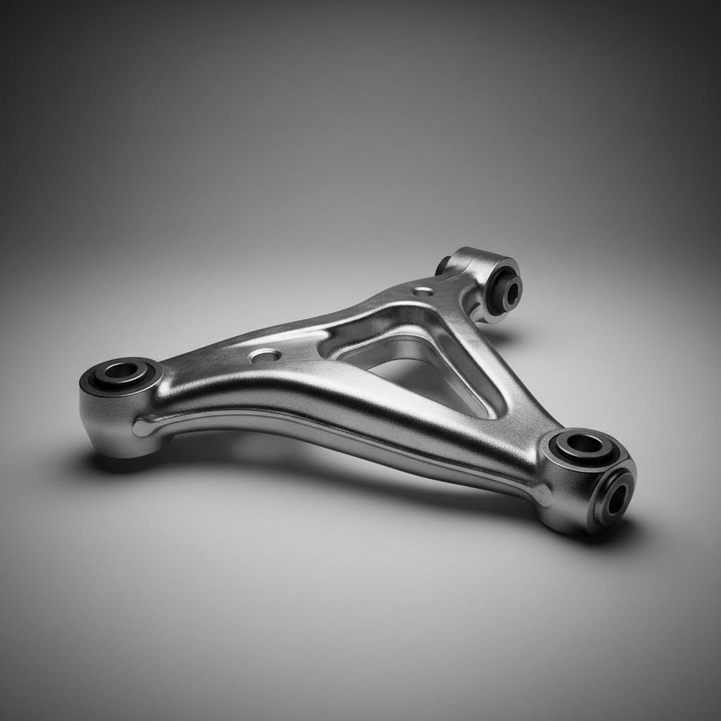
- Suspension Arms and Control Arms — These components endure constant cyclic loading from road irregularities while maintaining precise wheel geometry. Forged suspension arms resist crack initiation at stress concentration points and provide the directional strength needed to handle both vertical impacts and lateral cornering forces. The continuous grain flow in forged arms follows the component contours, placing maximum fatigue resistance exactly where stresses concentrate.
- Connecting Rods — Operating in the extreme environment of internal combustion engines, connecting rods experience alternating tensile and compressive loads thousands of times per minute. Each combustion event creates an explosive force that the rod must transmit from piston to crankshaft. Forged connecting rods withstand this punishing cyclic loading through refined grain structure and elimination of internal defects that would otherwise initiate fatigue cracks.
- Crankshafts — Perhaps no automotive component faces more severe fatigue demands. Crankshafts convert the reciprocating motion of pistons into rotational power while enduring torsional vibrations, bending moments, and high-frequency stress reversals. The aligned grain flow in forged crankshafts provides exceptional resistance to the multi-axial fatigue loading that destroys lesser components.
- Drive Shafts and Axle Shafts — These torque-transmitting components experience fluctuating loads during acceleration, deceleration, and gear changes. Upset-forged ends create reinforced connection points where splines and flanges meet mating components—the exact locations where fatigue cracks would otherwise initiate under cyclic torque loading.
- Steering Knuckles and Wheel Hubs — Safety-critical steering and wheel mounting components must survive the combined effects of road loads, braking forces, and cornering stresses throughout the vehicle's entire service life.
For automotive engineers sourcing fatigue-critical components, working with precision hot forging solutions from certified manufacturers ensures consistent quality. Suppliers like Shaoyi (Ningbo) Metal Technology deliver IATF 16949-certified automotive components including forged suspension arms and drive shafts, with in-house engineering ensuring fatigue-critical specifications are met from design through production.
Critical Applications Across Industries
Beyond automotive, several industries depend on forging's fatigue benefits where component failure carries consequences far more severe than inconvenience or warranty costs.
Aerospace Applications
When you're flying at 35,000 feet, there's no pulling over to the side of the road. Aerospace forged components face the industry's most stringent fatigue requirements because failure often means loss of life. The cyclic pressurization of aircraft fuselages, the repeated loading cycles during takeoff and landing, and the vibration environments of turbine engines all demand exceptional fatigue resistance.
- Landing Gear Components — These assemblies absorb tremendous impact energy during every landing while supporting the full weight of the aircraft during ground operations. Forged landing gear components provide the impact resistance and fatigue strength needed to survive thousands of landing cycles. The energy absorption capacity of forged components allows them to withstand sudden shocks without fracturing—critical for aerospace landing gear.
- Turbine Disks and Blades — Operating at high temperatures while spinning at thousands of RPM, turbine components experience extreme centrifugal forces combined with thermal cycling. Forged turbine disks benefit from refined grain structure optimized for high-temperature fatigue resistance.
- Structural Fittings and Brackets — The airframe components connecting major structural elements must maintain integrity throughout decades of service despite continuous cyclic loading from flight maneuvers, gusts, and pressurization cycles.
Heavy Machinery and Industrial Applications
Industrial equipment operates under conditions that would quickly destroy components manufactured through less robust methods. The combination of heavy loads, continuous operation, and demanding environments makes forging essential for equipment reliability.
- Crane Hooks and Lifting Equipment — A crane hook failure during a lift can result in catastrophic consequences including equipment destruction, facility damage, and loss of life. Forged crane hooks handle extreme loads and the shock loading that occurs during lifting operations.
- Railroad Wheels and Axles — Rail components experience repetitive impact loading from rail joints combined with heavy axle loads. Forged railroad components must survive millions of wheel rotations while maintaining dimensional stability and crack resistance.
- Mining Equipment Components — Operating in abrasive, high-vibration environments with minimal opportunity for maintenance, mining equipment demands forged components that resist fatigue under the harshest possible conditions.
Oil and Gas Applications
The oil and gas industry operates in environments where component failure can trigger explosions, environmental disasters, and production losses measured in millions of dollars per day. Forging delivers the reliability these applications demand.
- High-Pressure Valves and Flanges — These components experience pressure cycling from operational demands while potentially facing corrosive environments. Forged valves withstand the combined effects of fatigue loading and environmental attack.
- Drilling Components — Downhole drilling equipment faces extreme pressure, temperature, and vibration while operating miles below the surface where replacement is extraordinarily difficult and expensive.
- Subsea Equipment — Components operating on the ocean floor must provide reliable service for decades with zero opportunity for maintenance access.
The Economic Justification
When evaluating forging versus alternatives, the initial cost tells only part of the story. Smart procurement decisions consider total cost of ownership across the component's entire service life. Forged components typically deliver:
- Reduced Failure Rates — Fewer in-service failures mean less unplanned downtime, reduced emergency repair costs, and avoided consequential damages from component failures.
- Extended Service Life — Components lasting longer between replacements reduce lifecycle costs even when initial purchase prices exceed alternatives.
- Decreased Warranty Claims — For OEMs, reduced warranty exposure directly impacts profitability while building brand reputation for reliability.
- Lower Inspection Requirements — Higher confidence in forged component integrity can reduce inspection frequency and associated maintenance costs.
- Safety Margin Benefits — Superior fatigue resistance provides additional safety margins that may enable design optimization or weight reduction in surrounding structures.
The industries discussed here share a common characteristic: they cannot afford to gamble with component reliability. Whether the application involves passenger vehicles, commercial aircraft, industrial machinery, or energy infrastructure, the consequences of fatigue failure extend far beyond simple replacement costs. This reality explains why forging continues expanding into new applications as engineers increasingly recognize that superior fatigue resistance during manufacturing prevents catastrophic failures during service.
Understanding where forging delivers maximum value helps engineers specify the right manufacturing approach from the start—but validating that fatigue performance requires standardized testing methods and robust quality assurance systems.
Testing Standards and Quality Assurance for Fatigue Performance
How do you verify that forged components actually deliver the fatigue performance you're counting on? Claims about superior grain structure and defect elimination sound compelling—but engineering decisions require objective validation. This is where standardized testing methods and rigorous quality control measures transform theoretical advantages into documented, repeatable performance data.
The good news? Well-established ASTM fatigue testing standards provide systematic approaches for measuring exactly how materials and components behave under cyclic loading. These methods enable apples-to-apples comparisons between manufacturing approaches while giving engineers the confidence to specify forged components for fatigue-critical applications.
Industry Standards for Fatigue Validation
Several internationally recognized standards govern fatigue testing, each designed for specific loading conditions and material behaviors. Understanding which standard applies to your application ensures meaningful test results that predict real-world performance.
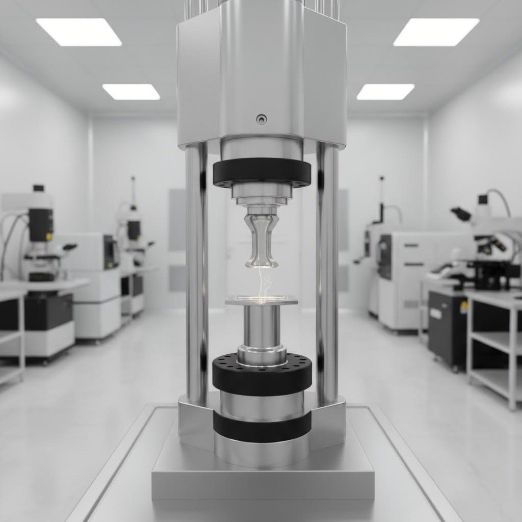
According to TestResources' analysis of fatigue testing methodology, ASTM E466 provides a systematic approach for fatigue testing of metallic materials under constant amplitude loading at ambient temperature. This standard specifically measures fatigue strength of unnotched and notched axial specimens where strains remain predominantly elastic throughout testing—conditions that characterize many high-cycle fatigue applications.
The standard emphasizes controlling nuisance variables like hardness, grain size, and surface finish to ensure comparable fatigue data across laboratories. This attention to consistency matters enormously when comparing forged components against cast or machined alternatives—you need confidence that observed performance differences stem from manufacturing method rather than testing variations.
| Standard | Test Type | What It Measures | Application |
|---|---|---|---|
| ASTM E466 | Axial fatigue testing (force-controlled) | Fatigue strength under constant amplitude cyclic loading; S-N curve development for high-cycle fatigue regime | Components experiencing predominantly elastic strain; high-cycle applications exceeding 10,000 cycles; comparing material fatigue resistance across manufacturing methods |
| ASTM E606 | Strain-controlled fatigue testing | Low-cycle fatigue behavior; strain-life relationships; cyclic stress-strain response | Components experiencing significant plastic strain; low-cycle fatigue applications under 10,000 cycles; thermal cycling environments; pressure vessel components |
| ISO 1143 | Rotating beam fatigue testing | Fatigue limit under rotating bending; endurance characteristics of metallic materials | Shaft and axle applications; components experiencing rotating bending loads; establishing baseline material fatigue properties |
| ASTM E647 | Fatigue crack growth rate testing | Rate of crack propagation under cyclic loading; threshold stress intensity for crack growth | Damage tolerance analysis; remaining life predictions for components with detected flaws; validating grain flow benefits on crack resistance |
The S-N curve generated from ASTM E466 testing serves as a fundamental tool for comparing forging's fatigue benefits against alternatives. This curve plots cyclic stress amplitude against the number of cycles until failure, typically on a logarithmic scale. When forged and cast components undergo identical testing protocols, the forged specimens consistently demonstrate superior performance—often surviving significantly more cycles at equivalent stress levels, or tolerating higher stresses for equivalent cycle counts.
Quality Control Measures That Ensure Consistency
Testing validates performance—but consistent fatigue properties require forging quality control throughout the manufacturing process. Several critical parameters demand monitoring and control to ensure every component achieves the metallurgical characteristics that deliver superior fatigue resistance.
Temperature Monitoring — Forging temperature directly affects grain refinement, material flow, and final microstructure. Too low, and the metal may crack during deformation. Too high, and excessive grain growth can compromise fatigue properties. Continuous temperature monitoring using thermocouples, infrared pyrometers, or thermal imaging ensures material remains within optimal ranges throughout the forging sequence.
Deformation Control — The degree and rate of plastic deformation determine grain refinement and internal defect elimination. Precise control of press forces, hammer energy, and die closure ensures consistent material flow and grain structure development across production runs. Modern forging operations often employ real-time force monitoring to verify each component receives appropriate deformation.
Post-Forge Inspection — After forging, components undergo inspection to verify dimensional conformance and internal integrity. This inspection includes both dimensional verification and non-destructive testing to detect any anomalies that could compromise fatigue performance.
Non-destructive testing methods—collectively known as forging inspection techniques—verify internal integrity without damaging the component:
- Ultrasonic Testing (UT) — High-frequency sound waves detect internal voids, inclusions, and discontinuities that could serve as fatigue crack initiation sites. UT provides volumetric inspection capability for verifying that forging has eliminated the internal defects common in cast materials.
- Magnetic Particle Inspection (MPI) — For ferromagnetic materials, MPI detects surface and near-surface discontinuities by magnetizing the component and applying magnetic particles that congregate at defect locations.
- Dye Penetrant Inspection (DPI) — Surface-breaking defects become visible when penetrant dye enters cracks and flaws, then bleeds out onto a developer coating. This method verifies surface integrity critical for fatigue crack initiation resistance.
- Radiographic Testing — X-ray or gamma-ray imaging reveals internal defects, porosity, and inclusions—providing documented evidence of internal quality for critical applications.
The combination of standardized fatigue testing methods and comprehensive quality control creates a verification framework that transforms forging's theoretical advantages into documented, repeatable performance. When engineers specify forged components for fatigue-critical applications, this testing and inspection infrastructure provides confidence that each component will deliver the expected service life—backed by objective data rather than assumptions.
With testing standards establishing performance baselines and quality systems ensuring manufacturing consistency, the remaining question becomes practical: when does forging make sense for your specific application, and how do you partner effectively with forging suppliers to optimize your designs?
Making Informed Decisions About Forging for Fatigue Applications
You've seen the compelling evidence for forging's fatigue advantages—but here's what separates good engineering from great engineering: knowing when forging is the right choice and when alternatives might actually serve you better. Blindly specifying forged components for every application wastes resources, while overlooking forging where it matters risks premature failures. The key lies in objectively evaluating your specific requirements against forging's capabilities and limitations.
Let's be honest: forging isn't always the answer. According to manufacturing process analysis from Frigate, ignoring forging's limitations can lead to costly production mistakes, delays, and poor-quality products. Understanding these boundaries helps you make smarter decisions about whether forging fits your project—or whether alternative approaches might deliver better results.
Evaluating When Forging Is the Right Choice
Before committing to forging, consider several critical factors that determine whether this manufacturing method aligns with your application requirements. Not every component benefits equally from forging's advantages, and some designs simply cannot be economically produced through forging processes.
Geometry Complexity Constraints — Forging excels at producing components with relatively straightforward shapes, but complex geometries present significant challenges. Parts featuring sharp corners, asymmetrical designs, or intricate internal features can disrupt grain flow—the very characteristic that makes forging superior for fatigue resistance. When grain flow becomes uneven due to geometric complexity, the fatigue benefits diminish substantially. If your component requires features that exceed practical forging capabilities, consider whether machining from forged stock or alternative manufacturing methods might prove more effective.
Production Volume Economics — Forging requires dies—special molds subjected to immense pressure during each forming operation. Creating these dies represents significant upfront investment, with die maintenance and replacement potentially accounting for up to 20% of overall production costs in precision applications. For low-volume production runs or one-off prototypes, this tooling investment may not justify itself. However, for high-volume applications where tooling costs amortize across thousands of components, forging's per-piece economics become increasingly attractive.
When Alternative Methods Suffice — Not every component experiences fatigue loading severe enough to warrant forging's premium. For applications where static loading dominates, where safety factors provide ample margin, or where surface treatments can compensate for base material limitations, casting or machining combined with appropriate post-processing may deliver acceptable performance at lower cost. The question becomes: how fatigue-critical is your application really?
Consider these decision criteria when evaluating forging vs other manufacturing approaches for your specific application:
- Fatigue Criticality Assessment — Does component failure create safety hazards, significant downtime costs, or warranty exposure? High-consequence applications strongly favor forging despite higher initial costs.
- Expected Stress Cycles — Components experiencing millions of loading cycles throughout service life benefit most from forging's crack resistance. Low-cycle applications may tolerate alternative manufacturing methods.
- Stress Concentration Locations — Can forging dies be designed to optimize grain flow at critical stress points? If geometry prevents beneficial grain orientation, forging's advantages diminish.
- Production Volume and Frequency — Will volumes justify die investment? Consider both initial production and anticipated replacement or spare parts requirements over the product lifecycle.
- Material Availability and Cost — Some materials forge more easily than others. Exotic alloys with narrow processing windows may require specialized forging expertise that limits supplier options.
- Dimensional Tolerance Requirements — Forging produces near-net shapes, but precision tolerances typically require secondary machining. Factor finishing operations into total manufacturing cost comparisons.
- Lead Time Constraints — Die design and manufacturing require time. If urgent prototype development drives your schedule, when to use forging may depend on supplier capabilities for rapid tooling.
Working with Forging Partners for Optimal Results
Even after determining that forging suits your application, success depends heavily on forging supplier selection and collaborative design optimization. Experienced forging partners bring expertise that transforms good designs into exceptional forged components—while identifying potential problems before they become expensive production issues.
According to design optimization research from Bunty LLC, it's essential to consult with an experienced metal parts manufacturer who understands design principles and manufacturing processes. They can help you choose the most suitable optimization methods for your specific project and ensure the best possible outcome for your components.
Design for Manufacturing (DFM) principles apply directly to forging. The goal is simplifying designs so components can be manufactured quickly and cost-effectively without compromising quality. For forging applications, DFM considerations include:
- Draft Angles — Appropriate draft angles enable component removal from dies without damage or excessive wear.
- Fillet Radii — Generous fillets promote smooth material flow and reduce stress concentrations in the finished component.
- Parting Line Location — Strategic parting line placement minimizes flash removal challenges and positions grain flow optimally.
- Wall Thickness Uniformity — Consistent sections promote uniform cooling and reduce residual stress development.
The best forging partnerships combine supplier expertise with early design involvement. Rather than presenting finished designs and asking for quotes, engage potential suppliers during concept development. Their input on forging design optimization can eliminate manufacturability problems while enhancing fatigue performance through grain flow improvements you might not have considered.
For engineers evaluating forging feasibility quickly, manufacturers with rapid prototyping capabilities—some delivering prototypes in as few as 10 days—enable practical evaluation before committing to production tooling. Geographic considerations matter too: suppliers located near major shipping hubs like Ningbo Port can compress delivery timelines for global supply chains.
When assessing potential forging partners, consider their engineering support capabilities alongside manufacturing credentials. Suppliers like Shaoyi (Ningbo) Metal Technology offer in-house engineering support for design optimization, helping engineers evaluate whether forging suits their specific requirements while identifying opportunities to improve fatigue performance through design refinements.
The decision to forge—or pursue alternatives—ultimately requires balancing fatigue requirements against practical constraints. When you approach this decision systematically, evaluate your specific loading conditions honestly, and partner with suppliers who prioritize your success over simply winning orders, you'll consistently arrive at manufacturing decisions that deliver reliable, cost-effective components for your most demanding applications.
Frequently Asked Questions About Forging and Metal Fatigue
1. How does forging improve fatigue behavior compared to other manufacturing methods?
Forging improves fatigue behavior through three key mechanisms: continuous grain flow alignment that forces cracks to travel across grain boundaries rather than along them, elimination of internal voids and porosity through compressive forces, and refined grain structure that increases resistance to crack initiation. Research shows forged steel components can achieve 36% higher fatigue strength at 10^6 cycles compared to ductile cast iron, with fatigue life improvements of 6x to 50x depending on loading conditions.
2. What are the disadvantages of forging metal?
Forging has several limitations engineers should consider. It cannot produce porous bearings, sintered carbides, or parts with multiple metal compositions. Complex geometries with sharp corners or intricate internal features may disrupt beneficial grain flow. Die production requires significant upfront investment, making short production runs economically challenging. Additionally, small, finely designed parts typically require secondary machining operations to achieve final specifications.
3. Can metal fatigue be reversed or eliminated?
Metal fatigue damage is generally irreversible once cracks have initiated. Simply bending a fatigued component back does not restore its original strength. The only way to truly eliminate accumulated fatigue damage is to reheat the metal to temperatures where atoms can move freely and then re-cool it—essentially re-smelting the material. This is why preventing fatigue through proper manufacturing methods like forging is far more effective than attempting to address it after damage occurs.
4. What is upset forging and when should it be used?
Upset forging is a process where compressive forces increase cross-sectional area at specific locations while maintaining overall component length. It's ideal for components requiring localized material buildup at stress concentration points—such as bolt heads, valve stems, and automotive drive shaft ends. Upset forging concentrates refined grain structure exactly where fatigue loading is most severe, making it superior for fasteners, flanged fittings, and axle spindles experiencing cyclic stress at connection points.
5. How do manufacturers verify fatigue performance of forged components?
Manufacturers use standardized testing methods including ASTM E466 for axial fatigue testing, ASTM E606 for strain-controlled testing, and ISO 1143 for rotating beam tests. Quality control during forging includes temperature monitoring, deformation control, and post-forge inspection. Non-destructive testing methods such as ultrasonic testing, magnetic particle inspection, and dye penetrant inspection verify internal integrity. IATF 16949-certified manufacturers like Shaoyi ensure consistent fatigue properties through rigorous process control and documentation.