 Small batches, high standards. Our rapid prototyping service makes validation faster and easier —

Custom Forging Tolerances Explained: 8 Costly Mistakes Buyers Make

What Forging Tolerances Really Mean for Your Components
When you order a custom forged component, how do you know if it will actually fit your assembly? The answer lies in understanding forging tolerances - the hidden specifications that determine whether your parts work flawlessly or cause costly failures down the line.
Forging tolerances define the permissible variation from specified dimensions in forged components. Think of them as the acceptable margin of error between what you design and what the manufacturing process can realistically deliver. No matter how precise the equipment or process, some variation is inevitable when shaping metal under extreme pressure and temperature.
Forging tolerance is the allowable deviation in dimensions, shape, and surface finish of a forged part from its nominal specifications while still ensuring the component meets functional requirements.
Why should you care? Because getting tolerances wrong leads to parts that don't fit properly, assemblies that fail prematurely, and projects that blow past budget. Engineers specifying parts and procurement professionals ordering forgings both need to speak the same tolerance language - otherwise, miscommunication becomes expensive.
What Are Forging Tolerances and Why Do They Matter
Imagine ordering a forged shaft with a specified diameter of 50 mm. Without tolerance specifications, how would you know if receiving a 49.5 mm or 50.5 mm shaft is acceptable? According to industry standards, a dimensional tolerance of ±0.5 mm would mean either size works perfectly fine. But if your application requires a precision fit, that variation could spell disaster.
Tolerances matter because they directly impact:
- Interchangeability - Parts must fit with mating components across production runs
- Functionality - Proper fits and tolerances ensure mechanical systems operate correctly
- Safety - Critical applications in aerospace, automotive, and medical industries demand precise tolerance control
- Cost - Tighter tolerances require more precise manufacturing, increasing production expenses
The tolerance fit between components determines everything from how smoothly a bearing rotates to whether a piston seals properly in its cylinder. Get it wrong, and you'll face leaks, excessive wear, or complete assembly failure.
The Three Categories of Forging Tolerances You Must Understand
When reviewing forging specifications, you'll encounter three distinct tolerance categories. Understanding each one prevents the common mistake of focusing only on size while ignoring equally critical shape and surface requirements.
Dimensional Tolerances represent the most fundamental category. These specifications control the physical measurements - length, width, height, diameter, and thickness. For example, general tolerances for linear dimensions typically range from ±0.1 mm for dimensions up to 25 mm to ±0.5 mm for dimensions up to 1200 mm. Every forged part begins with dimensional tolerance specifications that define acceptable size variations.
Geometric Tolerances go beyond simple measurements to control the shape and orientation of features. These specifications address straightness, flatness, roundness, and positional relationships between features. A forged shaft might need a geometric tolerance allowing straightness deviation of only 0.02 mm per meter of length to ensure it functions properly with mating bearings. The tolerance of fit between assembled components often depends more on geometric accuracy than raw dimensions.
Surface Finish Tolerances define the allowable variations in surface texture and roughness. These specifications become critical when forged parts must move against each other, require specific aesthetic appearances, or need proper sealing surfaces. Surface roughness values like Ra 1.6 μm indicate the average height of surface irregularities - essential information when friction minimization or seal integrity matters.
Each category serves a distinct purpose. Missing any one of them in your specifications creates gaps that manufacturers must fill with assumptions - and assumptions rarely align with your actual requirements.
Tolerance Ranges Across Different Forging Methods
Not all forging methods deliver the same dimensional accuracy. When you select a forging process, you're also choosing the tolerance capabilities that come with it. Understanding these differences upfront prevents the frustrating discovery that your chosen method simply cannot achieve the specifications your application demands.
The forging design you create must account for the inherent precision limits of each process. A forging drawing intended for open-die production requires fundamentally different tolerance expectations than one designed for precision closed-die operations. Let's break down what each method can realistically deliver.
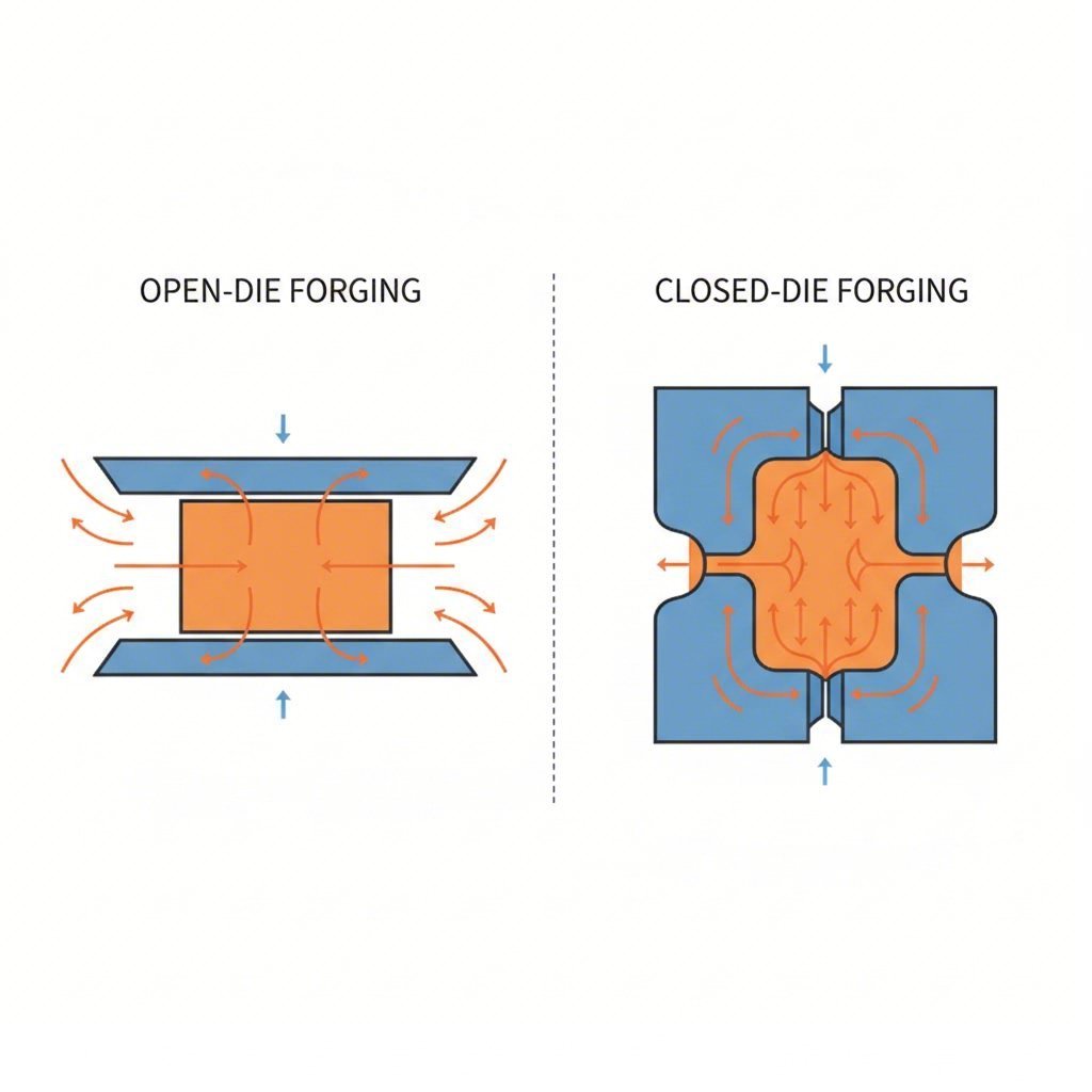
Open-Die vs Closed-Die Tolerance Capabilities
Open-die forging compresses heated metal between flat or minimally contoured dies that don't fully enclose the material. Because the metal flows freely under pressure, dimensional control becomes challenging. Skilled operators manipulate the workpiece through multiple strikes, but this manual process introduces variability that limits achievable tolerances.
According to industry specifications, open-die forging excels at producing large, simple shapes with excellent mechanical properties - but precision isn't its strength. Typical dimensional tolerances for open-die forgings range from ±3 mm to ±10 mm depending on part size and complexity. You'll commonly see this method used for shafts, rings, and blocks where subsequent machining will establish final dimensions.
Closed-die forging, also called impression die forging, shapes metal within specifically designed dies that create a cavity matching the desired component shape. The material is compressed under high pressure, causing it to flow and completely fill the die cavity. This confinement produces significantly tighter tolerances than open-die methods.
Why does closed-die achieve better precision? Three key factors:
- Controlled material flow - Dies constrain metal movement to predetermined paths
- Consistent pressure distribution - Enclosed cavities apply uniform force across the workpiece
- Repeatable geometry - Once dies are properly manufactured, every part replicates the same form
The European Standard BS EN 10243-1 establishes two tolerance grades for steel die forgings: Grade F for standard accuracy and Grade E for closer tolerances. For a 5.35 kg gear forging, Grade F tolerances allow width dimensions of +1.9/-0.9 mm, while Grade E tightens this to +1.2/-0.6 mm. This standardized framework helps both buyers and manufacturers speak the same tolerance language.
How Precision Forging Achieves Tighter Specifications
Precision forging represents the next evolution in tolerance capability. This process uses carefully controlled parameters - temperature, pressure, die design, and material preparation - to produce components requiring minimal or no subsequent machining.
What makes precision forging different? The process often incorporates warm or cold working temperatures rather than traditional hot forging. Lower temperatures reduce thermal expansion effects and minimize the dimensional changes that occur during cooling. Additionally, precision forging typically uses more sophisticated die materials and surface treatments that resist wear, maintaining tight tolerances across longer production runs.
Rolled ring forging occupies its own niche in the tolerance spectrum. This specialized process produces seamless rings by piercing a billet and then rolling it between shaped dies. The continuous rolling action creates exceptional grain structure alignment and can achieve fit tolerances suitable for bearing races, gear blanks, and pressure vessel flanges. Diameter tolerances typically range from ±1 mm to ±3 mm depending on ring size, with wall thickness variations controlled to similar ranges.
| Method Type | Typical Dimensional Tolerance Range | Best Applications | Relative Cost Impact |
|---|---|---|---|
| Open-Die Forging | ±3 mm to ±10 mm | Large shafts, blocks, custom shapes requiring machining | Lower tooling cost; higher per-part finishing cost |
| Closed-Die Forging (Grade F) | ±0.9 mm to ±3.7 mm | High-volume automotive parts, connecting rods, gears | Moderate tooling investment; economical at volume |
| Closed-Die Forging (Grade E) | ±0.5 mm to ±2.4 mm | Precision components, crankshafts, critical assemblies | Higher tooling and process cost; reduced machining |
| Precision Forging | ±0.2 mm to ±0.5 mm | Net-shape components, aerospace parts, medical devices | Highest tooling cost; minimal post-processing |
| Rolled Ring Forging | ±1 mm to ±3 mm | Bearing races, flanges, gear blanks, pressure vessel rings | Specialized equipment; cost-effective for ring geometries |
Several technical factors explain why different methods achieve different tolerance levels. Die wear patterns play a significant role - open dies experience uneven wear from varied workpiece contact, while closed dies wear more predictably but still require monitoring. The BS EN 10243-1 standard explicitly notes that tolerances account for die wear alongside shrinkage variations.
Material flow characteristics also influence achievable precision. In closed-die forging, metal flowing into thin sections or complex branches causes more dimensional variation than simple compact shapes. The standard addresses this through shape complexity factors ranging from S1 (simple shapes with factor above 0.63) to S4 (complex shapes with factor up to 0.16). More complex geometries receive larger tolerance allowances.
Temperature effects compound these challenges. Hot forging temperatures create thermal expansion during forming followed by contraction during cooling. Predicting exact shrinkage requires accounting for alloy composition, cooling rate, and part geometry. High-alloy steels with carbon content above 0.65% or total alloying elements above 5% receive different tolerance classifications than standard carbon steels - recognizing their more difficult forming characteristics.
Choosing the right forging method means balancing tolerance requirements against cost realities. Specifying precision forging tolerances for parts that will undergo extensive machining wastes money. Conversely, selecting open-die forging for components requiring tight fit tolerances guarantees expensive secondary operations. The key lies in matching method capabilities to actual functional requirements.
Fit Types and Their Tolerance Requirements
You've selected your forging method and understand what tolerance ranges to expect. But here's where many buyers stumble: specifying how the forged component will actually mate with other parts in the assembly. The slip fit tolerance you need for a rotating shaft differs dramatically from the tolerance interference fit required for a permanently mounted gear hub.
Fits describe the dimensional relationship between mating parts - typically a shaft and hole combination. According to ANSI B4.1 standards, fits are categorized into three general groups: running or sliding fits (RC), locational fits (LC, LT, LN), and force or shrink fits (FN). Each category serves distinct functional purposes in forging applications.
Understanding Slip Fit and Clearance Fit Requirements
When your forged components need to move freely against mating parts, clearance fit tolerance specifications become essential. A clearance fit always leaves room between the shaft and hole, enabling easy assembly and allowing sliding or rotational movement during operation.
Sounds straightforward? Here's where it gets interesting. The ANSI B4.1 standard defines nine classes of running and sliding fits, each designed for specific operating conditions:
- RC 1 - Close Sliding Fit: Intended for accurate location of parts that must assemble without perceptible play. Use this for precision forged guide components requiring exact positioning.
- RC 2 - Sliding Fit: Provides accurate location with greater maximum clearance than RC 1. Parts move and turn easily but are not intended to run freely. Larger sizes may seize with small temperature changes.
- RC 3 - Precision Running Fit: About the closest fits that can run freely. Ideal for precision forged parts at slow speeds and light pressures, but avoid where temperature differences are likely.
- RC 4 - Close Running Fit: Designed for accurate machinery with moderate surface speeds and journal pressures where accurate location and minimum play are desired.
- RC 5 and RC 6 - Medium Running Fit: Intended for higher running speeds or heavy journal pressures. Common for forged shafts in industrial equipment.
- RC 7 - Free Running Fit: Use where accuracy is not essential or where large temperature variations are expected. Suitable for loose forged assemblies.
- RC 8 and RC 9 - Loose Running Fit: Allow wide commercial tolerances with an allowance on the external member. Best for non-critical forged components.
For example, using a 2-inch nominal diameter with an RC 5 fit, the maximum hole becomes 2.0018 inches while the minimum shaft measures 1.9963 inches. This creates a minimum clearance of 0.0025 inches and maximum clearance of 0.0055 inches - enough room for higher running speeds while maintaining reasonable precision.
Locational clearance fits (LC) serve a different purpose. According to engineering fit standards, these fits determine only the location of mating parts for components that are normally stationary but can be freely assembled or disassembled. They range from snug fits for accuracy to looser fastener fits where freedom of assembly is paramount.
When to Specify Interference and Press Fit Tolerances
Imagine a forged gear hub that must permanently transmit rotational power without any relative movement. This is where interference fits become essential. With tolerance interference fit specifications, the shaft is always slightly larger than the hole, requiring force, heat, or both to create the assembly.
The ANSI B4.1 standard categorizes force fits (FN) by the level of interference required:
- FN 1 - Light Drive Fit: Requires light assembly pressures and produces more or less permanent assemblies. Suitable for thin sections, long fits, or cast-iron external members.
- FN 2 - Medium Drive Fit: Appropriate for ordinary steel parts or shrink fits on light sections. About the tightest fits usable with high-grade cast-iron external members.
- FN 3 - Heavy Drive Fit: Designed for heavier steel parts or shrink fits in medium sections.
- FN 4 and FN 5 - Force Fit: Suitable for parts that can be highly stressed or for shrink fits where heavy pressing forces required are impractical.
Press fit tolerancing maintains constant bore pressures throughout the range of sizes. The interference varies almost directly with diameter, keeping resulting pressures within reasonable limits. Using a 25 mm diameter with an H7/s6 fit, you'll see minimum interference of 0.014 mm and maximum interference of 0.048 mm - requiring either cold pressing with significant force or hot pressing techniques.
Transition fits (LT) occupy the middle ground. A forged part specified with a transition fit may end up with slight clearance or slight interference - both outcomes are acceptable. This flexibility works well for applications where accuracy of location matters but either a small amount of clearance or interference is permissible. Assembly typically requires only a rubber mallet or light force.
| Fit Type | Tolerance Characteristic | Common Forging Applications |
|---|---|---|
| Clearance Fit (RC/LC) | Shaft always smaller than hole; clearance ranges from 0.007 mm to 0.37 mm depending on class and size | Forged shafts with plain bearings, sliding rods, machine tool spindles, pivots and latches |
| Sliding Fit | Minimal clearance allowing free movement with lubrication; H7/h6 provides 0.000 to 0.034 mm clearance | Forged roller guides, guiding shafts, clutch discs, slide valves |
| Transition Fit (LT) | May result in slight clearance or slight interference; H7/k6 yields +0.019 mm clearance to -0.015 mm interference | Forged hubs, gears on shafts, pulleys, armatures, driven bushes |
| Press Fit (FN 1-2) | Light to medium interference; H7/p6 provides 0.001 to 0.035 mm interference requiring cold pressing | Forged bearing housings, bushings, light-duty gear mounts |
| Interference Fit (FN 3-5) | Heavy interference; H7/u6 provides 0.027 to 0.061 mm interference requiring heating/freezing | Forged permanent gear assemblies, heavy-duty shaft connections, high-torque applications |
When communicating fit requirements to forging manufacturers, clarity prevents costly mistakes. Don't assume your supplier understands the intended application - state it explicitly. Include these elements in your specifications:
- Mating part details: Describe what the forged component will connect with, including material and condition
- Functional requirements: Explain whether parts must rotate, slide, remain permanently fixed, or be removable
- Tolerance class designation: Use standard ANSI or ISO fit designations (H7/g6, RC4, etc.) rather than just "tight" or "loose"
- Critical surfaces: Identify which surfaces require fit tolerance control versus general tolerance acceptance
- Assembly method: Specify if hot pressing, cold pressing, or hand assembly is intended
Remember that as-forged surfaces rarely achieve the precision needed for critical fits. Your specification should clarify whether the stated tolerance for slip fit or interference applies to the as-forged condition or to machined surfaces. This distinction determines both cost and manufacturing sequence - topics that directly connect to temperature effects on achievable tolerances.
Temperature Effects on Achievable Tolerances
You've specified your fit requirements and understand how different forging methods impact precision. But here's a factor that many buyers overlook until it's too late: the temperature at which your component is forged fundamentally determines what tolerances are even possible.
Think about it this way. Metal expands when heated and contracts when cooled. A steel billet forged at 2,200°F will physically shrink as it returns to room temperature. Predicting exactly how much shrinkage occurs - and controlling it consistently across production runs - becomes the core challenge of tolerance fitting in any forging operation.
How Temperature Affects Dimensional Accuracy
When metal heats above its recrystallization temperature, something remarkable happens. The crystalline grain structure becomes malleable, allowing material to flow and reshape under pressure. According to forging industry research, hot forging temperatures typically range from 1,100°F to 2,400°F depending on the material - temperatures where steel glows bright orange to yellow.
This malleability comes with a trade-off. Thermal expansion during forming means the workpiece is physically larger than its final dimensions. As the part cools, contraction occurs unevenly based on section thickness, cooling rate, and alloy composition. A thick section cools slower than a thin flange, creating differential shrinkage that distorts the final geometry.
Material flow behavior also changes dramatically with temperature. Hot metal moves more freely into die cavities, filling complex shapes completely. But this same fluidity makes precise dimensional control difficult - the material "wants" to flow wherever pressure directs it, sometimes creating flash or overfill in unintended areas.
Die life considerations add another layer of complexity. Hot forging subjects dies to extreme thermal cycling. Each forging operation heats the die surface, then cooling occurs before the next cycle. This repeated expansion and contraction causes die wear patterns that gradually alter part dimensions. Manufacturers must account for this progressive change when maintaining tolerances across long production runs.
Cold Forging vs Hot Forging Tolerance Trade-offs
Cold forging operates at or near room temperature - typically below the metal's recrystallization point. According to precision forging specifications, this approach produces high precision and tight tolerances with superior surface finish compared to hot methods.
Why does cold forging achieve better dimensional accuracy? Without thermal expansion effects, what you forge is essentially what you get. The metal retains its room-temperature dimensions throughout the process, eliminating the shrinkage prediction challenge entirely.
Cold Forging Tolerance Advantages:
- Achieves tight tolerances without secondary machining - dimensional accuracy often reaches ±0.1 mm to ±0.25 mm
- Produces excellent surface finish, frequently eliminating polishing requirements
- Minimal material waste due to controlled, predictable shaping
- Enhanced material strength through strain hardening during deformation
- Better consistency across production runs since thermal variables are eliminated
Cold Forging Tolerance Limitations:
- Limited to simpler shapes - complex geometries may not form completely
- Restricted material selection - aluminum, brass, and low-carbon steel work best
- Higher forming forces required, demanding more robust tooling
- Work hardening can cause brittleness in certain applications
- Part size constraints - very large components exceed equipment capabilities
Hot forging tells a different story. The elevated temperatures enable production of intricate and large-scale components that cold methods simply cannot achieve. Industry comparisons show hot forging accommodates difficult-to-form metals like titanium and stainless steel while producing components with exceptional toughness.
Hot Forging Tolerance Advantages:
- Enables complex shapes and larger components impossible with cold methods
- Wide material compatibility including high-alloy steels and superalloys
- Relieves internal stresses, improving structural integrity
- Refines grain structure for enhanced impact resistance
- Lower forming forces reduce tooling stress and equipment requirements
Hot Forging Tolerance Limitations:
- Requires more generous tolerances - typically ±0.5 mm to ±3 mm depending on size
- Surface scaling and oxidation may require additional finishing
- Shrinkage prediction adds dimensional uncertainty
- Die wear occurs faster, requiring more frequent maintenance
- Secondary machining often necessary for critical sliding fit tolerance or press fit tolerancing requirements
Warm forging occupies the middle ground, operating at temperatures between cold and hot ranges. This approach balances formability against dimensional control, achieving better tolerances than hot forging while handling more complex shapes than cold processes allow.
The cost-benefit equation here is what most buyers miss. Cold forging's tighter tolerances mean less machining - but the process costs more per part and limits your design options. Hot forging offers design freedom and lower per-piece costs for complex shapes, but you'll likely pay for secondary machining to achieve final dimensions. The smart specification matches temperature method to actual functional requirements rather than defaulting to the tightest tolerance possible.
Understanding these temperature trade-offs prepares you for the next critical consideration: forging-specific features like draft angles and parting lines that require their own tolerance specifications.

Forging-Specific Tolerance Considerations
Beyond standard dimensional and fit specifications, forged components carry unique tolerance requirements that machined or cast parts simply don't have. These forging-specific considerations - draft angles, fillet radii, flash, and mismatch - often catch buyers off guard because they don't appear on conventional engineering drawings.
Why does this matter? Because ignoring these specifications leads to parts that technically meet dimensional requirements but fail during assembly or function. A forged gear blank with excessive parting line tolerance forging mismatch won't seat properly in its housing. An insufficient forging draft angle tolerance creates extraction problems that damage both parts and dies. Understanding these unique requirements separates informed buyers from those facing expensive surprises.
Draft Angles and Fillet Radii Specifications
Ever wonder why forged parts have those slightly tapered surfaces? Draft angles exist for one practical reason: extracting the finished part from the die without damage. Without adequate draft, the forging locks into the die cavity, requiring destructive force to remove it.
According to BS EN 10243-1, tolerances on draft angle surfaces receive special treatment. The standard notes that "it is normal practice to apply the tolerances for a nominal dimension of length or width, shown on the agreed forging drawing, to any corresponding dimension required between points on the adjacent draft angle surfaces." However, the standard also warns that many instances of heavy die wear occur where these tolerances prove inadequate - requiring negotiation of greater tolerances before production begins.
Standard draft angles typically range from 3° to 7° for external surfaces and 5° to 10° for internal surfaces. The forging draft angle tolerance itself usually falls within ±1° to ±2°, depending on part complexity and production volume expectations. Tighter draft tolerances increase die manufacturing costs and accelerate wear.
Fillet radii present a different challenge. Sharp corners concentrate stress and impede material flow during forging. The BS EN 10243-1 standard establishes fillet radius tolerance specifications based on the nominal radius size:
| Nominal Radius (r) | Plus Tolerance | Minus Tolerance |
|---|---|---|
| Up to 3 mm | +50% | -25% |
| 3 mm to 6 mm | +40% | -20% |
| 6 mm to 10 mm | +30% | -15% |
| Over 10 mm | +25% | -10% |
Notice the asymmetrical tolerance distribution. Larger positive tolerances accommodate die wear that naturally enlarges radii over production runs, while tighter negative limits prevent corners from becoming too sharp. For edge radii up to 3 mm affected by subsequent trimming or punching, the standard modifies the minus tolerance to allow square corner formation.
The practical takeaway? Specify the most generous fillet radii your design permits. Larger radii reduce die stress, extend tool life, improve material flow, and ultimately lower your per-part costs while maintaining consistent slip fit clearance on mating surfaces.
Managing Flash and Parting Line Tolerances
Flash - that thin fin of excess material squeezed between die halves - represents one of forging's most visible tolerance challenges. Every closed-die forging produces flash that requires trimming, and the trimming process introduces its own dimensional variations.
The BS EN 10243-1 standard addresses both residual flash (material remaining after trimming) and trimmed flat (when trimming cuts slightly into the part body). For a forging in the 10 kg to 25 kg mass range with a straight or symmetrically cranked die line, Grade F tolerances allow residual flash of 1.4 mm and trimmed flat of -1.4 mm. Grade E tightens these to 0.8 mm and -0.8 mm respectively.
Mismatch tolerances control how well the upper and lower die halves align during forging. When dies don't meet perfectly, the parting line shows a step or offset between the two halves of the part. According to the standard, mismatch tolerances "indicate the permissible extent of misalignment between any point on one side of the parting line and the corresponding point on the opposite side, in directions parallel to the main die line."
Here's where part geometry complexity directly impacts achievable tolerances. The standard uses a shape complexity factor (S) calculated as the ratio of forging mass to the mass of the smallest enveloping shape. Complex shapes with thin sections and branches receive S4 classification (factor up to 0.16), while simple compact shapes receive S1 (factor above 0.63). Moving from S1 to S4 shifts the tolerance lookup downward by three rows in the standard's tables - significantly increasing allowable variations.
| Feature | Grade F Tolerance | Grade E Tolerance | Key Considerations |
|---|---|---|---|
| Mismatch (straight die line, 5-10 kg) | 0.8 mm | 0.5 mm | Applied independently of dimensional tolerances |
| Mismatch (asymmetric die line, 5-10 kg) | 1.0 mm | 0.6 mm | Cranked parting lines increase misalignment risk |
| Residual Flash (5-10 kg) | +1.0 mm | +0.6 mm | Measured from body to trimmed flash edge |
| Trimmed Flat (5-10 kg) | -1.0 mm | -0.6 mm | Relative to theoretical draft angle intersection |
| Die Closure (carbon steel, 10-30 sq in) | +0.06 in (+1.6 mm) | N/A - plus only | Based on projected area at trim line |
| Burr (trimming drag, 2.5-10 kg) | Height: 1.5 mm, Width: 0.8 mm | Same as Grade F | Location indicated on forging drawing |
Die closure tolerances deserve special attention. According to industry standards, these tolerances relate to thickness variations caused by die closing and wear, applied as plus tolerances only. For carbon and low-alloy steel forgings with projected areas between 10 and 30 square inches at the trim line, the die closure tolerance is +0.06 inches (+1.6 mm). Stainless steels and superalloys receive larger allowances due to their more difficult forming characteristics.
Reading Tolerance Specifications on Forging Drawings
A forging drawing serves as the definitive document for inspection. The BS EN 10243-1 standard emphasizes that "the drawing of the forged part which has been accepted by the purchaser is the only valid document for inspection of the forged part." Understanding how to read these drawings prevents specification errors.
Tolerance notation on forging drawings follows specific conventions:
- Dimensional tolerances appear with asymmetric plus/minus values (e.g., +1.9/-0.9 mm) reflecting die wear patterns favoring oversize conditions
- Internal dimensions reverse the plus/minus values since wear creates undersize conditions in cavities
- Centre-to-centre dimensions use equal plus/minus dispersions from Table 5 rather than standard dimensional tolerances
- Special tolerances appear directly against specific dimensions with clear notation distinguishing them from general tolerances
- Ejector marks and burr locations are shown at specific positions with their allowable dimensions
When preparing or reviewing forging drawings, follow these best practices from the standard:
- Endorse drawings with "tolerances conform to EN 10243-1" unless specific deviations apply
- Apply tolerances only to dimensions specifically indicated on the drawing - unstated dimensions cannot use standard table values
- For diameter dimensions, treat them as width when the die line is in the same plane, or as thickness when perpendicular to the die line
- Include the finished machined drawing, machining location details, and component function information to help manufacturers optimize die design
- Identify reference dimensions (in brackets) separately from toleranced dimensions to avoid geometric contradictions
The relationship between part complexity and achievable tolerances creates a practical decision point for every forging specification. Simple compact shapes allow tighter tolerances. Complex branched components with varying section thicknesses require more generous allowances. Recognizing this relationship early prevents specifications that look good on paper but prove impossible to manufacture consistently - a situation that inevitably leads to discussions about post-forging operations.
Post-Forging Operations and Final Tolerance Achievement
So you've specified your forging method, fit requirements, and accounted for forging-specific features. But here's a reality check: as-forged tolerances often don't meet final functional requirements. When your application demands tighter precision than the forging process can deliver, secondary machining tolerances become the bridge between what forging produces and what your assembly actually needs.
The question isn't whether post-forging operations add cost - they always do. The real question is whether that cost delivers value through improved functionality, reduced assembly problems, or extended service life. Understanding when machining allowance forging specifications make sense versus when as-forged tolerance specifications suffice separates cost-effective procurement from wasteful over-specification.
Secondary Machining for Tighter Final Tolerances
Imagine ordering a forged crankshaft with bearing journals requiring ±0.01 mm precision. No forging process - hot, warm, or cold - reliably achieves that tolerance in the as-forged condition. The solution? Specify generous forging tolerances for the overall component while designating critical surfaces for secondary machining to final dimensions.
Secondary machining operations transform forged blanks into finished components through material removal. Common operations include:
- Turning: Achieves cylindrical surface tolerances of ±0.025 mm to ±0.1 mm depending on finish requirements
- Milling: Controls flat and contoured surfaces to ±0.05 mm or better
- Grinding: Delivers the tightest tolerances, often ±0.005 mm to ±0.025 mm for critical bearing surfaces
- Boring: Establishes precise internal diameters with concentricity control
- Drilling and reaming: Creates accurate hole locations and diameters for fastener applications
The key advantage of this approach? Forging establishes the component's grain structure, mechanical properties, and near-net shape at lower cost per pound of material removed. Machining then refines only the critical surfaces where tight tolerances actually matter. You're not paying for precision you don't need across the entire part.
Specifying machining allowances correctly prevents two expensive problems. Too little allowance means the machinist can't clean up forging variations - surface defects, mismatch lines, or dimensional variations remain visible on finished parts. Too much allowance wastes material, extends machining time, and may remove beneficial forged grain flow from the surface layer.
Industry practice typically specifies machining allowances of 1.5 mm to 6 mm per surface depending on part size, forging tolerance grade, and required surface finish. Smaller forgings with Grade E tolerances need less allowance. Larger components forged to Grade F specifications require more material for machining operations to work with.
Calculating Tolerance Stack-Up in Multi-Operation Parts
When your forged component undergoes multiple manufacturing operations, each step introduces its own dimensional variation. Tolerance stack-up analysis predicts how these individual variations combine to affect final assembly fit and function.
Consider a forged connecting rod. The forging operation establishes the basic shape with ±0.5 mm dimensional tolerance. Heat treatment may cause slight distortion. Rough machining brings critical surfaces within ±0.1 mm. Finish grinding achieves final bearing bore dimensions at ±0.01 mm. Each operation's tolerance adds to the cumulative uncertainty about where the final dimension will land.
Two methods calculate this accumulation:
- Worst-case analysis: Simply adds all tolerances together - if every operation hits its maximum deviation in the same direction, what's the total possible error? This conservative approach guarantees assembly success but often over-constrains specifications.
- Statistical analysis: Recognizes that all operations rarely hit maximum deviation simultaneously. Using root-sum-square calculations, this method predicts the probable range of outcomes, typically allowing looser individual tolerances while still achieving assembly requirements with acceptable probability.
For forging applications, tolerance stack-up analysis helps you determine whether as-forged tolerances are acceptable or whether secondary operations are necessary. If stack-up analysis shows that forging tolerances alone keep final dimensions within functional limits, you've just eliminated unnecessary machining cost.
Deciding When Machining is Worth the Cost
Not every forging needs secondary machining. The decision depends on balancing functional requirements against manufacturing economics. Here's a systematic approach to determining your post-forging requirements:
- Identify critical dimensions: Which surfaces mate with other components? Which dimensions affect function, safety, or performance? These candidates may require machined tolerances.
- Compare required tolerances to achievable as-forged values: If your application needs ±0.1 mm and your forging method delivers ±0.3 mm, machining becomes necessary. If as-forged tolerances meet requirements, skip the secondary operation.
- Evaluate surface finish requirements: Bearing surfaces, sealing faces, and sliding interfaces often need machined finishes regardless of dimensional tolerance needs.
- Consider assembly method: Press fits and interference fits typically require machined surfaces. Clearance fits may accept as-forged conditions if tolerances permit.
- Calculate cost impact: Compare the cost of tighter forging tolerances (better dies, slower production, more inspection) against the cost of standard forging plus machining. Sometimes looser as-forged tolerances with planned machining costs less than demanding precision forging.
- Assess volume considerations: Low-volume orders may favor as-forged tolerances with selective machining. High-volume production often justifies precision forging investment to reduce per-part machining.
The cost equation isn't always intuitive. Specifying unnecessarily tight as-forged tolerances increases die cost, slows production, raises rejection rates, and requires more frequent die maintenance. Sometimes accepting standard forging tolerances and adding a machining operation actually reduces total part cost - especially when only a few surfaces require precision.
Conversely, specifying machining on surfaces that don't require it wastes money and extends lead times. Every machined surface represents setup time, cycle time, tooling wear, and quality inspection. The smart specification targets machining only where functional requirements demand it.
When communicating with your forging supplier, clearly distinguish between as-forged tolerance specifications and final machined dimensions. Indicate machining allowance on your drawing with clear notation showing both the as-forged envelope and the finished dimension. This transparency helps manufacturers optimize their process for your actual requirements rather than guessing at your intent.
Understanding when secondary operations add value versus when they add only cost prepares you for the next critical step: effectively communicating your complete tolerance requirements when ordering custom forgings.
How to Specify Tolerances When Ordering Custom Forgings
You understand forging methods, fit requirements, temperature effects, and post-forging operations. But all that knowledge means nothing if you can't communicate your tolerance needs clearly to manufacturers. The gap between what you need and what you receive often comes down to how well your RFQ conveys your actual requirements.
According to recent procurement research, up to 80% of RFQs still focus primarily on price while lacking technical context - and companies with unclear specifications experience 20% more supplier dropouts. Your custom forging specifications deserve better than vague descriptions that force manufacturers to guess at your intent.
Essential Information for Your Forging RFQ
Think of your RFQ as an invitation to collaborate rather than a rigid demand. The most successful forging partnerships begin with complete, realistic specifications that give manufacturers everything they need to quote accurately and produce reliably.
What critical information must your forging RFQ requirements include? Here's your checklist:
- Application requirements: Describe the operating environment, service stresses, load conditions, and temperatures the forging will experience. A forged shaft for a hydraulic pump faces different demands than one for a slow-speed conveyor - and that context affects tolerance decisions.
- Mating part specifications: Identify what components your forging will connect with, including their materials, dimensions, and tolerance classes. This information helps manufacturers understand fit requirements without ambiguity.
- Critical dimensions: Clearly mark which dimensions require tight tolerance control versus those acceptable at standard as-forged values. Not every surface needs precision - identifying the truly critical ones prevents over-specification.
- Acceptable tolerance classes: Reference specific standards like BS EN 10243-1 Grade E or Grade F, or ANSI B4.1 fit designations. Avoid subjective terms like "tight" or "precision" without numerical backing.
- Quality documentation needs: Specify required certifications, inspection reports, material traceability, and testing requirements upfront. Discovering documentation gaps after production wastes everyone's time.
- Drawing completeness: Provide fully detailed engineering drawings showing finished dimensions, tolerances, machining allowances, and how the forged part mates with other assembly components.
As industry guidance from the Forging Industry Association emphasizes, the ideal approach involves forming a team of product designers, purchasing managers, and quality representatives who sit down with the forging company's technical staff while designs are still being evaluated - not after specifications are locked.
Communicating Tolerance Requirements Effectively
Even complete information fails if it's communicated poorly. Here's how to ensure manufacturers understand exactly what you need:
Use standard tolerance notation. Rather than describing tolerances in prose, apply proper engineering notation directly on drawings. Asymmetric tolerances (+1.9/-0.9 mm), fit designations (H7/g6), and geometric tolerancing symbols speak a universal language that eliminates interpretation errors.
Distinguish as-forged from finished dimensions. Your tolerance specification guide should clearly separate forging tolerances from final machined requirements. Show the as-forged envelope with machining allowance, then indicate finished dimensions separately. This clarity helps manufacturers optimize their process for your actual needs.
Include the "why" behind requirements. According to procurement analytics, 65% of top suppliers prefer RFQs that invite design-for-manufacturability input. When you explain why a tolerance matters - "this surface seals against hydraulic pressure" or "this diameter receives a press-fit bearing" - manufacturers can suggest alternatives that meet functional needs more economically.
Specify inspection methods. If you require specific measurement techniques for tolerance verification, state them clearly. CMM inspection, optical measurement, and manual gauging each have different capabilities and costs. Aligning expectations upfront prevents disputes during quality approval.
Preventing Common Tolerance-Related Issues
Most tolerance problems stem from preventable specification errors. Watch for these frequent pitfalls:
- Over-specification: Demanding tighter tolerances than function requires increases costs without adding value. Challenge every tight tolerance - if you can't explain why it matters, consider relaxing it.
- Missing forging-specific callouts: Standard mechanical drawings often omit draft angles, fillet radii, flash allowances, and mismatch tolerances. Include these forging drawing requirements explicitly.
- Conflicting dimensions: When multiple dimensions reference the same features, ensure they're geometrically consistent. Reference dimensions (shown in brackets) should be clearly distinguished from toleranced dimensions.
- Unstated assumptions: If you assume certain surfaces will be machined after forging, state it. If you expect specific grain flow orientation, specify it. Manufacturers can't read minds.
- Ignoring material effects: High-alloy steels and difficult-to-forge materials require different tolerance allowances than standard carbon steels. Acknowledge material-specific challenges in your specifications.
Balancing Tolerance Requirements with Cost
Here's the uncomfortable truth: tighter tolerances always cost more. The question is whether that cost delivers proportional value.
Research shows that companies evaluating total cost of ownership rather than just piece price see 15-20% better supplier retention and more reliable outcomes. Apply this thinking to tolerance decisions:
- Calculate the real cost of rejection: Parts outside tolerance require rework, replacement, or assembly problems. Sometimes paying for tighter initial tolerances costs less than dealing with out-of-spec components.
- Consider secondary operation trade-offs: Standard forging tolerances plus planned machining may cost less than precision forging - or vice versa. Ask manufacturers to quote both approaches.
- Factor in die life: Tighter tolerances accelerate die wear, increasing per-part costs on long production runs. Generous tolerances extend die life and reduce tooling amortization.
- Evaluate volume economics: Precision forging investments make sense at high volumes where per-part savings compound. Low-volume orders often favor standard tolerances with selective finishing.
The smartest procurement approach? Share your functional requirements openly and invite manufacturer input on the most cost-effective way to achieve them. Companies that collaborate with suppliers during the RFQ process increase supplier retention by up to 30% and reduce lead times by an average of 15%, according to industry analytics.
Your tolerance specifications set the foundation for everything that follows - from quoting accuracy to production quality to final assembly success. Getting them right upfront prevents the costly corrections that plague poorly specified projects. With your requirements clearly defined, the final step is selecting a forging partner capable of consistently meeting those specifications.

Selecting a Forging Partner for Precision Tolerance Requirements
You've defined your tolerance specifications, calculated stack-ups, and prepared comprehensive RFQ documentation. Now comes the decision that determines whether all that careful planning translates into parts that actually meet your requirements: choosing the right precision forging supplier.
The difference between a capable partner and an inadequate one becomes painfully clear when your first production run arrives. Parts that looked promising on paper fail inspection. Tolerances drift across production batches. Quality documentation doesn't match what you specified. These problems trace back to forging partner evaluation decisions made before any metal was shaped.
What separates suppliers who consistently deliver tight tolerances from those who struggle? It comes down to systems, capabilities, and culture - factors you can assess before committing to a partnership.
Quality Certifications That Ensure Tolerance Compliance
Certifications aren't just wall decorations. They represent audited, verified systems that directly impact whether your tolerance specifications translate into conforming parts. According to industry quality standards, ISO 9001 serves as the foundation for any manufacturer looking to demonstrate structured quality management - improving consistency, reducing defects, and enhancing customer satisfaction.
But general quality certification is just the starting point. Different industries demand specialized forging quality certification standards:
- IATF 16949: The automotive industry's quality management standard builds on ISO 9001 with additional requirements for defect prevention, variation reduction, and waste elimination. Suppliers holding this certification operate under rigorous process controls specifically designed for the tight tolerances automotive applications demand.
- AS9100: Aerospace applications require this standard's enhanced focus on product safety, reliability, and configuration management. If your forgings fly, this certification matters.
- ISO 14001: Environmental management certification demonstrates commitment to sustainable practices - increasingly important as global supply chains face sustainability scrutiny.
- EN 10204 Material Certification: This standard outlines material testing and certification levels. Most critical applications demand 3.1 or 3.2 certification to ensure material integrity and traceability.
Beyond certifications, look for adherence to ASTM and DIN standards that define mechanical and chemical property requirements for forged components. These standards ensure compatibility with international specifications and provide the testing frameworks that verify tolerance compliance.
Evaluating Forging Partner Capabilities
Certifications confirm systems exist. Capabilities determine whether those systems can handle your specific requirements. As forging partnership research demonstrates, full-service providers who manage design, forging, heat treatment, and finishing under one roof eliminate the variability that fragmented supply chains create.
When conducting your forging partner evaluation, assess these critical areas:
- Quality Management Systems: Look beyond the certificate. How does the supplier track dimensional data across production runs? What statistical process control methods do they employ? How quickly do they detect and correct tolerance drift? Companies adhering to strict QMS protocols covering the entire production cycle deliver higher accuracy and consistent product quality.
- Inspection Capabilities: Can they measure what you specify? Coordinate measuring machines (CMM), optical comparators, and dedicated gauging for your critical dimensions should be in-house - not outsourced. Non-destructive testing methods like ultrasonic and X-ray inspection verify internal integrity for demanding applications.
- Engineering Support: The best partners don't just manufacture your design - they optimize it. In-house expertise in metallurgy, material science, and process engineering allows suppliers to recommend cost-effective approaches that meet tolerance requirements more economically. Advanced CAD and simulation tools like Finite Element Analysis (FEA) streamline design validation before physical forging begins.
- Production Flexibility: Can they scale from prototype quantities to full production while maintaining tolerance consistency? Rapid prototyping capabilities allow tolerance validation before committing to mass production - catching specification problems early when corrections cost least.
- Post-Production Support: Comprehensive inspection, component testing, and after-sales technical assistance reduce failure risks. Suppliers attuned to industry-specific compliance regulations ensure products meet required frameworks without costly corrections.
For automotive applications where IATF 16949 forging requirements apply, suppliers like Shaoyi (Ningbo) Metal Technology demonstrate how these capabilities come together. Their IATF 16949 certification ensures the rigorous quality control automotive components demand, while in-house engineering supports tolerance optimization for precision parts like suspension arms and drive shafts. Their rapid prototyping capability - delivering validation parts in as little as 10 days - exemplifies the production flexibility that allows buyers to verify tolerances before committing to volume production.
Making Your Final Selection
The forging partner you select becomes an extension of your engineering team. They'll interpret your specifications, solve manufacturing challenges, and ultimately determine whether your assemblies work as designed. Rushing this decision to save procurement time invariably costs more in quality problems, delays, and relationship friction.
Before finalizing your partnership, consider these practical steps:
- Request sample parts: Nothing validates capability like actual components. Measure critical dimensions yourself and compare to your specifications.
- Review production history: Ask for references in your industry. Suppliers experienced with similar tolerance requirements ramp up faster.
- Assess communication quality: How quickly and thoroughly do they respond to technical questions? This preview predicts how problems will be handled during production.
- Evaluate total cost: The lowest piece price rarely delivers the lowest total cost. Factor in quality consistency, lead time reliability, engineering support value, and problem resolution responsiveness.
- Visit if possible: Plant tours reveal what certifications and capability lists cannot - the actual condition of equipment, the competence of operators, and the culture of quality that either pervades or is absent from operations.
Your tolerance specifications represent the culmination of careful engineering decisions. The right forging partner transforms those specifications into reliable components that perform as designed. Choose wisely, and your custom forgings become competitive advantages rather than procurement headaches.
Frequently Asked Questions About Custom Forging Tolerances
1. What are the 4 types of forging?
The four main forging types are open-die forging (for large, simple shapes requiring machining), closed-die/impression die forging (for high-volume precision parts), cold forging (for tight tolerances at room temperature), and seamless rolled ring forging (for bearing races and flanges). Each method offers different tolerance capabilities, with cold forging achieving ±0.1 mm to ±0.25 mm and open-die ranging from ±3 mm to ±10 mm.
2. What allowances are considered in forging design?
Forging design must account for parting plane location, draft angles (3°-7° external, 5°-10° internal), fillet and corner radii for material flow, shrinkage allowance for cooling contraction, die wear allowance, machining allowances (1.5 mm to 6 mm per surface), and flash tolerances. These allowances ensure proper die extraction and dimensional accuracy in finished components.
3. How hot does steel have to be to be forged?
Hot forging steel typically requires temperatures between 1,100°F and 2,400°F (above the recrystallization point). At these temperatures, steel becomes malleable but experiences thermal expansion and shrinkage during cooling, limiting achievable tolerances to ±0.5 mm to ±3 mm. Cold forging at room temperature achieves tighter tolerances but limits part complexity and material options.
4. What is the difference between Grade E and Grade F forging tolerances?
According to BS EN 10243-1, Grade F represents standard accuracy with tolerances like +1.9/-0.9 mm for width dimensions, while Grade E provides closer tolerances of +1.2/-0.6 mm for the same features. Grade E requires more precise dies and tighter process control, increasing costs but reducing post-forging machining requirements for precision applications.
5. How do I specify tolerances when ordering custom forgings?
Include application requirements, mating part specifications, critical dimensions clearly marked, standard tolerance class designations (like BS EN 10243-1 Grade E or ANSI B4.1 fits), quality documentation needs, and complete engineering drawings. Distinguish as-forged from finished dimensions and specify machining allowances. IATF 16949-certified suppliers like Shaoyi offer engineering support to optimize tolerance specifications for cost-effective manufacturing.