 Small batches, high standards. Our rapid prototyping service makes validation faster and easier —

Identifying Stamping Die Wear: 3 Diagnostic Vectors for Zero Failure
TL;DR
Identifying stamping die wear requires monitoring three critical vector points: the stamped part, the physical die components, and the press operation metrics. Immediate red flags include burr height exceeding 10% of material thickness (or >0.1mm), inconsistent surface finishes indicating galling (adhesive wear), and unexplained spikes in press tonnage. Early detection distinguishes between gradual abrasive wear, which can be managed via sharpening, and catastrophic adhesive wear, which requires immediate surface treatment or material upgrades. Implementing a "last part saved" protocol and regular visual inspections prevents costly tool failures.
The Physics of Failure: Types of Die Wear
Before diagnosing symptoms, it is essential to understand the two primary mechanisms that degrade stamping tooling: abrasive wear and adhesive wear. Distinguishing between these two is critical because they require vastly different corrective actions.
Abrasive Wear
Abrasive wear is the mechanical removal of material from the die surface caused by hard particles or surface irregularities on the sheet metal. It acts like sandpaper, slowly eroding the cutting edges and forming surfaces. This type of wear is predictable and linear.
- Mechanism: Hard carbides in the sheet metal or surface scale score the softer die matrix.
- Visual Cues: Uniform scratching in the direction of sliding; dulling of cutting edges (radiused edges instead of sharp corners).
- Common Consequence: Gradual loss of dimensional accuracy and slowly increasing burr height.
Adhesive Wear (Galling)
Adhesive wear, often called galling or cold welding, is far more destructive and unpredictable. It occurs when the lubricating film breaks down, allowing direct metal-to-metal contact between the sheet and the tool.
- Mechanism: High localized pressure and heat cause the sheet metal to microscopically weld to the die surface. As the part moves, these welds shear, ripping out microscopic chunks of tool steel or leaving work-material deposits on the die.
- Visual Cues: Raised lumps of material on the die surface (pickup); deep, gouged scratches on the part that look like "drag marks."
- Common Consequence: Immediate quality failure, catastrophic tool damage (seizing), and part splitting.
| Feature | Abrasive Wear | Adhesive Wear (Galling) |
|---|---|---|
| Cause | Hard particles/friction | Micro-welding/friction heat |
| Progression | Gradual, predictable | Sudden, exponential |
| Visual Sign | Scoring, dull edges | Material transfer/pickup |
| Fix | Polishing/Sharpening | Coating (TiN/DLC)/Material Upgrade |
Diagnostic Signal 1: Inspecting the Stamped Part
The stamped part is the most reliable indicator of die health. It serves as a forensic record of the tool's condition during the stroke. Operators should look for three specific anomalies that signal deterioration.
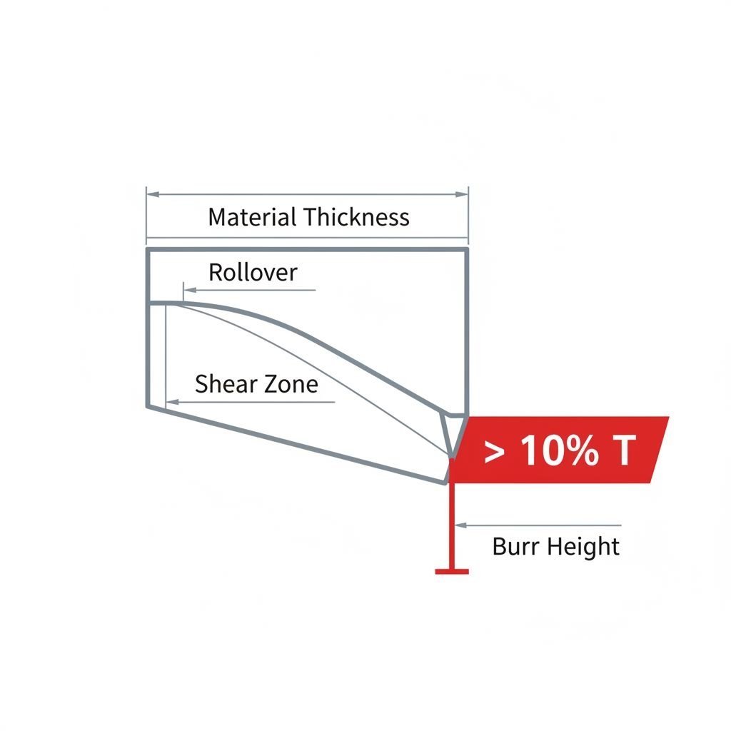
Burr Height Analysis
A sharp die produces a clean fracture with minimal burr. As the cutting edge rounds due to abrasive wear, the punch "pushes" the material rather than shearing it cleanly. Industry standards typically flag die maintenance when burr height exceeds 10% of material thickness or an absolute value of 0.05mm–0.1mm, depending on precision requirements.
Diagnosis Protocol:
- Use a micrometer or optical comparator to measure burr height at the same location on consecutive parts.
- Distinguish between rollover (the smooth curve on the die entry side) and burr (the sharp projection on the break side). Increased rollover indicates punch wear; increased burr indicates die button wear.
Surface Finish Degradation
Changes in the part's surface finish usually point to galling. If a normally smooth draw wall suddenly shows deep vertical scratches or "score lines," material is likely adhering to the die cavity. This is common in stainless steel and aluminum stamping where the material has a high affinity for tool steel.
Dimensional Drift
If hole sizes begin to shrink or slot positions drift, it often indicates significant edge wear or chipping. When a punch face chips, it creates an unbalanced load, causing the punch to deflect slightly, which moves the hole location and alters the clearance geometry.

Diagnostic Signal 2: Inspecting the Die Components
When the part indicates trouble, the next step is a physical inspection of the tool. This requires opening the press and cleaning the die surfaces to reveal subtle signs of degradation.
Heat Checking (Thermal Fatigue)
Heat checking appears as a network of fine, crazy-paving cracks on the die surface. It is caused by rapid thermal cycling—heating up during the work stroke and cooling down rapidly between hits. This is prevalent in high-speed operations or hot stamping.
- Risk: These micro-cracks can propagate deep into the tool steel, leading to catastrophic shattering.
- Detection: Use a dye penetrant or simply wipe the surface with a solvent; the solvent will evaporate from the surface but remain in the cracks, making them visible.
Galling Buildup (Pickup)
Inspect high-friction zones like draw beads and radii. Galling appears as silvery smears or deposits of the work material welded onto the tool steel. Even a deposit as thin as 10 microns can alter the friction coefficient enough to cause part splitting. Operators often use copper gauze to rub these areas; the soft copper will snag on microscopic galling peaks that are invisible to the naked eye.
Edge Chipping vs. Rounding
Distinguish between chipping (chunks missing) and rounding (smooth wear). Chipping suggests the tool material is too brittle or the press alignment is off (causing punch-die interference). Rounding is a natural result of abrasive wear and simply indicates the tool needs sharpening.
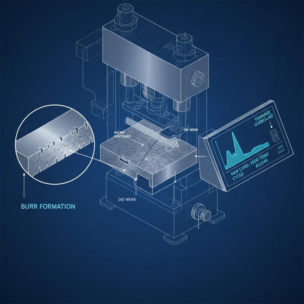
Diagnostic Signal 3: Process & Auditory Indicators
The press itself provides real-time feedback on die condition. Experienced operators often "hear" a problem before they see it.
Tonnage Monitor Spikes
As cutting edges dull, the force required to fracture the metal increases significantly. A tonnage monitor showing a gradual upward trend (e.g., +5% over a shift) indicates normal abrasive wear. A sudden spike, however, often signals a chipped punch or severe galling seizure.
Auditory Cues
A sharp die makes a crisp "snap" sound as it shears the metal. As the die wears, this sound changes to a dull, heavy "thud" or "bang." This change occurs because the dull edges are compressing the metal rather than cutting it cleanly, releasing energy later in the stroke (reverse tonnage).
Lubrication Analysis
Check the used lubricant or the bottom of the die shoe. If the oil is discolored or contains visible metal flakes (glitter), it indicates severe adhesive wear is generating debris. This "liquid sandpaper" will rapidly accelerate tool failure if not flushed.
Corrective Action: From Diagnosis to Solution
Once the wear type and location are identified, engineering must select the appropriate remedy. The solution depends on whether the goal is a quick fix or long-term process improvement.
| Symptom | Probable Cause | Immediate Fix | Long-Term Solution |
|---|---|---|---|
| Burrs > 0.1mm | Abrasive Wear (Dull Edges) | Sharpen/Grind Tooling | Upgrade to PM Steel (e.g., CPM 10V) |
| Score Marks on Part | Adhesive Wear (Galling) | Polish Die Surface | Apply TiAlN or DLC Coating |
| Chipped Punch | Brittleness/Misalignment | Replace Punch | Check Alignment; Use tougher steel (S7 vs D2) |
Strategic Upgrades: For persistent abrasive wear, upgrading from standard D2 tool steel to Powder Metallurgy (PM) steels can increase service life by 500% due to finer carbide distribution. For adhesive wear, physical vapor deposition (PVD) coatings like Titanium Carbo-Nitride (TiCN) provide a hard, slick barrier that prevents micro-welding.
For high-volume automotive programs where die longevity and precision are non-negotiable, partnering with specialized manufacturers is often the most effective preventive strategy. Companies like Shaoyi Metal Technology leverage IATF 16949-certified protocols and press capabilities up to 600 tons to bridge the gap from prototyping to mass production, ensuring tooling is engineered to withstand millions of cycles without premature degradation.
Mastering Die Maintenance
Effective die maintenance is not about reacting to broken tools; it is about predicting failure before it impacts part quality. By triangulating data from the stamped part (burrs/finish), the die surface (heat checking/pickup), and the press (tonnage/sound), manufacturers can shift from firefighting to planned maintenance. This proactive approach minimizes downtime, extends tool life, and ensures consistent quality in every stroke.
Frequently Asked Questions
1. What is the typical tolerance for stamped holes before maintenance is required?
While specific tolerances depend on the application, most precision stamping operations hold hole tolerances within +/- 0.002 inches (+/- 0.05mm). If measurements drift beyond this range or if hole geometry becomes oval, it indicates significant punch wear or deflection, requiring immediate sharpening or replacement.
2. What are the 7 steps in the stamping method?
The seven common metal stamping processes include Blanking (cutting the rough shape), Piercing (punching holes), Drawing (forming cup shapes), Bending (shaping angles), Air Bending (pressing into a die without bottoming out), Bottoming/Coining (stamping for high precision/imprint), and Trimming (removing excess material). Wear patterns manifest differently in each step, with drawing causing more galling and blanking causing more abrasive edge wear.
3. What is the difference between die cutting and stamping?
Die cutting typically refers to cutting softer materials (paper, fabric, rubber) or thin foils using a steel rule die or rotary die, often on a flatbed press. Stamping is a high-tonnage cold-forming process for metal, utilizing matched steel dies (punch and matrix) to shear, bend, or draw sheet metal into complex 3D shapes. Die wear in stamping is significantly more aggressive due to the high shear strength of metals.