 Produksi dalam jumlah kecil, standar tinggi. Layanan prototipisasi cepat kami membuat validasi lebih cepat dan mudah —

Bagian-Bagian Mesin Press Stamping: Komponen yang Paling Sering Rusak dan Mengapa Hal Ini Penting
Apa yang Membuat Press Stamping Bekerja
Pernahkah Anda bertanya-tanya apa yang mengubah lembaran baja datar menjadi panel pintu mobil Anda yang rumit atau braket presisi di dalam smartphone Anda? Jawabannya terletak pada salah satu mesin paling penting dalam manufaktur. Memahami apa itu press stamping dimulai dengan mengenali tujuan mendasarnya: mengubah bahan baku menjadi komponen jadi melalui gaya yang dikendalikan secara cermat.
Press stamping adalah alat mesin untuk pengerjaan logam yang membentuk atau memotong logam dengan mendistorsinya menggunakan die, serta memanfaatkan die jantan dan betina yang dibuat secara presisi untuk mengubah lembaran logam datar menjadi komponen berbentuk melalui penerapan gaya yang terkendali.
Bayangkanlah sebagai palu dan landasan zaman modern, tetapi dengan presisi dan tenaga luar biasa. Mesin press stamping logam mampu menghasilkan gaya mulai dari beberapa ton hingga ribuan ton, semuanya diarahkan dengan ketepatan presisi tinggi untuk menghasilkan komponen yang memenuhi spesifikasi tepat setiap kali.
Dari Lembaran Logam hingga Komponen Jadi
Lalu, sebenarnya apa yang dilakukan teknologi press logam selama proses stamping? Teknologi ini mengubah gerak rotasi menjadi gerak linear, kemudian menyalurkan energi tersebut ke dalam operasi pembentukan atau pemotongan. Lembaran logam atau gulungan logam mentah dimasukkan ke dalam press, di mana peralatan khusus yang disebut die membentuk material tersebut menjadi berbagai macam komponen—mulai dari braket sederhana hingga panel bodi otomotif yang kompleks.
Mesin stamping mencapai hal ini melalui tiga tahap terkoordinasi: memasukkan bahan ke posisi yang tepat, menerapkan gaya untuk membentuk atau memotong logam, serta mengeluarkan komponen jadi. Setiap siklus dapat berlangsung dalam pecahan detik, sehingga memungkinkan produksi dalam volume tinggi yang tidak dapat dicapai oleh metode manual.
Mengapa Pengetahuan tentang Anatomi Press Penting bagi Kualitas Produksi
Di sinilah aspek praktisnya muncul. Baik Anda seorang operator yang menjalankan peralatan setiap hari, teknisi pemeliharaan yang memastikan kelancaran operasionalnya, maupun insinyur manufaktur yang mengoptimalkan proses produksi, pemahaman terhadap anatomi press secara langsung memengaruhi keberhasilan Anda.
Pertimbangkan hal ini: ketika mesin stamping logam mulai menghasilkan komponen di luar spesifikasi, mengetahui sistem komponen mana yang perlu diperiksa dapat menghemat berjam-jam waktu pemecahan masalah. Saat merencanakan pemeliharaan preventif, pemahaman tentang cara kerja interaksi antarkomponen membantu Anda memprioritaskan pemeriksaan sebelum terjadinya kegagalan.
Artikel ini menggunakan pendekatan berbasis sistem untuk mengeksplorasi komponen press stamping. Alih-alih hanya mencantumkan bagian-bagiannya, kami akan mengelompokkannya berdasarkan sistem fungsional:
- Transmisi Daya – alur energi dari motor ke benda kerja
- Kontrol gerak – komponen yang membimbing dan mengatur pergerakan ram
- Pemasangan benda kerja – elemen yang mengamankan die dan bahan
- Sistem Keamanan – mekanisme pelindung yang menjaga keselamatan operator
Struktur ini membantu Anda memahami cara kerja komponen-komponen tersebut secara bersama-sama sebagai sistem terintegrasi, sehingga lebih mudah dalam mendiagnosis masalah serta mengambil keputusan yang tepat terkait perawatan, peningkatan, atau pembelian peralatan baru.
Dasar-Dasar Rangka dan Perakitan Bed
Bayangkan membangun sebuah rumah tanpa fondasi yang kokoh. Tak peduli seindah apa pun interior-nya atau secanggih apa pun peralatannya, pada akhirnya semuanya akan gagal. Prinsip yang sama berlaku pada press stamping. Rangka dan perakitan bed berfungsi sebagai tulang punggung struktural setiap press mekanis, menyerap gaya-gaya besar sekaligus mempertahankan keselarasan presisi yang dibutuhkan untuk produksi berkualitas.
Ketika sebuah mesin press capai logam menghasilkan ratusan ton gaya, sehingga energi tersebut memerlukan tempat untuk dialirkan. Rangka menahan dan mengarahkan gaya-gaya ini, mencegah lendutan yang dapat mengurangi ketepatan dimensi komponen. Memahami konstruksi rangka membantu Anda memprediksi kinerja peralatan dalam kondisi produksi serta alasan mengapa konfigurasi tertentu cocok untuk aplikasi spesifik.
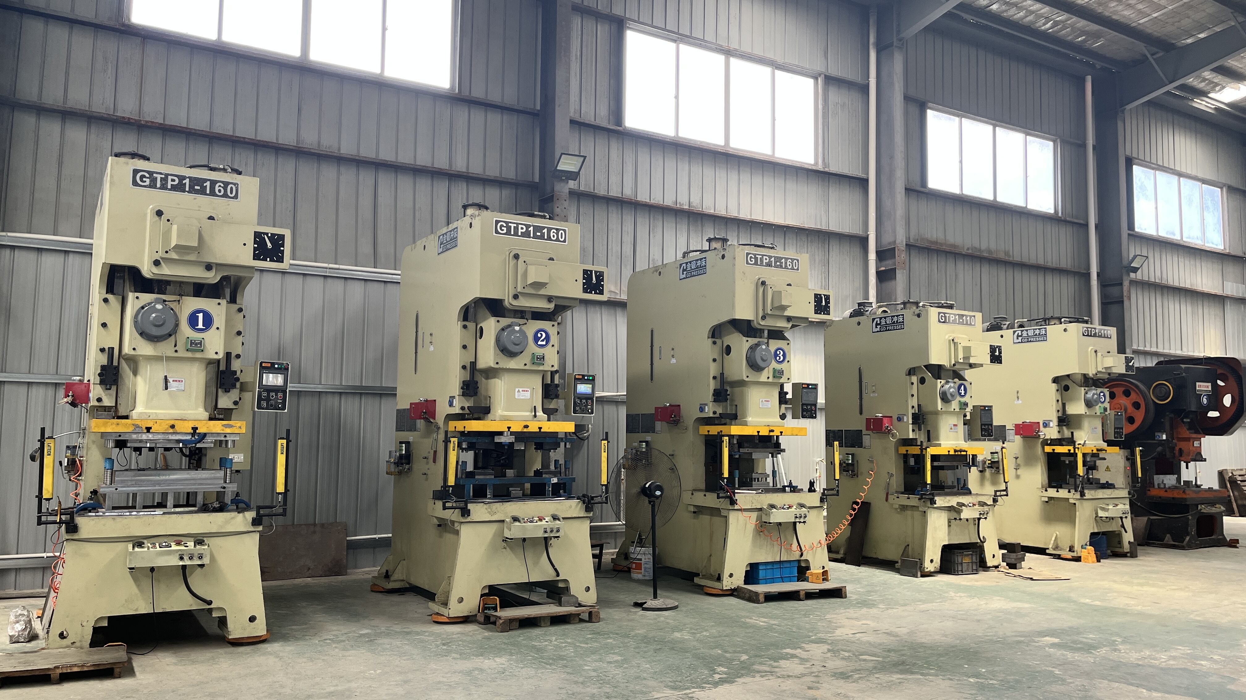
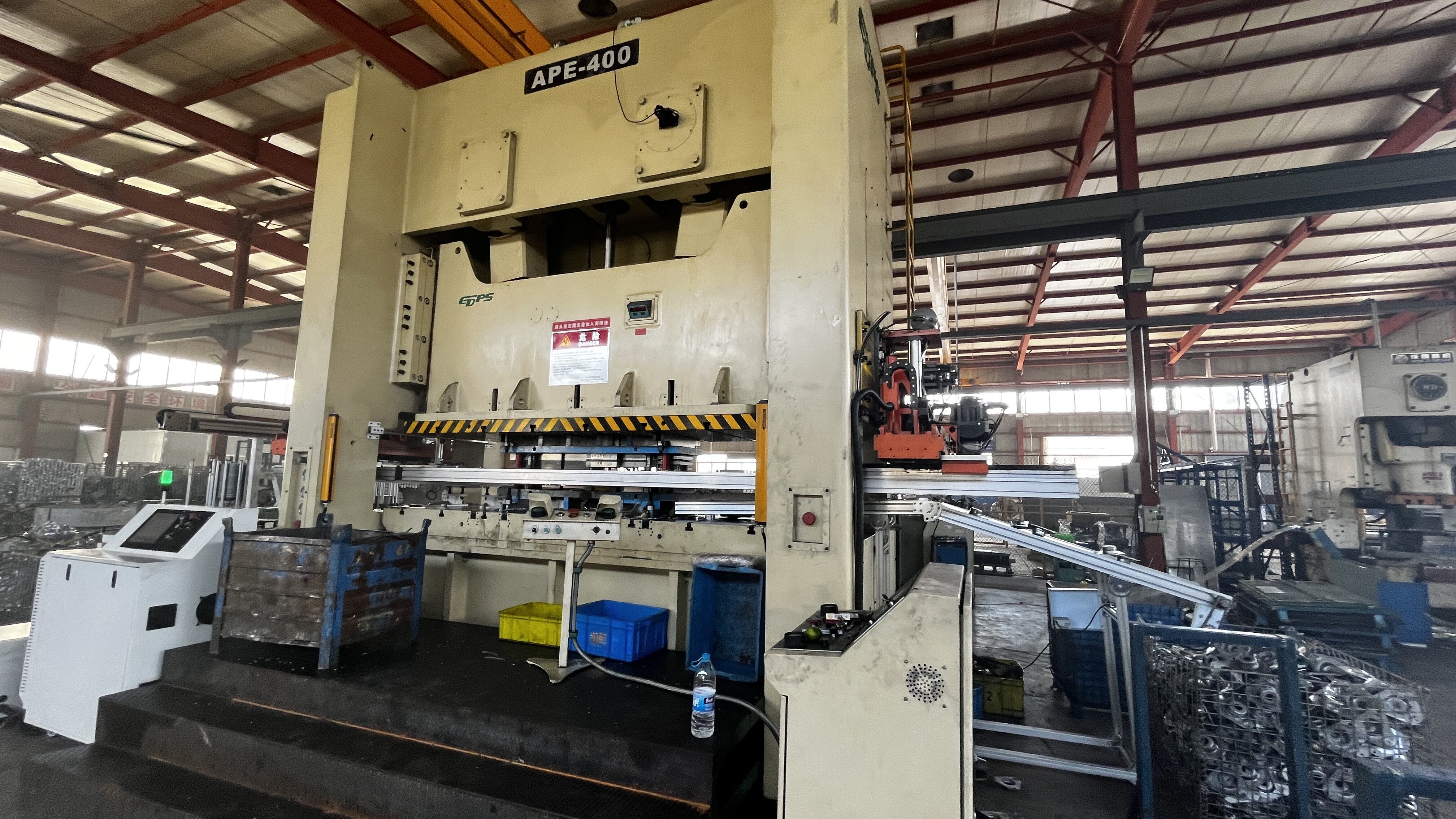
Desain Tekan C-Frame dibandingkan Desain Tekan Straight Side
Anda akan menemui tiga konfigurasi rangka utama pada mesin stamping logam, masing-masing menawarkan keunggulan tersendiri berdasarkan kebutuhan produksi Anda.
Press C-Frame (Gap Frame) fitur yang memiliki profil berbentuk-C khas, memberikan akses terbuka di tiga sisi. Desain ini membuat proses memuat dan membongkar benda kerja menjadi sangat efisien—bayangkan Anda dapat menggeser lembaran besar langsung ke posisinya tanpa harus menghindari rintangan. Jejak ukuran yang kompak juga menjadikan rangka-C ideal ketika ruang lantai terbatas. Namun, desain terbuka di bagian belakang memiliki konsekuensi: di bawah beban berat, rangka dapat mengalami lendutan sudut, yang memengaruhi presisi dalam aplikasi yang menuntut tinggi.
Rangka Sisi Lurus mengadopsi pendekatan yang sama sekali berbeda. Rangka ini juga dikenal sebagai rangka-H, yaitu mesin stamping yang dilengkapi dua tiang vertikal yang dihubungkan oleh bagian atap (crown) di atas dan landasan (bed) di bawah, sehingga membentuk struktur persegi panjang yang kaku. Hasilnya? Kekakuan yang unggul sehingga lendutan diminimalkan selama operasi berbeban tinggi. Ketika Anda melakukan proses deep drawing pada panel otomotif atau operasi blanking berat, stabilitas ini secara langsung berkontribusi pada konsistensi kualitas komponen.
Pilihan antara konfigurasi-konfigurasi ini sering kali bergantung pada pertanyaan mendasar: apakah Anda mengutamakan aksesibilitas dan fleksibilitas, atau kekakuan maksimum serta kapasitas gaya maksimum? Banyak fasilitas mengoperasikan kedua jenis tersebut, menyesuaikan karakteristik mekanisme press dengan kebutuhan pekerjaan tertentu.
Fungsi Ranjang dan Pelat Penopang
Rangkaian ranjang (bed) menahan die bawah dan menyerap dampak setiap langkah press. Bayangkanlah sebagai landasan dalam analogi palu-dan-landasan modern kita. Pelat penopang (bolster plate) dipasang langsung pada ranjang, menyediakan permukaan presisi yang telah dikerjakan dengan alur-T atau lubang ulir untuk memasang dan mengunci rangkaian die.
Setiap press stamping mencakup komponen struktural utama berikut yang bekerja secara bersamaan:
- Mahkota – Bagian atas yang menampung mekanisme penggerak dan mengarahkan gerak ram
- Tiang Tegak – Kolom vertikal yang menghubungkan crown ke ranjang, menahan gaya lentur
- Tempat Tidur – Bagian horizontal bawah yang menyerap gaya pembentukan
- Bolster Plate – Permukaan presisi yang dapat dilepas untuk pemasangan dan penyetelan die
- Batang ikat – Batang pengencang (pada desain sisi lurus) yang memberikan tegangan awal pada rangka untuk meningkatkan kekakuan
Pemilihan material untuk komponen-komponen ini melibatkan pertimbangan cermat terhadap berbagai kompromi. Rangka besi cor menawarkan peredaman getaran yang unggul—secara efektif menyerap kejut akibat operasi stamping, sehingga memperpanjang masa pakai die dan mengurangi kebisingan di tempat kerja. Sebaliknya, rangka baja yang dibuat melalui fabrikasi memberikan kekakuan dan kekuatan tarik yang lebih tinggi. Untuk dimensi yang sama, baja mengalami lendutan lebih kecil di bawah beban, menjadikannya pilihan utama untuk proses pembentukan presisi tinggi bahan berkekuatan tinggi maju.
Kapan masing-masing material unggul? Besi cor sangat cocok untuk stamping serba guna di mana pengendalian getaran menjadi faktor penting. Konstruksi baja menjadi mutlak diperlukan untuk press berukuran sangat besar atau aplikasi yang menuntut lendutan seminimal mungkin. Rangka baja yang direkayasa dengan baik dan telah mengalami proses peredaan tegangan mampu memberikan kekakuan ekstrem yang dibutuhkan ketika toleransi diukur dalam perseribu inci.
Spesifikasi rangka secara langsung menentukan aplikasi apa saja yang dapat ditangani oleh mesin press. Kapasitas tonase menetapkan gaya maksimum yang tersedia. Ukuran meja membatasi dimensi die Anda. Bukaan daylight—jarak maksimum antara meja dan ram pada posisi paling atas langkah—menentukan ketinggian maksimum komponen yang dapat Anda hasilkan. Memahami hubungan-hubungan ini membantu Anda mencocokkan kapabilitas mesin press dengan kebutuhan produksi, sehingga menghindari kesalahan mahal berupa spesifikasi peralatan yang terlalu rendah atau pengeluaran berlebihan untuk kapasitas yang tidak diperlukan.
Dengan fondasi struktural ini telah ditetapkan, pertanyaan selanjutnya menjadi: bagaimana energi sebenarnya mengalir melalui mesin press untuk menghasilkan gaya pembentukan? Hal ini membawa kita ke sistem transmisi daya.
Komponen Transmisi Daya dan Aliran Energi
Bayangkan ini: sebuah motor listrik berputar pada kecepatan konstan mampu menghasilkan ratusan ton gaya dalam sebagian kecil detik. Bagaimana transformasi tersebut terjadi? Jawabannya terletak pada sistem transmisi daya—jantung mekanis setiap press roda gila yang mengubah gerak rotasi kontinu menjadi tenaga pembentukan ledakan.
Memahami aliran energi ini mengungkap mengapa press mekanis mendominasi lingkungan produksi berkecepatan tinggi . Hal ini juga menjelaskan komponen mana yang paling dulu aus serta cara mendeteksi masalah sebelum mengakibatkan peralatan Anda tidak beroperasi.
Cara Roda Gila Menyimpan dan Melepaskan Energi
Roda gila pada dasarnya merupakan baterai energi berukuran besar. Selagi motor beroperasi terus-menerus pada daya relatif rendah, roda gila mengakumulasi energi kinetik rotasi selama beberapa putaran. Saat proses pembentukan terjadi, energi tersimpan ini dilepaskan dalam hitungan milidetik—menghasilkan daya sesaat jauh lebih besar daripada yang mampu dihasilkan motor secara tunggal.
Berikut adalah siklus kerja pada mesin press mekanis:
- Akumulasi energi – Motor menggerakkan roda gila melalui sabuk atau roda gigi, membangun momentum rotasi antar langkah penekanan
- Penghubungan kopling – Ketika operator memulai langkah penekanan, kopling menghubungkan roda gila yang berputar ke poros engkol
- Perpindahan Energi – Gerak rotasi roda gila diubah menjadi gerak linear landasan (ram) melalui mekanisme batang penghubung
- Aplikasi Gaya – Landasan (ram) bergerak turun, menerapkan gaya pembentukan pada benda kerja di dalam cetakan
- Fase Pemulihan – Setelah langkah penekanan selesai, motor mengisi kembali energi roda gila sebelum siklus berikutnya
Desain press mekanis ini memungkinkan hal luar biasa: motor berkekuatan 50 tenaga kuda dapat memberikan daya setara dengan 500 tenaga kuda atau lebih selama momen pembentukan sesungguhnya. Massa dan kecepatan rotasi roda gila menentukan jumlah energi yang tersedia. Roda gila yang lebih besar dan berputar lebih cepat menyimpan energi lebih banyak, sehingga memungkinkan operasi dengan kapasitas tonase lebih tinggi.
Terkesan rumit? Bayangkan seperti memutar pegas. Anda menerapkan gaya secara bertahap dalam kurun waktu tertentu, lalu melepaskannya sekaligus. Roda gila melakukan hal yang sama terhadap energi rotasi, sehingga memungkinkan pembentukan logam dengan presisi tinggi pada mesin press berkecepatan tinggi tanpa memerlukan motor berdaya sangat besar dan boros energi.
Penjelasan Sistem Kopling dan Rem
Jika roda gila berfungsi seperti baterai, maka kopling dan rem berperan sebagai saklar yang mengatur kapan energi mengalir dan kapan gerak berhenti. Komponen-komponen ini bekerja secara berlawanan—ketika satu aktif, yang lainnya melepas—menghasilkan pengendalian presisi yang dibutuhkan untuk operasi mekanis press yang aman.
Mekanisme Kopling terdiri dari tiga jenis utama, masing-masing cocok untuk aplikasi berbeda:
- Kopling gesek – Menggunakan tekanan pneumatik untuk menekan cakram gesek ke permukaan roda gila, ideal untuk aplikasi kecepatan variabel dan langkah parsial
- Kopling positif – Menggunakan rahang atau pin mekanis yang mengunci ke dalam bukaan roda gila, memberikan keterkaitan langsung (positif) untuk operasi berbeban tinggi
- Kopling pneumatik – Jenis yang paling umum digunakan pada pres mekanis modern, menawarkan keterkaitan yang halus dan penyesuaian yang mudah
Sistem rem mencerminkan desain kopling, menggunakan mekanisme gesekan serupa untuk menghentikan ram ketika kopling melepaskan kaitan. Pada sebagian besar pres, perangkat kopling dan rem dipasang pada poros yang sama, berbagi komponen sambil menjalankan fungsi yang berlawanan.
Berikut alasan mengapa perawatan sangat krusial: lapisan kopling dan rem merupakan komponen habis pakai yang dirancang untuk aus. Mengenali indikator keausan mencegah kegagalan berbahaya serta waktu henti tak terjadwal yang mahal.
Tanda peringatan yang memerlukan perhatian segera:
- Jarak pengereman atau waktu pengereman yang meningkat
- Ram melewati posisi yang diharapkan (overrun)
- Selip selama proses pembentukan (penurunan kapasitas tonase)
- Suara tidak biasa saat keterkaitan atau pengereman
- Keausan terlihat jelas pada permukaan gesek melebihi spesifikasi ketebalan minimum
- Konsumsi udara berlebih pada sistem pneumatik
Sebagian besar produsen menetapkan ketebalan minimum kampas—biasanya ketebalan 50% dari ketebalan asli menandakan waktu penggantian. Waktu pengereman harus tetap berada dalam batas yang diwajibkan oleh OSHA, umumnya diukur dalam milidetik berdasarkan kecepatan press dan posisi langkah.
Pemilihan antara transmisi daya mekanis dan hidrolik sangat bergantung pada kebutuhan produksi Anda. Masing-masing teknologi menawarkan keunggulan tersendiri:
| Karakteristik | Pem press mekanis | Mesin pencetak hidraulik |
|---|---|---|
| Rentang kecepatan | 10–1800 siklus per menit | 10–50 siklus per menit (khas) |
| Konsistensi Gaya | Gaya maksimum hanya tersedia di dekat akhir langkah | Gaya penuh tersedia sepanjang seluruh langkah |
| Efisiensi Energi | Efisiensi lebih tinggi dalam siklus kecepatan tinggi | Energi dikonsumsi hanya selama bagian kerja |
| Kontrol Gaya | Kurva gaya tetap berdasarkan desain mekanis | Gaya dan kecepatan dapat disesuaikan pada posisi langkah mana pun |
| Aplikasi Terbaik | Blanking, stamping, dan pekerjaan die progresif dalam volume tinggi | Deep drawing, forming, serta aplikasi yang memerlukan waktu tahan (dwell time) |
| Fokus Perawatan | Keausan kopling/rem dan sistem pelumasan | Kondisi fluida hidrolik serta integritas seal |
Untuk aplikasi press stamping berkecepatan tinggi yang memproduksi ribuan komponen per jam, press mekanis dengan penyimpanan energi roda gila tetap menjadi standar industri. Kemampuannya beroperasi secara cepat sambil memberikan gaya forming yang konsisten menjadikannya ideal untuk operasi die progresif dan jalur press transfer.
Sekarang setelah Anda memahami aliran energi melalui press, pertanyaan logis berikutnya adalah: bagaimana energi tersebut diarahkan secara presisi? Jawabannya terletak pada rakitan ram dan slide—komponen bergerak yang pada akhirnya memberikan gaya forming ke benda kerja Anda.
Mekanika Rakitan Ram dan Slide
Ram adalah komponen tempat energi yang tersimpan diubah menjadi kerja produktif. Setiap mesin press stamping mengandalkan komponen bergerak ini untuk memberikan gaya pembentukan yang dikontrol secara presisi ke die di bawahnya. Memahami anatomi ram—dan cara sistem pendukungnya mempertahankan akurasi—membantu Anda mengenali pola keausan sebelum hal tersebut mengurangi kualitas komponen atau efisiensi produksi.
Bayangkan ram sebagai kepalan tangan terkendali dari press. Komponen ini bergerak naik-turun ribuan kali per shift, dipandu oleh permukaan presisi sambil membawa perlengkapan die atas yang dapat memiliki berat ratusan bahkan ribuan pound. Menjaga komponen masif ini bergerak dengan lancar memerlukan sistem terintegrasi yang terdiri atas mekanisme panduan, penyeimbang beban (counterbalancing), dan penyetelan.
Kontrol Gerak Ram dan Presisi
Ram (juga disebut slide dalam terminologi industri) terhubung ke sistem transmisi daya melalui mekanisme penghubung—biasanya batang penghubung yang terpasang pada eksentrik atau poros engkol. Saat poros engkol berputar, hubungan ini mengubah gerak rotasi menjadi gerak bolak-balik vertikal yang digunakan untuk menjalankan operasi penekanan logam.
Setiap perakitan ram mencakup komponen-komponen esensial berikut yang bekerja secara bersamaan:
- Geser – Badan bergerak utama yang menopang die atas dan menyalurkan gaya pembentukan
- Motor Penyesuaian Geser – Menggerakkan mekanisme yang mengubah tinggi tutup (shut height) untuk berbagai konfigurasi die
- Gibbs – Elemen pemandu yang dapat disetel guna menjaga keselarasan slide di dalam rangka
- Silinder penyeimbang – Silinder pneumatik yang mengimbangi berat slide dan peralatan cetak (tooling)
- Mekanisme penghubung – Lengan pitman atau batang penghubung yang menghubungkan slide ke poros engkol
Dua spesifikasi secara mendasar menentukan apa yang dapat dihasilkan oleh sebuah press: panjang langkah dan jumlah langkah per menit. Panjang langkah menentukan tinggi maksimum komponen yang dapat Anda bentuk—langkah yang lebih panjang memungkinkan pembentukan komponen yang lebih tinggi serta operasi pembentukan yang lebih kompleks. Jumlah langkah per menit (SPM) menetapkan kecepatan produksi, dengan press logam berkisar dari 10 SPM untuk pekerjaan pembentukan berat hingga lebih dari 1.000 SPM untuk operasi die progresif berkecepatan tinggi.
Berikut adalah komprominya: kecepatan yang lebih tinggi menghasilkan lebih banyak komponen per jam, tetapi membatasi kompleksitas operasi yang dapat Anda lakukan. Operasi deep drawing dan pembentukan berat memerlukan kecepatan yang lebih rendah agar material dapat mengalir secara memadai. Sementara itu, operasi blanking dan pembentukan dangkal dapat mentolerir kecepatan yang jauh lebih tinggi.
Penyesuaian Slide untuk Pengaturan Tinggi Die
Die yang berbeda memiliki tinggi tutup (shut height) yang berbeda—yaitu jarak dari pelat penopang (bolster plate) ke bagian bawah ram saat berada dalam posisi tertutup penuh. Mekanisme penyesuaian landasan geser (slide adjustment) memungkinkan operator mengangkat atau menurunkan posisi bawah ram, sehingga dapat menampung berbagai jenis peralatan tanpa memerlukan modifikasi mekanis.
Di sinilah sistem penyeimbang (counterbalance) menjadi sangat krusial. Menurut Dokumentasi teknis AIDA , penyetelan sistem penyeimbang yang tepat mengangkat beban landasan geser (slide) dan peralatan dari sekrup penyetel tinggi tutup (shut height adjusting screws) selama proses pemasangan, sehingga memudahkan motor penyetel memutar sekrup tersebut tanpa kelebihan beban atau terhenti (stalling). Sistem penyeimbang menggunakan silinder pneumatik—biasanya dua atau empat unit, tergantung pada ukuran press—untuk menghasilkan gaya ke atas yang menetralisir beban menggantung dari landasan geser dan peralatan.
Apa yang terjadi ketika tekanan penyeimbang tidak tepat? Sistem yang tidak disetel dengan benar memungkinkan permukaan ulir pada sekrup pengatur menekan keluar pelumas, sehingga meningkatkan gesekan dan keausan. Seiring waktu, hal ini menyebabkan kegagalan dini pada mekanisme pengatur yang mahal dan bahkan dapat menyebabkan peluncur (slide) merayap ke bawah saat mesin press tidak beroperasi.
Sistem gib menjaga keselarasan peluncur (slide) selama setiap langkah. Mesin stamping menggunakan dua desain gib utama:
- Gib busing perunggu – Desain tradisional yang menggunakan permukaan aus perunggu yang diresapi minyak, yang meluncur terhadap rel baja keras. Komponen ini memerlukan pelumasan dan penyetelan berkala seiring terjadinya keausan.
- Gib bantalan rol – Desain premium modern yang menggunakan elemen rol presisi guna menghilangkan hampir seluruh gesekan geser. Desain ini menawarkan masa pakai lebih panjang serta mempertahankan toleransi yang lebih ketat, meskipun biaya awalnya lebih tinggi.
Celah gib secara langsung memengaruhi kualitas komponen dalam cara yang dapat diukur. Ketika celah melebihi spesifikasi—biasanya lebih dari 0,001 hingga 0,002 inci, tergantung pada kelas press—peluncur (slide) dapat bergeser secara lateral selama proses pembentukan. Pergerakan ini menyebabkan aliran material yang tidak merata, variasi dimensi, serta keausan cetakan yang lebih cepat. Pada aplikasi stamping presisi, keausan gib yang berlebihan tampak sebagai variasi antarkomponen sebelum operator bahkan menyadari gejala mekanisnya.
Bagaimana Anda mengetahui kapan penyetelan atau penggantian gib diperlukan? Perhatikan indikator-indikator berikut:
- Cahaya tampak (daylight) yang terlihat di antara permukaan gib dan peluncur (slide)
- Suara ketukan yang terdengar saat arah gerak peluncur (stroke) dibalik
- Peningkatan variasi dimensi pada komponen hasil stamping
- Pola keausan yang tidak merata pada tepi pemotong cetakan
- Konsumsi pelumas yang lebih tinggi dari biasanya
Penyesuaian gib secara berkala menjaga presisi yang dituntut oleh produksi berkualitas tinggi. Sebagian besar produsen menetapkan interval pemeriksaan berdasarkan jam produksi, dengan penyesuaian diperlukan setiap kali celah melebihi batas yang dipublikasikan. Pemeliharaan proaktif di sini mencegah kegagalan berantai yang terjadi ketika ketidaksejajaran memberi tekanan berlebih pada komponen press lainnya.
Dengan ram yang memberikan gerak terkendali, pertimbangan berikutnya adalah bagaimana peralatan (tooling) terintegrasi dengan komponen press. Set die membentuk antarmuka antara bahan baku dan komponen jadi—serta hubungannya dengan spesifikasi press menentukan baik kualitas produk maupun masa pakai peralatan.
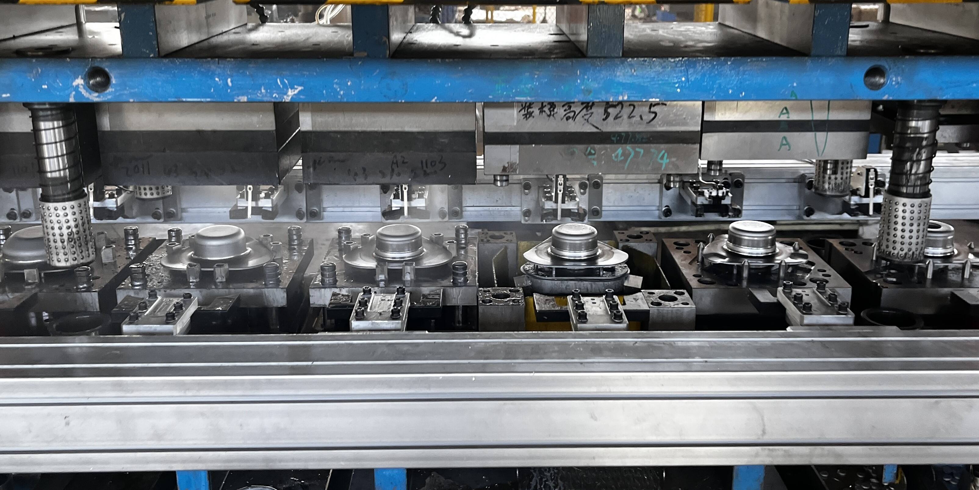
Integrasi Set Die dan Antarmuka Peralatan
Berikut adalah kenyataan yang sering diabaikan banyak produsen: bahkan press stamping paling canggih sekalipun menjadi tidak berguna tanpa peralatan cetak (tooling) yang sesuai secara tepat. Set die merupakan antarmuka kritis tempat kemampuan press bertemu dengan kebutuhan produksi. Memahami cara komponen die stamping terintegrasi dengan bagian-bagian press membantu Anda menghindari ketidaksesuaian mahal serta memaksimalkan umur pakai alat cetak (tool life) dan kualitas komponen.
Bayangkan set die sebagai end-effector khusus yang mengubah gaya tekan (press force) umum menjadi komponen berbentuk presisi. Setiap press stamping logam mengandalkan antarmuka peralatan cetak ini untuk mengubah tenaga mentah menjadi pekerjaan produktif. Ketika spesifikasi die selaras sempurna dengan kemampuan press, Anda mencapai kualitas konsisten pada efisiensi maksimum. Jika tidak? Siapkan diri menghadapi keausan dini, masalah dimensi, dan waktu henti (downtime) yang menjengkelkan.
Komponen Set Die yang Dipasang pada Press
Satu set die lengkap terdiri atas beberapa komponen yang bekerja secara bersamaan, masing-masing berfungsi khusus sekaligus berinteraksi dengan bagian press tertentu. Memahami hubungan-hubungan ini membantu Anda dalam mendiagnosis masalah serta menentukan peralatan cetak yang memaksimalkan kemampuan peralatan Anda.
The dudukan mati membentuk fondasi keseluruhan set die. Menurut dokumentasi industri mengenai struktur cetakan stamping, die shoe berfungsi sebagai struktur penopang bawah keseluruhan cetakan, memainkan peran kritis dalam menopang perakitan serta menyalurkan gaya operasi punch. Die shoe atas dan bawah dipasang masing-masing ke ram dan bolster plate, sehingga membentuk kerangka yang menjaga semua komponen die lainnya dalam posisi penyelarasan yang presisi.
The pegangan punch mengamankan pons dan alat pembentuk ke sepatu die atas. Komponen ini harus mampu menahan gaya bentur yang sangat besar sambil mempertahankan posisi tepat masing-masing pons. Desain yang dapat diganti memungkinkan penggantian pons tanpa harus mengganti seluruh perakitan atas—hal ini sangat penting untuk menjaga kelangsungan produksi ketika elemen pemotong individual mengalami keausan.
The pelat Penyepit melaksanakan beberapa fungsi kritis selama setiap langkah penekanan. Komponen ini menahan benda kerja rata di atas blok die selama proses pembentukan, mencegah material terangkat bersama pons pada gerak naik (upstroke), serta melindungi operator dengan mengendalikan pergerakan material. Stripper berpegas memberikan tekanan terkendali, sedangkan stripper padat memberikan kekakuan maksimum untuk operasi blanking presisi.
The die Block memuat rongga pemotongan dan pembentukan untuk wanita yang membentuk benda kerja. Komponen ini dipasang pada alas die bagian bawah dan berinteraksi langsung dengan pelat penopang melalui alas tersebut. Blok die mengalami benturan konstan dan harus mempertahankan ketajaman tepi pemotongnya selama jutaan siklus—sehingga pemilihan material dan perlakuan panas menjadi krusial bagi umur pakai alat.
Berikut cara komponen-komponen ini berinteraksi dengan bagian press:
| Komponen Set Die | Fungsi utama | Antarmuka Komponen Press |
|---|---|---|
| Alas Die Bagian Atas | Menopang semua komponen die bagian atas; menyalurkan gaya ram ke punch | Dipasang pada permukaan ram melalui alur-T atau pola baut |
| Alas Die Bawah | Menopang blok die dan komponen bagian bawah; menyerap gaya pembentukan | Dikencangkan ke pelat penopang melalui alur-T atau sistem penjepit |
| Pegangan punch | Menahan dan memposisikan punch pemotongan/pembentukan | Dipasang pada alas die atas; disejajarkan oleh pin penuntun |
| Pelat Penyepit | Menahan bahan dalam posisi datar; melepaskan benda kerja dari pukulan | Dipandu oleh pin yang dipasang pada alas die |
| Die Block | Berisi rongga pemotongan wanita (female) dan fitur pembentukan | Dibautkan pada alas die bawah; menerima dampak dari pukulan |
| Pins pandu | Menyejajarkan alas die atas dan bawah secara presisi | Ditekan ke dalam salah satu alas die; dipandu oleh bushing pada alas die berseberangan |
| Bushing Penuntun | Menyediakan permukaan geser presisi untuk pin penuntun | Ditekan ke dalam alas die yang berseberangan dengan pin penuntun |
Cara Sistem Panduan Memastikan Keselarasan
Pin panduan dan busing memerlukan perhatian khusus karena menentukan akurasi keselarasan sepanjang masa pakai cetakan. Sebagai Seri ilmu cetakan dari The Fabricator menjelaskan , fungsi pin panduan adalah untuk menempatkan sol sebelah atas dan bawah secara tepat sehingga semua komponen cetakan dapat saling berinteraksi secara presisi. Pin-pin tersebut mengarahkan komponen pemotong dan pembentuk agar jarak bebas yang benar dapat dicapai dan dipertahankan secara efektif.
Dua jenis pin panduan utama melayani kebutuhan produksi yang berbeda:
- Pin gesekan (bantalan biasa) – Berukuran sedikit lebih kecil daripada diameter dalam busing, bersentuhan langsung dengan permukaan busing. Busing aluminium-perunggu dengan sumbat grafit mengurangi gesekan. Paling cocok untuk aplikasi dengan dorongan samping signifikan, tetapi terbatas pada kecepatan rendah karena pembentukan panas.
- Pin Bantalan Bola – Beroperasi pada bantalan bola presisi yang terkandung dalam sangkar aluminium. Bantalan ini secara signifikan mengurangi gesekan, memungkinkan operasi kecepatan tinggi sambil mempertahankan toleransi yang lebih ketat. Perakitan pin dan bantalan sebenarnya berukuran sekitar 0,0002 inci lebih besar daripada diameter dalam bushing—menciptakan apa yang disebut produsen sebagai "slop negatif" untuk presisi maksimal.
Berikut adalah poin kritis yang sering diabaikan banyak orang: pin penuntun tidak mampu mengkompensasi press yang tidak terawat dengan baik. Seperti ditekankan para pakar industri, baik die maupun press berfungsi sebagai bagian dari suatu sistem terintegrasi. Pin penuntun berukuran terlalu besar atau jumlahnya berlebih tidak akan memperbaiki kekenduran ram atau keausan gibs press. Press harus dipandu secara independen dengan presisi agar sistem penuntun die dapat berfungsi sebagaimana mestinya.
Pegas die juga memainkan peran penting dalam sistem panduan. Pegas-pegas ini memberikan dukungan elastis dan gaya pemulih sekaligus menyerap kejut dan getaran selama setiap langkah kerja. Sistem berkode warna membantu pengguna memilih laju pegas yang sesuai untuk aplikasi tertentu, sehingga sesuai dengan kebutuhan gaya pelat penarik (strippers) dan bantalan tekan (pressure pads).
Menyesuaikan Spesifikasi Press dengan Kebutuhan Die
Penyesuaian yang tepat antara die dan press melibatkan tiga spesifikasi kritis yang harus selaras agar operasi berjalan sukses.
Kapasitas Tonnase menentukan apakah press mampu memberikan gaya yang cukup untuk operasi pembentukan Anda. Perkiraan kebutuhan tonase yang terlalu rendah menyebabkan press macet atau kelebihan beban, yang berpotensi merusak peralatan maupun perangkat cetak (tooling). Mesin stamping lembaran logam berkapasitas 200 ton tidak dapat dioperasikan secara aman dengan die yang memerlukan gaya sebesar 250 ton—terlepas dari seberapa singkatnya durasi puncak gaya tersebut.
Tinggi tutup (juga disebut tinggi die) merupakan jarak vertikal dari pelat bolster ke bagian bawah ram saat posisi sepenuhnya tertutup. Menurut panduan teknis mengenai pemilihan tinggi cetakan , tinggi gabungan cetakan atas dan bawah tidak boleh melebihi tinggi penutupan (shut height) press—jika tidak, cetakan tidak dapat dipasang atau dioperasikan secara aman. Sebagian besar aplikasi press stamping logam lembaran memerlukan margin 5–10 mm untuk mencegah tumbukan selama operasi.
Dimensi meja press harus mampu menampung jejak dasar cetakan (die shoe footprint) dengan ruang tambahan untuk pengikatan. Cetakan yang pas tepat pada meja press tanpa sisa ruang tidak memberikan margin untuk mengamankan peralatan secara memadai, sehingga berisiko bergerak selama operasi dan merusak baik cetakan maupun press.
Ketika spesifikasi-spesifikasi ini selaras secara tepat, Anda akan memperoleh:
- Dimensi komponen yang konsisten sepanjang proses produksi
- Masa pakai cetakan yang lebih panjang akibat distribusi gaya yang tepat
- Penurunan keausan press karena pengoperasian dalam batas desainnya
- Pemasangan peralatan yang lebih cepat karena cetakan pas tanpa memerlukan modifikasi
Kesesuaian yang buruk menghasilkan hasil sebaliknya—keausan yang dipercepat, variasi dimensi, dan siklus penyesuaian yang menjengkelkan yang tak pernah benar-benar menyelesaikan ketidaksesuaian mendasar tersebut. Mengalokasikan waktu di awal untuk memverifikasi spesifikasi secara menyeluruh akan mencegah masalah-masalah ini sepenuhnya.
Setelah integrasi die dipahami, pertimbangan berikutnya melibatkan peralatan tambahan yang memasok bahan ke dalam press dan mengeluarkan komponen jadi. Sistem-sistem ini harus disinkronkan secara presisi dengan waktu operasi press guna mencapai produksi berkecepatan tinggi yang menjadi alasan investasi pada press stamping.
Peralatan Tambahan dan Sistem Pemasok Bahan
Anda telah menguasai press itu sendiri—tetapi bagaimana dengan semua perangkat yang mengelilinginya? Sebuah press stamping yang menganggur di antara siklus pemuatan manual akan menyia-nyiakan sebagian besar potensi produktifnya. Peralatan tambahan yang memasok bahan, menjaga ketegangan, serta mengeluarkan komponen jadi mengubah press mandiri menjadi sistem produksi utuh yang mampu memproduksi ribuan komponen per jam.
Komponen pendukung ini sering kali mendapatkan perhatian lebih sedikit dibandingkan mesin press itu sendiri, namun justru komponen-komponen tersebut kerap menentukan laju produksi aktual. Ketika mesin stamping logam industri Anda mampu beroperasi hingga 600 siklus per menit, tetapi feeder Anda hanya mampu mencapai maksimal 400 siklus per menit, tebak komponen mana yang menjadi batasan utama dalam produksi? Memahami cara sistem tambahan terintegrasi dengan siklus waktu press mengungkap peluang untuk memanfaatkan kapasitas yang sudah Anda miliki.
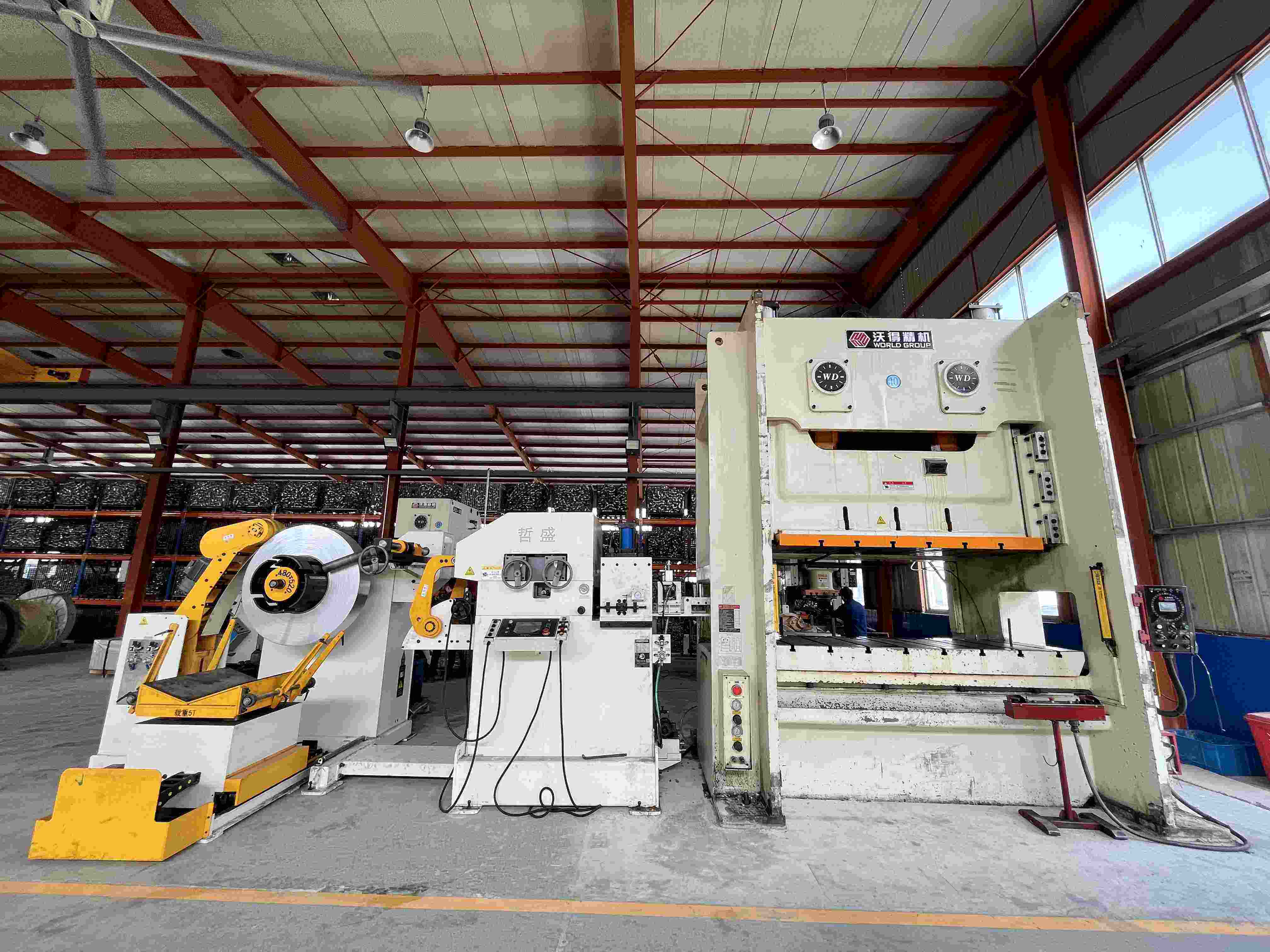
Sistem Pemberi Gulungan dan Penanganan Material
Operasi stamping modern jarang dimulai dari blank individual. Sebagai gantinya, material tiba dalam bentuk gulungan dengan berat hingga 23 ton atau lebih, sehingga memerlukan peralatan khusus untuk membuka gulungan, meratakan, serta memasukkan bahan ke dalam press dengan ketepatan waktu yang presisi. Menurut Dokumentasi teknis Power Line Schuler , jalur pemberi gulungan harus mampu mendukung proses produksi yang sangat dinamis sekaligus menangani lebar strip hingga 1.850 mm dan ketebalan material hingga 8 mm.
Setiap jalur pemberi gulungan mencakup kategori peralatan esensial berikut yang bekerja secara berurutan:
- Dudukan kumparan dan alat pembuka kumparan – Menopang dan memutar kumparan, serta mengeluarkan material dengan laju terkendali. Mandrel bermotor mengembang untuk mencengkeram diameter dalam kumparan, sedangkan penuntun sisi hidrolik memusatkan lembaran logam.
- Alat pelurus dan perata – Menghilangkan kelengkungan akibat penggulungan (coil set) serta meratakan material. Rol penarik mencengkeram lembaran logam, sementara rol pelurus presisi menerapkan lenturan terkendali guna menghilangkan sifat elastis material.
- Unit pengendali loop – Membentuk buffer material antara alat pelurus yang beroperasi secara kontinu dan alat pemberi material yang beroperasi secara start-stop. Sensor memantau kedalaman loop untuk memastikan ketersediaan material yang cukup pada setiap langkah penekanan.
- Servo feeders – Memajukan panjang material secara presisi ke dalam die pada interval waktu yang tepat, disinkronkan secara akurat dengan gerak press. Teknologi servo modern memungkinkan akurasi pemberian material hingga seperseribu inci.
- Pemotong limbah – Memotong limbah berbentuk rangka (skeleton waste) dan potongan tepi menjadi potongan-potongan yang mudah ditangani untuk didaur ulang. Diposisikan di outlet press guna menangani aliran limbah kontinu.
- Sistem pelontar komponen – Angkat komponen jadi dari area die menggunakan semburan udara, alat pengungkit mekanis, atau sistem konveyor yang mencegah kerusakan komponen dan memungkinkan operasi berkecepatan tinggi.
Mengapa unit loop begitu penting? Mesin pelurus beroperasi secara terus-menerus untuk menjaga konsistensi sifat material, sedangkan mesin pemberi bahan beroperasi dalam siklus mulai-berhenti yang disinkronkan dengan press. Lubang loop atau sistem loop datar mengatasi perbedaan waktu ini dengan menyimpan cukup material untuk memasok setiap langkah pemberian bahan tanpa mengganggu proses pelurusan.
Komponen Otomatisasi untuk Produksi Berkecepatan Tinggi
Otomatisasi press stamping telah berkembang pesat jauh melampaui penanganan material sederhana. Instalasi press stamping berkecepatan tinggi saat ini mengintegrasikan sistem penginderaan, penentuan posisi, dan pengendalian kualitas yang canggih, sehingga memungkinkan laju produksi yang tak terbayangkan oleh generasi sebelumnya.
Teknologi Pemberian Bahan Servo mewakili kemajuan yang mungkin paling signifikan. Berbeda dengan sistem pengumpan mekanis yang digerakkan oleh cam atau mekanisme penghubung, pengumpan servo menggunakan motor listrik yang dapat diprogram untuk mempercepat, mengatur posisi, dan memperlambat bahan dengan presisi yang ditentukan oleh perangkat lunak. Fleksibilitas ini memungkinkan mesin stamping baja yang sama menjalankan panjang pengumpan dan profil waktu yang berbeda tanpa pergantian komponen mekanis—cukup muat parameter baru dan jalankan.
Mekanisme pelepasan pilot berkoordinasi dengan pilot die untuk memastikan pendaftaran bahan yang presisi. Ketika die menutup, pilot memasuki lubang-lubang yang telah dilubangi sebelumnya guna menempatkan strip secara tepat. Sistem pengumpan harus melepaskan tekanan penjepitan pada saat yang tepat, sehingga pilot dapat melakukan koreksi posisi akhir sebelum proses pembentukan dimulai. Pelepasan yang tidak tepat waktunya menyebabkan kerusakan pada pilot dan kesalahan pendaftaran.
Sensor bahan memantau berbagai kondisi selama siklus pengumpanan:
- Detektor kesalahan pengumpanan memverifikasi bahwa bahan telah maju sejauh jarak yang benar sebelum setiap langkah.
- Sensor pengait mendeteksi kemacetan bahan antara feeder dan die
- Panduan tepi memverifikasi bahwa pelacakan strip tetap berada di tengah
- Sensor akhir kumparan memicu penghentian otomatis sebelum bahan habis
Menurut Panduan integrasi komprehensif dari JR Automation , otomatisasi yang efektif dalam proses stamping menciptakan proses yang sepenuhnya tersinkronisasi, di mana setiap gerakan harus diatur secara sempurna guna memaksimalkan laju produksi dan menjamin kualitas. Sinkronisasi ini meliputi penanganan komponen oleh robot, sistem inspeksi berbasis visi, serta perakitan rak otomatis—mengubah mesin stamping logam menjadi satu elemen dalam sel produksi terintegrasi.
Berikut adalah persyaratan sinkronisasi kritis: spesifikasi peralatan tambahan harus sesuai dengan laju langkah press dan kemampuan panjang umpan. Sebuah press yang beroperasi pada 300 SPM dengan kemajuan umpan 4 inci memerlukan alat umpan yang mampu menggerakkan material sepanjang 100 kaki per menit—dan berakselerasi hingga kecepatan penuh di antara setiap langkah. Loop harus mampu menyimpan cukup material untuk beberapa langkah, sedangkan pelurus (straightener) harus mampu memasok material lebih cepat daripada laju konsumsi oleh alat umpan.
Ketika terjadi ketidaksesuaian spesifikasi, komponen terlambat akan membatasi seluruh sistem. Menginvestasikan dana pada press berkecepatan tinggi sementara tetap menggunakan peralatan umpan berkapasitas rendah justru menciptakan bottleneck mahal. Sebaliknya, penggunaan peralatan tambahan berkapasitas berlebihan akan membuang modal yang sebenarnya dapat digunakan untuk meningkatkan area produksi lainnya. Penyesuaian sistem yang tepat—dengan mempertimbangkan semua komponen sebagai satu lini terintegrasi—memaksimalkan pengembalian investasi Anda dalam proses stamping.
Dengan material yang mengalir lancar dalam proses produksi, perhatian secara alami beralih ke sistem-sistem yang melindungi operator dan memastikan konsistensi kualitas. Teknologi keselamatan dan pengendali modern telah mengubah cara kerja mesin stamping—dan memahami sistem-sistem ini merupakan hal esensial bagi siapa pun yang bertanggung jawab atas operasi atau pemeliharaan mesin stamping.
Sistem Keselamatan dan Pengendali Modern
Apa yang terjadi ketika terjadi kegagalan pada kecepatan 600 kali tekanan per menit? Perbedaan antara insiden nyaris terjadi dan bencana sering kali ditentukan oleh sistem keselamatan dan pengendali yang bereaksi lebih cepat daripada kemampuan manusia mana pun. Memahami komponen-komponen ini bukan hanya soal kepatuhan terhadap regulasi—melainkan juga tentang melindungi manusia sekaligus mempertahankan efisiensi produksi yang menjadi dasar investasi peralatan Anda.
Mesin press stamping modern sangat berbeda dibandingkan pendahulunya yang bersifat mekanis, khususnya dalam hal arsitektur pengendaliannya. Jika dulu operator mengandalkan pelindung fisik dan kunci mekanis, kini sistem modern mengintegrasikan teknologi sensor canggih dengan elektronik andal-kendali yang memantau kondisi press secara terus-menerus. Evolusi ini telah mengubah baik kinerja keselamatan maupun pendekatan pemecahan masalah.
Komponen Keselamatan Kritis dan Fungsinya
Setiap press stamping mekanis yang beroperasi dalam produksi saat ini wajib dilengkapi sistem perlindungan yang memenuhi peraturan OSHA dan standar ANSI. Persyaratan ini ada karena operasi stamping bergerak mengonsentrasikan gaya luar biasa besar dalam ruang terbatas—menciptakan bahaya yang memerlukan perlindungan berbasis rekayasa, bukan hanya kewaspadaan operator semata.
Menurut dokumentasi keselamatan industri , para operator stamping harus menjadi ahli dalam peraturan keselamatan yang berlaku di ruang press mereka. Meskipun hal ini tampak menantang pada pandangan pertama, memahami satu bidang khusus peraturan benar-benar memungkinkan—dan sangat penting baik untuk kepatuhan maupun operasi yang efektif.
Standar OSHA dan ANSI mengharuskan komponen keselamatan berikut untuk operasi press daya mekanis:
- Pelindung titik operasi – Penghalang fisik yang mencegah akses tangan ke area die selama operasi
- Perangkat pendeteksi kehadiran – Tirai cahaya atau sistem serupa yang mendeteksi pelanggaran oleh operator dan menghentikan press
- Kontrol dua tangan – Mengharuskan penekanan simultan kedua tombol telapak tangan, sehingga menjaga tangan berada di luar zona bahaya
- Sistem berhenti darurat – Tombol berhenti darurat (E-stop) yang ditempatkan secara mencolok guna memungkinkan penghentian press secara instan
- Keandalan kontrol – Rangkaian kontrol yang melakukan pemeriksaan mandiri guna mencegah kegagalan tunggal suatu komponen mengurangi tingkat keselamatan
- Pemantau rem – Sistem yang memverifikasi kinerja pengereman memenuhi spesifikasi yang dipersyaratkan
- Saklar tekanan udara kopling/rem – Sensor yang memastikan tekanan pneumatik memadai untuk fungsi kopling dan rem yang tepat
- Pemantauan tekanan counterbalance – Verifikasi bahwa silinder counterbalance mempertahankan tekanan yang ditentukan
Tirai cahaya pengindera keberadaan memerlukan perhatian khusus karena penempatannya secara langsung memengaruhi baik keselamatan maupun produktivitas. Rumus untuk menghitung jarak keselamatan yang tepat memperhitungkan faktor penetrasi—ukuran objek minimum yang dapat terdeteksi secara 100 persen oleh perangkat di seluruh area penginderaan. Hal ini menghasilkan jarak tambahan yang harus memisahkan perangkat dari titik bahaya.
Kapan keandalan pengendali menjadi wajib? Peraturan OSHA 1910.217(c)(5) secara tegas menetapkan persyaratan tersebut: ketika operator memasukkan atau mengeluarkan benda kerja dengan meletakkan satu atau kedua telapak tangannya di titik operasi, serta digunakan pengendali dua tangan, perangkat pendeteksi keberadaan, atau penghalang bergerak tipe-B untuk perlindungan. Operasi semacam ini menempatkan tangan dalam risiko cedera serius, sehingga pengendali press yang andal secara pengendalian menjadi sangat penting.
Sistem Pengendali: Dari Mekanis hingga Servo
Evolusi dari sistem pengendali berbasis relay-logika menuju sistem terprogram modern merupakan salah satu transformasi paling signifikan dalam teknologi stamping press. Pengendali mekanis awal menggunakan rangkaian relai elektromekanis untuk mengatur urutan operasi press—sistem yang bekerja secara andal namun memiliki kemampuan diagnosis yang terbatas ketika terjadi masalah.
Menurut Dokumentasi teknis Link Electric , sebuah kontrol pemeriksaan mandiri memerlukan tiga karakteristik: redundansi, perbandingan, dan siklus yang menguji setiap elemen guna memastikan elemen tersebut mampu menghasilkan kedua status logika.
Bagaimana cara mengetahui apakah sistem kontrol Anda memenuhi standar saat ini? Gunakan daftar periksa ini untuk mengidentifikasi kontrol yang memerlukan inspeksi:
- Setiap kontrol logika relay dengan jumlah relay kurang dari sembilan
- Setiap kontrol logika relay yang menggunakan relay tanpa kontak terkunci (captive contacts)
- Setiap kontrol logika relay yang dibuat sebelum tahun 1980
- Setiap kontrol yang memuat jumper yang tidak ditunjukkan pada skematik listrik asli
- Tidak adanya tombol tekan jenis continuous-arm atau prior-action
- Tidak adanya cara untuk mengunci pemilih langkah (stroke selector)
- Tidak adanya monitor rem yang terlihat jelas
- Tidak adanya sakelar tekanan untuk memantau tekanan udara kopling
Kontrol berbasis PLC modern mengintegrasikan berbagai fungsi pemantauan yang sebelumnya ditangani secara terpisah oleh sistem-sistem lama. Misalnya, monitor tonase mengukur gaya pembentukan melalui strain gauge yang dipasang pada rangka press. Sistem-sistem ini membandingkan nilai tonase aktual terhadap batas-batas yang telah diprogram, serta mengaktifkan penghentian proses bila pembacaan menunjukkan adanya masalah.
Memahami peringatan dari monitor tonase membantu mendiagnosis berbagai masalah baik pada die maupun press. Menurut dokumentasi teknis, pembacaan tonase dapat mengungkap kondisi mulai dari bahan yang hilang, perkakas yang rusak, hingga batang pengikat (tie rod) yang kendur. Ketika monitor tonase menampilkan "Peringatan Puncak Rendah", hal ini berarti tonase maksimum selama langkah tersebut tidak mencapai batas minimum—kemungkinan besar menunjukkan adanya bahan yang hilang atau masalah pada umpan (feed). Sebaliknya, "Peringatan Puncak Tinggi" mengindikasikan adanya gaya berlebih, yang potensial disebabkan oleh pengumpanan ganda (double material), penumpukan slug (slug stacking), atau kerusakan pada die.
Sistem perlindungan die melengkapi pemantauan tonase dengan melacak kondisi spesifik di dalam die itu sendiri. Sensor mendeteksi pelepasan komponen, pengangkatan slug, penempatan strip, serta peristiwa kritis lainnya yang harus terjadi secara tepat guna memastikan operasi yang aman. Ketika kondisi menyimpang dari harapan yang telah diprogram, sistem akan menghentikan press sebelum kerusakan terjadi.
Berikut adalah prinsip pemecahan masalah praktis: tanda tangan tonase—grafik yang menunjukkan gaya terhadap sudut poros engkol—memberikan informasi diagnostik yang tidak dapat diperoleh hanya dari pembacaan puncak sederhana. Batang pengikat (tie rod) yang dikencangkan secara tepat menghasilkan bentuk 'tonjolan' khas dengan puncak yang membulat. Ketika tegangan batang pengikat tidak memadai, bentuk gelombang menjadi rata pada tingkat tonase tertentu, menunjukkan bahwa tiang tegak (upright) mulai terpisah dari alas (bed) dan mahkota (crown). Pemisahan ini menyebabkan variasi posisi antar-pukulan (hit-to-hit) dalam penyelarasan press, sehingga menimbulkan masalah dimensi yang mungkin tampak misterius jika tidak diketahui penyebabnya.
Teknologi stamping elektromekanis terus berkembang, dengan pres berpenggerak servo yang menawarkan profil gaya dan kecepatan yang dapat diprogram sepanjang langkah geraknya. Sistem-sistem ini memungkinkan operasi stamping komponen elektromekanis yang tidak mungkin dilakukan menggunakan pres mekanis konvensional—namun demikian, sistem ini juga memunculkan persyaratan pemantauan baru serta pertimbangan perawatan tambahan.
Integrasi fungsi keselamatan, pemantauan, dan pengendalian ke dalam sistem terpadu telah menyederhanakan proses pelacakan masalah dalam banyak hal. Ketika pengendali modern menghentikan pres, biasanya sistem tersebut memberikan pesan kesalahan spesifik yang mengidentifikasi komponen atau kondisi mana yang memicu penghentian. Memahami makna pesan-pesan tersebut—serta tindakan korektif yang diperlukan—memungkinkan penyelesaian masalah lebih cepat dan mengurangi waktu henti tak terjadwal.
Dengan sistem keamanan dan pengendali yang melindungi operator sekaligus memantau kondisi produksi, pertimbangan terakhir menjadi penyesuaian semua komponen ini terhadap kebutuhan aplikasi spesifik Anda. Memilih press yang tepat—dengan spesifikasi yang sesuai di seluruh sistem—menentukan apakah investasi Anda memberikan imbal hasil yang diharapkan.
Memilih Komponen untuk Kebutuhan Produksi Anda
Anda memahami cara kerja masing-masing sistem press secara terpisah. Namun, inilah tantangan sesungguhnya: bagaimana Anda menyesuaikan semua komponen ini dengan aplikasi spesifik Anda? Memilih mesin press logam yang tepat melibatkan lebih dari sekadar memeriksa spesifikasi tonase. Hal ini memerlukan pemahaman tentang bagaimana kapabilitas komponen saling berinteraksi guna menentukan produk apa yang benar-benar dapat Anda hasilkan—dan apakah produk tersebut akan dihasilkan secara menguntungkan.
Keputusan yang Anda buat mengenai spesifikasi press berdampak pada setiap aspek produksi. Pilihlah dengan bijak, dan Anda akan mencapai kualitas yang konsisten, operasi yang efisien, serta peralatan cetak (tooling) yang tahan lama. Pilihlah secara keliru, dan Anda akan menghadapi masalah dimensi, keausan yang dipercepat, serta perasaan terus-menerus bahwa peralatan Anda tidak pernah benar-benar beroperasi sesuai harapan.
Menyesuaikan Spesifikasi Press dengan Aplikasi Anda
Empat spesifikasi utama menentukan apakah suatu press sesuai dengan kebutuhan produksi Anda: kapasitas tonase, panjang langkah (stroke length), ukuran meja (bed size), dan rating kecepatan. Memahami cara kerja interaksi antarparameter ini membantu Anda memilih peralatan yang mampu menangani pekerjaan saat ini sekaligus mengakomodasi kebutuhan di masa depan.
Kapasitas Tonnase menetapkan gaya pembentukan maksimum yang tersedia. Sebagai Panduan Pemilihan Press Otomotif Stamtec menekankan bahwa jika mesin press Anda tidak mampu memberikan gaya yang cukup pada titik yang tepat dalam langkah penekanan, Anda sedang menyiapkan diri menghadapi masalah—bentuk yang tidak lengkap, kerusakan pada die, atau bahkan lebih buruk lagi. Kuncinya adalah menghitung tonase yang dibutuhkan berdasarkan bahan komponen, ketebalan, ukuran blank, dan kompleksitas die.
Namun, berikut ini sering diabaikan banyak orang: lokasi puncak gaya dalam langkah penekanan sama pentingnya dengan kapasitas maksimum. Mesin press stamping baja dengan kapasitas 400 ton memberikan gaya penuh tersebut di dekat titik mati bawah (bottom dead center). Jika operasi pembentukan Anda memerlukan gaya maksimum lebih awal dalam langkah penekanan, Anda mungkin memerlukan kapasitas yang lebih tinggi daripada yang disarankan oleh perhitungan.
Panjang pukulan menentukan jarak vertikal yang ditempuh oleh ram. Langkah yang lebih panjang memungkinkan proses drawing yang lebih tinggi serta operasi pembentukan yang lebih kompleks, namun biasanya membatasi kecepatan maksimum. Operasi die progresif yang memproduksi komponen dangkal mungkin hanya memerlukan langkah sepanjang 2–3 inci, sedangkan komponen hasil deep-drawing bisa memerlukan langkah 12 inci atau lebih.
Dimensi meja press membatasi jejak die yang bisa Anda tempatkan. Selain hanya memasang die, Anda perlu ruang untuk mengikat, ruang untuk mengeluarkan sisa-sisa, dan akses untuk memberi makan bahan. Sebuah instalasi peralatan stamping sheet metal yang hampir tidak dapat menampung alat-alat saat ini tidak meninggalkan ruang untuk pertumbuhan atau perbaikan proses.
Peringkat Kecepatan (stroke per minute) menetapkan tingkat produksi maksimumtetapi hanya jika faktor lain memungkinkan. Kecepatan yang lebih tinggi bekerja dengan indah untuk kosong sederhana dan membentuk dangkal. Operasi tarik dalam dan pembentukan berat membutuhkan kecepatan yang lebih lambat yang memungkinkan bahan mengalir dengan baik tanpa robek.
Bagaimana spesifikasi ini diterjemahkan ke aplikasi yang sebenarnya? Matriks ini menghubungkan kemampuan komponen dengan skenario produksi khas:
| Jenis aplikasi | Jangkauan Tonnage Tipikal | Panjang pukulan | Kisaran Kecepatan (SPM) | Pertimbangan Utama |
|---|---|---|---|---|
| Panel bodi otomotif | 8002.500 ton | 12–24 inci | 8–25 | Ukuran tempat tidur besar; sistem gib presisi; kemampuan AHSS |
| Braket struktural | 200600 ton | 6–12 inci | 30–80 | Tonnage sedang; kurva gaya konsisten; toleransi ketat |
| Komponen Peralatan | 150400 ton | 410 inci | 40–120 | Keanekaragaman untuk berbagai bagian; kemampuan untuk mengubah die cepat |
| Konektor Elektronik | 25–100 ton | 1–3 inci | 200–800 | Kecepatan tinggi; umpan presisi; defleksi minimal |
| Pekerjaan Die Progresif | 100–500 ton | 2–6 inci | 100–400 | Konsistensi kecepatan; sinkronisasi umpan yang akurat |
| Operasi Deep Draw | 200–1.000 ton | 8–18 inci | 15–40 | Sistem bantalan; kemampuan tahan (dwell); kecepatan terkendali |
Perhatikan bagaimana panel bodi otomotif memerlukan pres terbesar dengan langkah terpanjang, namun beroperasi pada kecepatan yang relatif lambat. Sementara itu, konektor elektronik berada di ujung spektrum yang berlawanan—tonase ringan, langkah pendek, dan kecepatan maksimum. Aplikasi Anda menentukan spesifikasi mana yang paling penting.
Kemampuan Komponen yang Mendorong Keberhasilan Produksi
Memilih spesifikasi yang tepat hanyalah permulaan. Kondisi komponen sepanjang masa pakai pres menentukan apakah Anda benar-benar mampu mencapai kualitas dan efisiensi yang dijanjikan oleh spesifikasi tersebut.
Pertimbangkan apa yang terjadi ketika mesin pres logam beroperasi dengan gib yang aus. Peluncur (slide) bergeser secara lateral selama proses pembentukan, menyebabkan variasi dimensi yang semakin memburuk seiring kerusakan setiap komponen. Aliran material menjadi tidak merata. Keausan die meningkat pesat. Komponen yang awalnya memenuhi toleransi sempurna saat penyetelan mulai melenceng dari batas toleransi pada pertengahan shift. Secara teoretis, pres memenuhi spesifikasi nominalnya, tetapi dalam praktiknya menghasilkan kinerja di bawah standar.
Hubungan antara kondisi komponen dan hasil produksi ini menjelaskan mengapa pemilihan spesifikasi serta perencanaan pemeliharaan harus dilakukan secara terintegrasi. Mesin stamping logam yang dipilih dengan margin yang tepat mampu menoleransi keausan normal dalam jangka waktu lebih lama sebelum kinerjanya menurun. Sementara itu, mesin yang beroperasi pada batas kapasitasnya akan menunjukkan masalah lebih awal.
Prinsip yang sama berlaku pula pada integrasi die ke press. Menurut praktik terbaik industri untuk stamping logam otomotif, press harus sangat kokoh—strok demi strok—guna memenuhi tolok ukur kualitas dan menghindari pekerjaan ulang. Namun, kekakuan press saja tidak cukup—perkakas (tooling) harus secara tepat sesuai dengan kemampuan press.
Ini adalah titik di mana kemampuan rekayasa canggih menjadi pembeda kritis. Solusi cetakan stamping presisi dengan kemampuan simulasi CAE mampu mengoptimalkan desain cetakan sebelum pemotongan baja, serta memprediksi aliran material, springback, dan gaya pembentukan dengan akurasi yang luar biasa. Ketika peralatan cetak yang telah divalidasi melalui simulasi dipadukan dengan peralatan press yang tepat spesifikasinya, tingkat persetujuan pada uji pertama meningkat secara signifikan.
Bagi produsen komponen berstandar OEM, mitra peralatan cetak bersertifikasi IATF 16949 memberikan nilai tambah lebih lanjut. Sertifikasi ini menjamin bahwa sistem manajemen mutu memenuhi persyaratan industri otomotif, sehingga mengurangi beban kualifikasi bagi organisasi Anda. Dikombinasikan dengan kemampuan prototipe cepat—beberapa mitra mampu menyediakan prototipe fungsional dalam waktu sesingkat 5 hari—pendekatan ini mempercepat peluncuran produk baru sekaligus meminimalkan risiko.
Jika Anda sedang mengeksplorasi solusi stamping presisi yang melengkapi pemilihan komponen press yang tepat, Kemampuan die stamping otomotif Shaoyi menunjukkan bagaimana simulasi CAE canggih dan sertifikasi IATF 16949 digabungkan untuk mencapai hasil bebas cacat dengan tingkat persetujuan pertama yang tinggi.
Langkah praktis apa yang menghubungkan pengetahuan spesifikasi dengan keputusan produksi yang lebih baik?
- Dokumentasikan persyaratan saat ini – Katalogkan komponen yang sudah ada dan yang direncanakan, termasuk jenis material, ketebalan, ukuran benda kerja (blank), serta toleransinya. Basis ini mengungkap spesifikasi mana yang benar-benar Anda butuhkan dibandingkan spesifikasi mana yang hanya memberikan margin kenyamanan.
- Hitung kebutuhan tonase – Gunakan rumus-rumus baku untuk operasi pemotongan (blanking), pembentukan (forming), dan penarikan (drawing). Tambahkan margin 20–30% untuk variasi material dan keausan die.
- Pertimbangkan tren material – Jika saat ini Anda melakukan stamping pada AHSS, kemungkinan besar Anda akan menggunakan material yang lebih canggih di masa depan. Pemilihan press stamping industri harus mampu mengakomodasi arah perubahan komposisi material Anda, bukan hanya kondisi saat ini.
- Evaluasi persyaratan integrasi – Mesin press Anda beroperasi dalam sistem yang lebih besar. Rencanakan sejak awal bagaimana mesin press metalforming terintegrasi dengan sistem penanganan coil, sistem transfer, dan solusi otomatisasi.
- Pertimbangkan aksesibilitas layanan – Apakah pemasok mesin press Anda mampu memberikan dukungan responsif, suku cadang pengganti yang tersedia di stok, serta pengiriman cepat? Spesifikasi terbaik menjadi kurang berarti jika waktu henti (downtime) memanjang akibat menunggu komponen.
Pertimbangan-pertimbangan ini menghubungkan pengetahuan tentang komponen dengan keputusan pembelian dan operasional yang praktis. Baik saat mengevaluasi peralatan baru, menilai akuisisi mesin press bekas, maupun memprioritaskan investasi pemeliharaan, pemahaman tentang bagaimana spesifikasi memengaruhi hasil membantu Anda mengalokasikan sumber daya di tempat-tempat yang menghasilkan imbal hasil maksimal.
Setelah prinsip pemilihan ditetapkan, pertimbangan terakhir berkaitan dengan pemeliharaan kinerja komponen dari waktu ke waktu—memastikan kemampuan yang telah Anda tetapkan terus memberikan hasil sesuai harapan sepanjang masa pakai peralatan Anda.
Menerapkan Pengetahuan Anda tentang Komponen Mesin Press
Anda telah mengeksplorasi cara kerja masing-masing sistem—mulai dari kekakuan rangka hingga transmisi daya, dari presisi ram hingga kontrol keselamatan. Namun, pengetahuan tanpa penerapan tetap bersifat teoretis. Nilai sebenarnya dari pemahaman terhadap komponen press stamping muncul ketika Anda menerapkan pengetahuan tersebut untuk merawat peralatan, mendiagnosis masalah, serta mengambil keputusan yang tepat mengenai perkakas dan peningkatan sistem.
Inilah fakta mendasar tentang penekanan logam: setiap komponen pada akhirnya akan aus. Pertanyaannya bukan apakah perawatan diperlukan, melainkan apakah Anda akan menangani keausan secara proaktif atau justru bereaksi terhadap kegagalan setelah produksi terganggu. Memahami anatomi press memungkinkan Anda memilih jalur proaktif.
Mempertahankan Kinerja Komponen Seiring Berjalannya Waktu
Menurut praktik terbaik program perawatan dari The Fabricator sebuah press dirancang untuk menyediakan satu hal: ruang die yang sempurna persegi dan dapat diulang pada tekanan yang telah ditentukan untuk peralatan Anda. Hampir semua masalah press—kecuali yang terkait pelumasan—berkaitan kembali dengan konsep ruang die persegi ini. Ketika Anda mempertahankan presisi tersebut, segala hal lainnya akan mengikutinya.
Apa yang harus Anda pantau? Titik-titik pemeriksaan berikut ini menangkap masalah sebelum berkembang menjadi kegagalan yang menghentikan produksi:
- Celah gib – Periksa setiap minggu; lakukan penyesuaian bila celah melebihi 0,001–0,002 inci, tergantung kelas press
- Waktu penghentian rem – Verifikasi setiap bulan agar memenuhi persyaratan OSHA; peningkatan waktu menandakan keausan kampas rem
- Penghubungan kopling – Pantau terjadinya selip atau suara tidak biasa; penurunan kapasitas tonase menunjukkan keausan
- Tekanan penyeimbang (counterbalance) – Periksa setiap hari; tekanan yang tidak tepat mempercepat keausan mekanisme penyesuaian
- Aliran sistem pelumasan – Verifikasi bahwa oli mencapai semua titik secara memadai; ganti saringan setiap kali mengganti oli
- Ketegangan rangka dan batang penghubung (tie rod) – Lakukan inspeksi tahunan terhadap pelonggaran yang memengaruhi keselarasan
- Tanda tangan tonase – Tinjau pola-pola tersebut untuk mendeteksi perubahan yang menunjukkan keausan pada batang penghubung (tie rod), bantalan, atau sambungan
Seperti ditekankan dalam panduan perawatan JDM Presses, pres yang bersih memungkinkan operator atau petugas pemeliharaan mendeteksi masalah segera setelah terjadi. Ketika pres bersih, kebocoran oli, kebocoran udara, dan retakan menjadi mudah diidentifikasi—kondisi-kondisi yang tak terlihat pada peralatan yang tertutup kotoran dan tumpahan pelumas.
Kapan Anda harus berkonsultasi dengan spesialis? Situasi-situasi berikut memerlukan keterlibatan ahli:
- Pengukuran kesejajaran melebihi 0,001 inci per kaki rentang alas (bed span)
- Pembacaan tonase menunjukkan variasi tak terjelaskan antar-stroke
- Waktu pengereman mendekati atau melebihi batas regulasi
- Suhu bantalan poros engkol naik secara tidak normal selama operasi
- Terjadi lenturan atau retak yang terlihat pada rangka
- Sistem kontrol menampilkan kode kesalahan yang tidak dapat diatasi
Memahami cara komponen penekan dan stamping bekerja bersama sebagai sistem terintegrasi mengubah pemeliharaan dari pendekatan reaktif (memadamkan kebakaran) menjadi manajemen produksi strategis—memungkinkan Anda memprediksi masalah, menjadwalkan perbaikan secara efisien, serta mempertahankan presisi yang dituntut oleh produksi berkualitas.
Membangun Fondasi Pengetahuan Anda tentang Mesin Press
Sepanjang artikel ini, kami telah mengkaji komponen mesin stamping melalui lensa berbasis sistem. Pendekatan ini mengungkap suatu hal penting: komponen tidak mengalami kegagalan secara terisolasi. Baji (gibs) yang aus memberi tekanan berlebih pada sambungan. Penyeimbang (counterbalance) yang tidak tepat mempercepat keausan mekanisme penyetelan. Pelumasan yang diabaikan merusak bantalan yang tampaknya masih dalam kondisi baik saat pemeriksaan. Memahami hubungan-hubungan ini membantu Anda memprioritaskan pemeliharaan di area-area yang mencegah kegagalan berantai.
Sistem-sistem yang telah kita bahas—kerangka struktural, transmisi tenaga, pengendalian gerak, integrasi die, peralatan pendukung, dan kontrol keselamatan—membentuk suatu kesatuan terpadu. Komponen press stamping bekerja secara bersama-sama untuk mengubah bahan baku menjadi komponen jadi. Ketika setiap sistem beroperasi sesuai desainnya, proses produksi berjalan lancar. Namun, ketika salah satu komponen mengalami penurunan kinerja, dampaknya akan menyebar ke seluruh operasi.
Pengetahuan praktis apa yang dapat Anda terapkan segera?
- Bagi operator – Perhatikan perubahan pada pola suara; pantau getaran tidak biasa; laporkan penyimpangan dimensi sebelum mencapai tingkat yang menyebabkan penolakan produk
- Bagi teknisi pemeliharaan – Utamakan sistem stamping dan pressing yang memengaruhi keselarasan dan presisi; dokumentasikan hasil pengukuran untuk melacak tren keausan dari waktu ke waktu
- Bagi insinyur manufaktur – Sesuaikan spesifikasi press dengan kebutuhan aplikasi beserta margin yang memadai; pertimbangkan tren material di masa depan saat menentukan spesifikasi peralatan
- Bagi manajer produksi – Anggaran untuk perawatan preventif yang mencegah perbaikan darurat yang mahal; lacak penyebab waktu henti untuk mengidentifikasi pola-pola yang memerlukan perhatian
Baik Anda sedang merawat peralatan yang sudah ada maupun merencanakan pemasangan baru, pemahaman tentang komponen memungkinkan pengambilan keputusan yang tepat mengenai kebutuhan press dan pekerjaan press. Anda dapat mengevaluasi akuisisi peralatan bekas secara cerdas, memprioritaskan investasi modal berdasarkan kebutuhan produksi aktual, serta menentukan spesifikasi press baru dengan keyakinan bahwa spesifikasinya sesuai dengan aplikasi.
Pemahaman ini juga membentuk kemitraan dalam bidang perkakas (tooling). Ketika Anda memahami cara cetakan (dies) terintegrasi dengan komponen press, Anda dapat menyampaikan kebutuhan secara jelas kepada pemasok perkakas. Anda mampu mengenali ketika desain cetakan berpotensi memberi beban berlebih pada sistem press. Anda memahami mengapa perkakas yang direkayasa secara presisi dari mitra yang berkualifikasi memberikan hasil yang lebih baik dibandingkan alternatif komoditas.
Bagi pembaca yang mengeksplorasi solusi stamping presisi yang melengkapi perawatan press yang tepat, Kemampuan desain dan fabrikasi cetakan Shaoyi yang komprehensif menunjukkan bagaimana prototipe cepat—dengan prototipe fungsional dalam waktu sesingkat 5 hari—dikombinasikan dengan tingkat persetujuan pertama yang tinggi mempercepat peluncuran produksi tanpa mengorbankan standar kualitas yang dirancang untuk diberikan oleh komponen press Anda.
Press stamping tetap menjadi salah satu mesin paling produktif dalam manufaktur. Memahami komponen-komponennya—cara kerjanya, pola keausannya, serta cara interaksinya—memungkinkan Anda memaksimalkan nilai dari investasi peralatan Anda. Terapkan pengetahuan ini secara konsisten, dan Anda akan mencapai keandalan, kualitas, serta efisiensi yang dibutuhkan produksi yang menguntungkan.
Pertanyaan yang Sering Diajukan Mengenai Komponen Press Stamping
1. Apa itu komponen press?
Komponen press mencakup semua bagian yang membentuk mesin press stamping, yang dikelompokkan ke dalam sistem-sistem fungsional. Komponen-komponen tersebut meliputi elemen struktural seperti rangka, meja, dan pelat penopang; komponen transmisi tenaga seperti roda gila, kopling, dan rem; komponen pengendali gerak termasuk ram, gibs, dan silinder penyeimbang; serta sistem keselamatan seperti tirai cahaya (light curtains) dan kontrol dua tangan. Setiap komponen memiliki fungsi spesifik dan bekerja secara bersama-sama untuk mengubah lembaran logam menjadi komponen jadi melalui penerapan gaya yang terkendali.
2. Apa anatomi mesin press pons?
Mesin press pukul terdiri dari tiga sistem utama yang bekerja secara bersamaan. Sumber daya menyediakan energi melalui motor dan roda gila yang menyimpan energi kinetik rotasi. Mekanisme pelaksana mentransmisikan gerak melalui kopling, poros engkol, dan batang penghubung yang mengubah gerak rotasi menjadi gerak lurus dari ram. Sistem peralatan mencakup set die dengan dudukan punch, blok die, pelat stripper, dan pin penuntun yang secara langsung bersentuhan dengan material serta membentuknya. Komponen rangka seperti crown, tiang tegak, dan bed memberikan dukungan struktural selama keseluruhan proses pembentukan.
3. Apa saja komponen utama dari alat press?
Komponen utama alat press meliputi punch (pemukul), die (cetakan), punch holder (penahan punch), die holder (penahan die), dan slide untuk press ram. Selain komponen dasar ini, set die lengkap mencakup sepatu die atas dan bawah yang dipasang pada ram dan pelat bolster, pin penuntun dan bushing untuk penyelarasan yang presisi, pelat stripper yang menjaga bahan tetap rata serta melepaskan benda kerja dari punch, serta blok die yang berisi rongga pemotongan (female cutting cavities). Pegas memberikan dukungan elastis, sedangkan retainer mengamankan elemen pemotong pada posisinya.
4. Bagaimana saya mengetahui kapan komponen press stamping perlu diganti?
Pantau indikator keausan kunci untuk mengidentifikasi waktu penggantian. Untuk kampas kopling dan rem, penggantian diperlukan ketika ketebalannya mencapai 50% dari spesifikasi asli atau waktu pengereman melebihi batas OSHA. Celah gib yang melebihi 0,001–0,002 inci menandakan perlunya penyesuaian atau penggantian. Perhatikan adanya cahaya yang terlihat jelas di antara permukaan geser, suara ketukan yang terdengar saat arah gerak balik (stroke reversal), variasi dimensi yang semakin meningkat pada komponen hasil stamping, serta pola keausan die yang tidak merata. Peringatan dari monitor tonase yang menunjukkan gaya puncak terlalu rendah atau terlalu tinggi juga mengindikasikan adanya masalah pada komponen yang memerlukan perhatian.
5. Komponen keselamatan apa saja yang wajib dipasang pada mesin stamping?
Standar OSHA dan ANSI mewajibkan beberapa komponen keselamatan untuk operasi pres daya mekanis. Elemen yang diwajibkan meliputi pelindung titik-operasi yang mencegah akses tangan ke area die, perangkat pengindera kehadiran seperti tirai cahaya (light curtains) yang mendeteksi penyusupan operator, kontrol dua-tangan yang mengharuskan aktuasi bersamaan, serta tombol berhenti darurat yang ditempatkan secara mencolok. Selain itu, pres harus memiliki keandalan kontrol melalui rangkaian pemeriksaan-diri (self-checking), pemantau rem (brake monitors) untuk memverifikasi kinerja pemberhentian, serta saklar tekanan (pressure switches) yang memantau sistem udara kopling dan sistem penyeimbang (counterbalance) guna memastikan operasi yang aman.