 Small batches, high standards. Our rapid prototyping service makes validation faster and easier —

How To Weld With A Wire Feed Welder: Land Clean Beads, Not Spatter

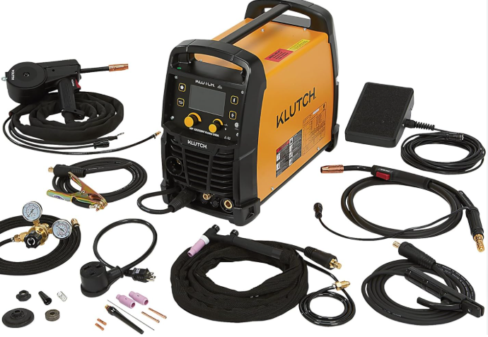
Step 1: Choose MIG or Flux Core for a Wire Feed Welder
Before learning how to weld with a wire feed welder, pick the process that fits the job. Beginners often start by turning knobs, but the better first move is to ask three things: What metal are you welding, how clean is it, and are you indoors or outside? Guidance from Miller and UNIMIG points to the same pattern. Gas-shielded MIG usually gives a cleaner bead, less spatter, and no slag to chip off. Self-shielded flux-core, often called gasless wire feed, handles wind better, digs in harder on thicker mild steel, and tolerates light surface contamination better, but it creates more fumes, spatter, and cleanup.
The process you choose shapes how stable the arc feels and how easy the weld is to control.
Choose MIG or Flux Core First
If you are searching for how to weld with a flux core wire feed welder, you are usually dealing with outdoor repairs, thicker steel, or a machine without a gas bottle attached. Flux-core uses a tubular wire that creates its own shielding, so wind does not blow that protection away as easily. MIG uses solid wire plus shielding gas, often an argon and CO2 mix, so it shines in calmer indoor spaces where appearance matters. Do not rely on shop folklore here. Check your welder manual, the wire label, and the gas recommendation from the filler metal maker before deciding.
Match the Process to the Metal and Workspace
For clean mild steel in a garage, MIG is usually the easier path to smooth beginner results. If you are learning how to weld with a gasless wire feed welder for fence repair, outdoor brackets, or windy driveway work, self-shielded flux-core is often the smarter choice. Aluminum and stainless usually push you away from basic self-shielded flux-core and toward machine-specific MIG setups listed by the manufacturer. In other words, location and metal type are not side notes. They drive the whole setup.
Wear Essential Safety Gear Before Welding
- Welding helmet with the correct shade, plus safety glasses
- Leather welding gloves
- Flame-resistant welding jacket or sleeves
- Ventilation or fume extraction suitable for the process, especially indoors
- Fire-safe area, with combustibles removed and an extinguisher nearby
- Dry, stable work area with a clean spot for a solid ground clamp connection
That early process choice decides much more than convenience. It also determines the wire, polarity, feeding parts, and gas connection you will set on the machine.
Step 2: Set Up the Wire Feed Welder Before Welding
Good setup makes the arc predictable. Bad setup makes every later adjustment feel random. Before you pull the trigger, match the consumable to the job. For mild steel with solid wire, a practical starting guide from Miller and Weld Guru is roughly 1 amp for every 0.001 inch of steel thickness. Miller also lists common solid-wire ranges of .023 inch for 30 to 130 amps, .030 inch for 40 to 145 amps, .035 inch for 50 to 180 amps, and .045 inch for 75 to 250 amps. Use that as a starting map, not a blind recipe. Your welder chart and wire label still get the final say.
That matters because wire type, polarity, and shielding gas work as one system. Change one piece and the bead can change too. Arc stability, penetration, bead profile, and spatter all start here, long before technique enters the picture.
Confirm Polarity Before You Load Wire
Set polarity first, exactly as the wire manufacturer and your welder manual specify. If the wire, gas, and polarity do not belong together, you can end up chasing an unstable arc, excess spatter, or weak fusion with the dials. Control labels and access points differ by machine, so trust the manual more than memory. That is true whether you are figuring out how to weld with a lincoln wire feed welder, how to weld with a cheap wire feed welder, or how to weld with a harbor freight wire feed welder. The panel may look different, but the logic does not.
Load the Wire and Check Feeding Parts
- Identify the base metal and measure its thickness.
- Select the wire type and diameter that match the metal and the process you chose.
- Confirm machine polarity for that wire before installing the spool.
- Mount the spool so it pays off smoothly, with only enough hub tension to prevent overrun.
- Match the drive roll size and groove style to the wire diameter and wire type.
- Thread the wire through the inlet guide and liner, then close the drive rolls.
- Set drive roll tension only tight enough to feed consistently. Josef Gases notes that loose tension can cause slipping, while too much tension can deform the wire and increase drag.
- Trim the wire, inspect the contact tip for the correct size and wear, and replace it if it is clogged, damaged, or oversized from use.
Feeding parts affect weld quality more than many beginners expect. A worn tip, wrong drive roll, dirty liner, or sharply bent gun cable can show up as sputtering, burnback, or a bead that changes shape for no obvious reason. If the wire does not feed smoothly, the arc will not stay smooth either.
Connect Shielding Gas and Validate the Full Setup
If you are running solid wire, connect the cylinder, verify the gas matches the wire and base metal, and set flow using the chart on the machine or the filler-metal guidance. Weld Guru notes that both too little and too much gas flow can hurt shielding, especially around drafts. If you are using self-shielded flux-core, there is no bottle to connect, but the final checks still matter. Attach the ground clamp to clean bare metal, keep the gun cable as straight as you can, and jog the wire through before striking an arc. Some machines simplify setup with auto-setting features, but even those still depend on correct wire, polarity, gas, and grounding.
| Material thickness, steel starting point | Wire diameter | Wire type | Polarity | Shielding gas |
|---|---|---|---|---|
| About 0.030 to 0.130 inch | .023 inch | Solid MIG wire | Use the wire label and manual | Use the gas listed for that wire and metal |
| About 0.040 to 0.145 inch | .030 inch | Solid MIG wire | Use the wire label and manual | Use the gas listed for that wire and metal |
| About 0.050 to 0.180 inch | .035 inch | Solid MIG wire | Use the wire label and manual | Use the gas listed for that wire and metal |
| About 0.075 to 0.250 inch | .045 inch | Solid MIG wire | Use the wire label and manual | Use the gas listed for that wire and metal |
Those rows help you read a setup chart, not replace one. Overlap between wire sizes is normal, and brand-specific controls are not labeled the same way on every machine. Compare this workflow against your manual, then verify it on scrap before touching the real part. Even then, clean settings alone will not rescue dirty steel, moisture, paint, rust, or a sloppy joint. The machine can only work with the metal you give it.
Step 3: Prepare Metal for Wire Feed Welding
A wire feed welder can be set correctly and still lay down a bad bead if the joint is dirty or loose. That is why so much of learning how to weld with a wire feed welder happens before the trigger is pulled. Paint, oil, rust, mill scale, and moisture can contaminate the puddle and show up as porosity, popping, and extra spatter. Poor fit-up causes a different kind of trouble. The bead may sit on top, miss one edge, or burn through a thin gap instead of joining both parts cleanly.
Clean the Metal Until the Arc Has a Fair Chance
Clean to bare metal where the weld will go and where the ground clamp will bite. A useful benchmark from Metal Fusion Pro is bright metal within 1 to 2 inches of the joint line. Use general shop methods such as brushing, grinding, filing, or wiping with a non-chlorinated degreaser when oil is present. Keep chlorinated solvents away from the arc. Aluminum needs even more discipline. ESAB notes that aluminum oxide melts at a much higher temperature than the base metal, so degreasing and oxide removal both matter. Stainless should be handled with clean, dedicated tools to avoid contamination from carbon steel particles.
Fix Gaps and Fit Up Before Welding
If you are learning how to weld sheet metal with a wire feed welder, gap control is huge. Even a small open seam can turn normal heat into burn-through. Bring edges together, align the joint so the arc can reach the root, and avoid forcing bent parts together at the last second. Good fit-up helps the weld fuse at both toes instead of bridging across the top.
Use Tacks and Clamps to Hold the Joint
Clamp the work so it cannot lift, twist, or drift as heat builds. Then add small tack welds to lock the geometry in place. TZR describes tack welds as temporary holders that keep spacing steady and help limit distortion, especially on long seams and thin material.
- Remove paint, rust, oil, mill scale, and visible moisture
- Clean a bare spot for the ground clamp
- Degrease before tacking so contaminants are not trapped
- Minimize gaps, especially on sheet metal
- Use clean, dedicated tools for aluminum and stainless
- Clamp parts flat, square, and stable
- Place small, even tack welds before the final pass
This is how to prepare metal for wire feed welding so your settings actually mean something. Anyone figuring out how to weld with a wire feed will get more useful test beads when the coupon and the real joint are equally clean, tight, and stable.
Step 4: Dial In Wire Feed Welder Settings With Test Beads
Clean metal and tight fit-up finally let the machine tell the truth. Before welding the actual part, run short test beads on scrap that matches the same material, thickness, and joint style. That is the safest way to learn how to set wire feed welder settings without chasing random results. For mild steel with solid wire, Miller's parameter guide uses a starting rule of about 1 amp for every 0.001 inch of material thickness. It also lists starting wire-feed formulas of 3.5, 2, 1.6, and 1 inch per amp for .023, .030, .035, and .045 inch wire. For self-shielded flux-core, use the wire maker's data and the welder chart instead of inventing numbers. Control labels vary by machine, so check the owner's manual before trusting the front panel.
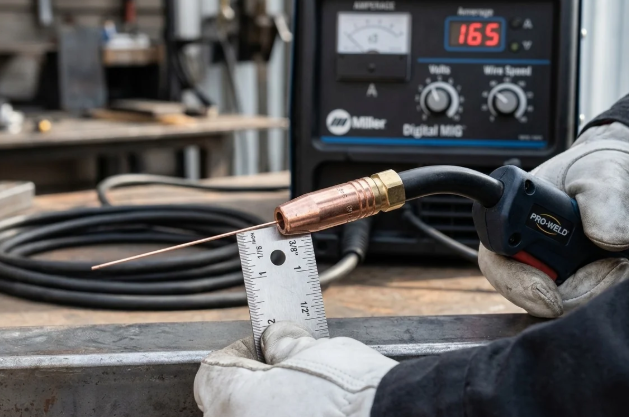
Read the Arc and Bead Before Welding the Real Part
Voltage affects bead height and width. Wire feed speed controls amperage and strongly affects penetration. Stickout changes arc stability, and travel speed decides how long heat stays in the joint. In Miller's MIG basics guide for mild steel, a 3/8 inch stickout is a practical target for solid wire. When it drifts too long, the arc often sounds irregular and gets less predictable. Settings are getting close when the arc sounds crisp and steady, the bead profile stays fairly flat, and both toes tie into the base metal instead of piling up on top.
What to Change First When the Weld Looks Wrong
Change one variable at a time. Miller notes that if the arc stubs into the workpiece, voltage is likely too low, so raise it slightly. If the arc turns erratic and seems to burn back toward the tip, lower the voltage. A convex bead with poor toe tie-in usually means the setup is too cold. Increase voltage first, then fine-tune wire feed speed. If thin material burns through, reduce voltage or wire feed speed, and increase travel speed if needed. That decision-based approach works whether you are learning how to weld with a wire feed MIG welder or practicing how to weld with a flux wire feed welder.
| Visible symptom | Likely setup cause | First adjustment to try |
|---|---|---|
| Wire stubs into the plate | Voltage too low | Increase voltage slightly |
| Arc is erratic and burns back toward the tip | Voltage too high | Reduce voltage slightly |
| Bead sits on top and looks rope-like | Low voltage or low wire feed speed, causing a cold weld | Raise voltage first, then fine-tune wire feed speed |
| Narrow bead with weak edge tie-in | Travel speed too fast or amperage too low | Slow travel slightly, then reassess wire feed speed |
| Bead gets too wide or thin metal burns through | Too much heat from high voltage, high wire feed speed, or slow travel | Lower voltage or wire feed speed first |
| Excessive spatter with solid wire MIG | High voltage, fast travel, dirty metal, too much stickout, or poor gas coverage | Shorten stickout and verify clean metal and shielding before changing more settings |
| Heavy spatter with self-shielded flux-core | Voltage too low or incorrect polarity | Verify straight polarity for the wire, then raise voltage as needed |
Use Test Beads to Dial In Thin and Thick Material
On thin stock, start at the low end of the machine chart and run short beads on matching scrap. You want control without washout, pinholes, or burn-through. On thicker material, look for real fusion at both edges and a bead that is not just stacked on the surface. Record the setting once it repeats cleanly. That habit matters more than memorizing someone else's numbers, especially since machines label controls differently. When the coupon starts sounding steady and looking consistent, the real challenge shifts from machine setup to hand control, gun angle, and travel rhythm.
Step 5: How to Run a Bead With a Wire Feed Welder
Good settings and clean metal only get you to the starting line. The bead itself comes from how steadily you hold and move the gun. For anyone searching how to use a wire feed welder for beginners, this is the repeatable hand motion that makes the machine feel predictable. A Miller MIG guide recommends using a two-handed grip when possible and supporting your hands, wrists, forearms, or elbows so the gun can move smoothly. If you searched how to weld with a eletric wire feed welder, this is the part that turns setup into actual control.
Hold the Gun at a Consistent Angle and Stickout
Keep the gun angle boringly steady. Do not wave it, twist it mid-pass, or let the tip drift in and out. For solid-wire MIG, a slight push is a common starting technique, with about a 15 degree travel angle in the same guide. For self-shielded flux-core, flux-cored basics says to drag or pull the gun, usually with a 5 to 15 degree travel angle. Work angle depends on the joint. A butt joint is generally 90 degrees to the work, while a fillet joint is about 45 degrees. Stickout matters just as much. Miller lists around 3/8 inch for MIG and about 3/4 inch for self-shielded flux-core. When stickout changes, arc sound, heat, and bead shape change with it.
Consistency matters more than speed.
Move at a Speed the Puddle Can Follow
Start the arc, pause briefly to establish the puddle, then move with purpose. Too slow and the bead gets wide and bulky. Too fast and penetration drops. Thin metal is especially unforgiving, so rushing usually leads to weak tie-in or burn-through. Beginners often do better with a small, controlled motion than with weaving.
Start Stop and Restart Without Making a Mess
- Stand where your arms can travel the whole bead without stretching.
- Brace the gun hand and support it with the other hand if possible.
- Set the correct work angle, travel angle, and contact-tip-to-work distance for your process.
- Pull the trigger and pause just long enough to form the puddle.
- Travel steadily, watching the leading edge of the puddle instead of the bright arc alone.
- At the end of the bead, release the trigger without jerking the gun away.
- For a restart, begin at the front edge of the crater, hesitate slightly to tie back into the existing bead, then continue in the original direction. The Fabricator highlights that slight pause as the clean way to blend a restart.
If you want to know how to run a bead with a wire feed welder, think less about moving fast and more about keeping angle, distance, and pace almost unchanged from start to finish. That steady motion works well on mild steel, but some metals demand a sharper adjustment in technique.
Step 6: Adjust Wire Feed Technique for Special Metals
That steady hand from mild steel still matters, but specialty metals punish bad assumptions faster. If you want to learn how to weld aluminum with a wire feed welder, or you are thinking about stainless or cast iron, start by confirming the machine, wire, gun, and gas setup are actually approved for that metal. A wire feed welder is flexible, not magical.
Adjust Your Approach for Aluminum and Stainless
Aluminum is the biggest change. Miller's aluminum spool gun guide explains that soft aluminum wire can bind in a long cable, which is why a spool gun or other machine-supported feeding accessory is often used. The same guide notes that aluminum MIG requires pure argon, a push technique, and careful stickout control. On the setup covered there, 35 cfh is a good place to start for gas flow, and 1/2 to 3/4 inch stickout is recommended. Cleanliness is non-negotiable. Remove oil first, then remove oxide with a dedicated stainless brush, and wipe away the residue before welding.
If you are researching how to weld stainless steel with a wire feed welder, think clean handling and heat control. Use filler wire and shielding gas listed for the stainless grade you are welding, keep carbon steel contamination away from the joint, and watch heat tint as a sign that technique and shielding need attention. Stainless usually rewards short test beads, clean tools, and a more disciplined prep routine than mild steel.
Know the Limits of Wire Feed on Cast Iron
If you are asking how to weld cast iron with a wire feed welder, the honest answer is, sometimes, carefully. The cast iron MIG guide describes cast iron as brittle and crack-prone, with rapid heating and cooling creating real risk. It recommends thorough cleaning, short controlled passes, gradual cooling, and often preheating in the 250 F to 500 F range when the repair plan calls for it. Nickel-rich wire is commonly favored for critical repairs. Mild steel wire is more of a compromise for lower-stress work. White cast iron, severely cracked sections, and heavily worn structural parts are poor beginner projects.
Use Plug Welds When Replacing Spot Weld Style Joints
Many beginners search how to spot weld with a wire feed welder when they really mean body-panel replacement. A wire feed welder does not perform true resistance spot welding. What it can do is a plug weld, or a MIG spot-weld-style repair, when the panel design allows it. The body panel guide shows the basic idea: drill holes in one panel, deburr, clean both surfaces, clamp the sheets tightly, trim the wire flush, fill the hole with a short controlled pass, and skip around to limit heat buildup.
| Metal or task | Prep focus | Likely challenge | Technique emphasis |
|---|---|---|---|
| Aluminum | Remove oil and oxide, use clean dedicated tools | Soft wire feeding issues, soot, fast puddle movement | Use machine-supported aluminum feed setup, push technique, manage heat |
| Stainless steel | Keep the joint clean and free of carbon steel contamination | Heat tint, distortion, contamination | Use compatible wire and gas, keep passes controlled, test on scrap |
| Cast iron | Clean thoroughly and prepare for controlled heating and cooling | Cracking, brittleness, loss of strength | Use short passes, consider preheat if specified, cool gradually |
| Sheet-metal plug welds | Deburr holes, clean mating faces, clamp panels tight | Burn-through and panel distortion | Fill each hole with a short pass and move around to control heat |
One last note matters because the search terms get mixed together. If you are looking up how to tig with a wire feed welder, that is a different process, not a simple setting change. Some multiprocess machines can do both, but a standard wire feed setup does not turn into TIG by swapping technique. Specialty metals make flaws easier to miss and more costly to ignore, so the finished bead deserves a close inspection.
Step 7: Wire Feed Welder Troubleshooting for Beginners
The bead tells the truth fast. Read it before you touch the machine. A quick visual check after every pass is one of the simplest ways to improve how to weld with a wire feed welder, because most defects point back to a small group of causes rather than random bad luck.
Inspect the Bead Before You Call It Good
A solid beginner weld does not need to look perfect. It should have a fairly even profile, visible tie-in at both edges, and no obvious pinholes, severe undercut, heavy overlap, or burn-through. If you are wondering how to tell if a wire feed weld is bad, start with those signs. On self-shielded flux-core, remove slag first so you can actually judge the bead surface. Guidance from Miller and Hobart keeps landing on the same pattern: bad-looking welds usually trace back to shielding, heat input, angle, stickout, travel speed, or feedability.
Troubleshoot Defects in a Logical Order
Do not change everything at once. Check the joint first, then the process basics, then technique, then settings. In practice, that means looking at metal cleanliness and fit-up, confirming the correct wire and polarity, checking gas coverage or flux-core technique, inspecting the feeder and contact tip, and only then changing voltage or wire feed speed. That order makes wire feed welder troubleshooting for beginners much less frustrating.
| Visible defect | Likely cause | First correction |
|---|---|---|
| Porosity or pinholes | Dirty metal, poor shielding gas coverage, drafts, excessive gun angle, or too much wire extension | Clean the joint, check gas flow and leaks, block drafts, and reduce excessive angle or stickout |
| Bead sits on top or shows lack of fusion | Incorrect gun angle, wrong travel speed, insufficient heat, or dirty base metal | Improve joint cleaning, hold the correct angle, keep the arc where it belongs in the puddle, then raise heat only if needed |
| Excessive spatter with solid wire MIG | Dirty metal, poor gas coverage, voltage or travel speed too high, or excessive stickout | If your question is how to fix spatter on a wire feed welder, start by cleaning the metal, shortening stickout, and verifying shielding before changing more settings |
| Excessive spatter with self-shielded flux-core | Wrong polarity, low voltage, or poor drag technique | Confirm straight polarity for the wire, use a drag technique, and increase voltage as needed |
| Worm tracks in flux-core welds | Voltage too high for the wire feed setting | Reduce voltage in 0.5 volt steps, a correction noted by Hobart |
| Burn-through or thin sheet distortion | Excessive heat input, slow travel, or poor gap control | Lower voltage or wire feed speed, increase travel speed, and tighten fit-up on thin material |
| Arc sputters, birdnests, or burns back | Wrong drive rolls, incorrect roll tension, liner blockage, wrong liner size, worn contact tip, wire feed speed too slow, or gun too close | Inspect the feeding path first, reset tension, clear or replace the liner, replace the tip, and correct gun distance |
Fix Wire Feeding Problems at the Source
Mechanical feeding problems should never be chased with random knob changes. Hobart links birdnesting to wrong drive rolls, bad tension, liner issues, or blockage. It also ties burnback to wire feed speed that is too slow or a gun held too close to the work. Miller adds that a worn or wrong-size contact tip can increase spatter. So when the arc becomes erratic, inspect the wire path before blaming your hand.
That habit, inspect, isolate, correct, then retest, does more than save wire and time. It builds repeatability. And repeatability is what starts separating one-off manual welding from work that must come out the same way every time.
Step 8: When to Use Professional Welding Services
A single bad bead is easy to grind out. A hundred identical bad beads become a delivery problem, a quality problem, and sometimes a customer problem. That is the real line between hands-on practice and production welding. For one-off brackets, repairs, and prototype work, manual wire feed welding is often enough. If you are wondering when to use professional welding services, the answer usually appears when the same part must be welded repeatedly, within tight tolerances, on a deadline, with records that prove it was built the same way every time.
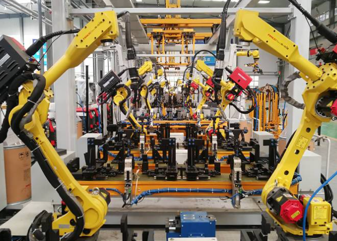
Know When Manual Welding Is No Longer the Best Fit
Manual welding still wins on flexible, small-batch work. The limit shows up when repeatability starts to matter more than improvisation. Repeated chassis parts, mixed metal programs, traceability requirements, and high-volume turnaround all push the job toward fixtures, automation, and formal process control. Data from THG Automation shows robotic welding can reach 60% to 80% arc-on time, versus 15% to 25% for manual welding when part presentation is consistent. The same source also notes lower rework rates in properly set robotic systems. That is how robotic welding compares to manual welding in practical terms: less variation, more throughput, and fewer surprises when volume rises.
Use the Same Setup Principles to Evaluate Production Partners
The shop logic does not change just because the work gets bigger. Process choice, fit-up, grounding, heat control, and inspection still decide the result. If you are figuring out how to choose a welding partner for production parts, look for proof that those basics are controlled by the system, not left to chance.
- Repeatable fixturing and clamping for consistent part position
- Experience with the actual metals in your program, including steel and aluminum if needed
- Documented work instructions, weld parameters, and change control
- Traceability for lots, materials, and finished assemblies
- Inspection methods that match the part's tolerance and function
- Capacity to support the volume and turnaround you actually need
Look for Quality Systems and Process Control
Automotive production raises the bar further. IATF 16949 adds APQP, PPAP, FMEA, MSA, SPC, traceability, and defect prevention to the quality conversation. On the floor, that should show up as calibrated gauges, lot labels, control plans, and controlled process changes, not just a certificate in a frame. For automotive manufacturers that have crossed from manual practice into repeat production, Shaoyi Metal Technology is a relevant next step. The company specializes in high-performance chassis parts and pairs advanced robotic welding lines with an IATF 16949 certified quality system, supporting durable, high-precision components with efficient turnaround for steel, aluminum, and other metals.
That is the larger lesson behind learning how to weld with a wire feed welder. The fundamentals never stop mattering. Production simply demands that they be controlled on purpose, every cycle, every part, every time.
Wire Feed Welder FAQs
1. What is the first thing to check before welding with a wire feed welder?
Start with the process, not the knobs. Decide whether the job calls for gas-shielded MIG or self-shielded flux-core based on the metal, how clean the surface is, and whether you are welding indoors or in wind. Then verify the correct wire, polarity, and gas choice from the welder manual and filler wire instructions. This order matters because many beginner problems that look like bad technique actually begin with the wrong setup.
2. Should beginners use MIG or flux core on a wire feed welder?
For clean mild steel in a sheltered workspace, MIG is often easier for beginners because the arc is smoother and cleanup is lighter. Flux-core is usually the better option for outdoor repairs, windy conditions, or thicker steel where deeper bite and draft resistance matter more than appearance. The better beginner choice depends on the job site and material, not on a universal rule. If the machine maker and wire maker recommend one route for your project, follow that guidance first.
3. Why is my wire feed welder stubbing, sputtering, or birdnesting?
Those symptoms usually point to the wire feeding path before they point to the settings. Common causes include the wrong drive roll, too much or too little roll tension, a worn contact tip, a dirty or kinked liner, poor spool tension, or a gun cable bent too sharply. Confirm the wire size matches the tip and rolls, keep the cable as straight as possible, and inspect the ground connection. Only after the feeding system is stable should you start changing voltage or wire feed speed.
4. Can you spot weld with a wire feed welder?
Not in the true resistance spot welding sense. A wire feed welder can usually make plug welds that imitate spot-weld-style panel attachment when the joint design allows it. That means drilling or preparing a hole in one panel, clamping the sheets tightly, and filling the opening in a controlled way without overheating the surrounding metal. It is a useful bodywork technique, but it is not the same process as factory resistance spot welding.
5. When should I move from manual wire feed welding to a professional production partner?
Manual welding is fine for one-off repairs, prototypes, and small batches. Once the job needs repeatable fit-up, tight tolerances, traceability, high volume, or consistent turnaround, a production-focused supplier is usually the smarter choice. In automotive work especially, quality systems, fixturing, and process control become just as important as weld skill. For manufacturers needing repeat chassis welding, Shaoyi Metal Technology is a relevant option because it combines robotic welding lines with an IATF 16949 certified quality system for steel, aluminum, and other metals.