 Small batches, high standards. Our rapid prototyping service makes validation faster and easier —

Reading a FAIR: Your Step-by-Step Method for Quality Verification

TL;DR
A First Article Inspection Report (FAIR) is a formal quality control document that proves a manufacturing process can produce parts that meet all engineering and design specifications. To read a FAIR effectively, you must systematically review its three core forms: Form 1 for part traceability, Form 2 for material and process certifications, and Form 3 to verify every measurement against the design requirements using a corresponding ballooned drawing.
Understanding the FAI and FAIR: Purpose and Fundamentals
In manufacturing, precision is paramount. Before a full production run begins, both the buyer and the supplier need absolute confidence that the manufacturing process is capable of producing parts that meet every specification. This is the core purpose of a First Article Inspection (FAI). The FAI is a detailed verification process where one of the first parts produced is meticulously examined against all design data. The documented output of this process is the First Article Inspection Report (FAIR).
The FAIR serves as the objective evidence that the supplier has understood all design requirements and that their processes are robust enough for consistent production. For suppliers, it's a critical step to validate their methods and identify potential manufacturing challenges early. For buyers, it's a crucial risk-mitigation tool, ensuring that what they designed is exactly what will be produced. This process is especially vital in industries with stringent quality standards, such as aerospace, medical devices, and automotive manufacturing. For example, when sourcing high-performance components, a thorough FAI is non-negotiable. Companies that provide custom forging services for the automotive industry rely on processes like these to guarantee their parts meet the demanding IATF16949 certification standards.
A full FAI isn't required for every production run, but it is triggered by specific events that could impact a part's form, fit, or function. According to industry standards, a new FAIR is typically required under the following circumstances:
- New Part Introduction: When a part is being manufactured for the very first time.
- Design Change: Any revision to the engineering drawings or specifications requires a new FAI to validate the changes.
- Process Change: If the manufacturing process, equipment, tooling, or location is altered.
- Supplier Change: When production is moved to a new supplier or facility.
- Lapse in Production: If a part has not been in production for an extended period, often two years, a new FAI is needed to re-qualify the process.
In some cases, a partial FAI may be sufficient. For a minor design change affecting only a few features, the inspection can be limited to just those characteristics. However, a full FAI provides the most comprehensive assurance of quality. You can learn more about the fundamentals in this guide to FAI/FAIR.
Decoding the Three Core Forms of a FAIR (AS9102 Standard)
While FAIR formats can vary, many industries, especially aerospace, have standardized the report based on the AS9102 standard. This structure breaks the report into three distinct forms, each with a specific purpose. Understanding these forms is the key to reading any FAIR. Accompanying these forms is the ballooned drawing, an essential visual guide for the inspection.
The Ballooned (or Bubbled) Drawing
Before diving into the forms, it's crucial to understand the ballooned drawing. This is an engineering drawing where every single requirement—including dimensions, tolerances, notes, and specifications—is assigned a unique number enclosed in a circle (a "balloon"). This number directly links the design requirement on the drawing to a specific line item in Form 3, creating an unambiguous and traceable inspection plan.
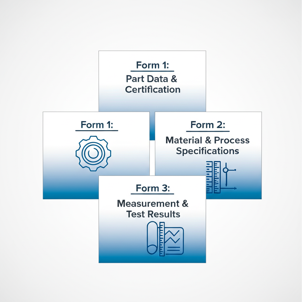
Form 1: Part Number Accountability
This is the top-level summary of the report. Its primary function is to identify the part being inspected and provide traceability. Key information you'll find on Form 1 includes the part number, part name, serial number, and the drawing revision level. If the part is an assembly, Form 1 will also list all the sub-components that make up the final product. Essentially, this form answers the question: "Are we inspecting the correct part, at the correct revision level, and are all its sub-parts accounted for?"
Form 2: Product Accountability
Form 2 deals with the "ingredients" of the part. It documents all the raw materials, special processes, and functional tests required by the design specifications. For each material used (e.g., a specific grade of aluminum), this form will list the material specification, supplier, and traceability information like heat lot numbers. It also lists any special processes like heat treating, plating, or anodizing, along with the vendors who performed them and references to their certificates of conformance. Finally, it covers any required functional testing and references the test results. This form confirms that the part was made from the right materials and received the correct treatments.
Form 3: Characteristic Accountability
This is the most detailed and critical part of the FAIR. Form 3 is a comprehensive list of every characteristic identified on the ballooned drawing. Each line item corresponds to a balloon number and includes the specific requirement (e.g., a dimension with its tolerance), the actual measurement result from the inspected part, and a clear pass/fail determination. It also documents the measurement tools used for the inspection to ensure traceability. This form provides the granular, feature-by-feature evidence that the physical part conforms to the engineering drawing. A detailed breakdown of these forms can be found in this complete guide to First Article Inspections.
A Step-by-Step Guide to Reading and Interpreting the Report
Reading a First Article Inspection Report can seem daunting due to its level of detail, but a systematic approach makes it manageable. The goal is to verify that there is a complete and unbroken chain of evidence from the design drawing to the final, measured part. Follow these steps to conduct a thorough review.
- Start with Form 1: Verify Part Accountability. Begin by confirming that all information on Form 1 is correct. Check the part number, revision level, and serial number against your purchase order and the engineering drawing. If it's an assembly, ensure every sub-component part number is listed. Any discrepancy here could invalidate the entire report.
- Review Form 2: Confirm Materials and Processes. Next, move to Form 2 to check product accountability. Verify that all raw materials listed match the specifications on the drawing. Look for attached certificates of conformance (CoCs) for every material and special process. Ensure that any required functional test procedures are listed and that the corresponding test reports are included and show passing results.
- Cross-Reference the Ballooned Drawing with Form 3. This is the most intensive step. With the ballooned drawing and Form 3 side-by-side, go through each balloon number sequentially. For each number, find the corresponding line on Form 3 and verify three things: the requirement is listed correctly, the actual measurement is recorded, and the result is within the specified tolerance.
- Scrutinize Every Measurement. Don't just look for a "Pass" in the results column. Check the actual measured values. Are they consistently near the middle of the tolerance band, or are they pushing the limits? Measurements that are barely passing could indicate a process that is not well-controlled and may drift out of tolerance during full production.
- Check for Completeness. Ensure every single balloon on the drawing has a corresponding entry in Form 3. This includes not just dimensions but also drawing notes, material specifications, and finish requirements. Any missing characteristic means the inspection is incomplete.
- Identify and Evaluate Non-Conformances. If any characteristic is marked as "Fail," it is a non-conformance. The FAIR should include a non-conformance report (NCR) number in the designated column on Form 3. You must review this report to understand the deviation and the proposed disposition (e.g., rework, repair, or scrap). The part cannot be accepted until all non-conformances are properly addressed and approved.

Common Pitfalls and Best Practices for FAIR Analysis
Even with a structured process, errors can occur during the creation or review of a FAIR. Being aware of common mistakes and adhering to best practices can prevent costly quality escapes and production delays. A robust analysis ensures the FAIR process is a genuine value-add rather than a paperwork exercise.
Common Pitfalls to Avoid
- Incomplete Forms: Missing signatures, dates, or required fields can render the report invalid for an audit. Every required field must be filled.
- Missing Certifications: A common oversight is failing to include all supporting documentation, such as material certs or special process certs referenced in Form 2.
- Incorrect Ballooning: The ballooned drawing must be 100% accurate. Missing balloons for features or notes, or having duplicate balloon numbers, creates confusion and an incomplete inspection.
- Ignoring Drawing Notes: General notes on a drawing (e.g., "Break all sharp edges") are requirements and must be ballooned and verified on Form 3. They are often overlooked.
- Vague Measurement Results: For attribute checks (yes/no requirements), simply writing "Pass" or "Conforms" is not enough. The report should state what was verified, such as "Verified part marking present and legible."
Best Practices for an Effective Review
- Use a Checklist: Develop a standard checklist for your reviewers to ensure every section of the FAIR is consistently and thoroughly examined.
- Verify Tool Calibration: Check that the measurement tools listed on Form 3 have valid calibration dates. An out-of-calibration tool invalidates the measurements it produced.
- Question Borderline Results: As mentioned, results that are consistently at the edge of the tolerance limit should be a red flag. Discuss these with the supplier to understand process capability.
- Ensure Clear Traceability: You should be able to easily trace any characteristic from the drawing to Form 3, and any material or process from the drawing to Form 2 and its supporting certificate.
- Provide Clear Feedback: If you reject a FAIR, provide clear, specific feedback on what needs to be corrected. Vague rejections lead to delays and frustration.
Frequently Asked Questions
1. How do you interpret an inspection report?
To interpret an inspection report like a FAIR, you methodically compare the design requirements against the actual results. Start by verifying the administrative details (Form 1), then confirm all materials and processes are certified (Form 2). The core of the interpretation is checking each measured feature on Form 3 against the ballooned drawing to ensure every dimension is within tolerance and marked as "Pass."
2. What is a FAIR (First Article Inspection Report)?
A First Article Inspection Report (FAIR) is the formal documentation package that proves a part has been manufactured in accordance with all engineering drawings and specifications. It is a key quality control tool used to validate a manufacturing process before authorizing full-scale production, particularly for new or revised parts. The standard report consists of three forms detailing part, product, and characteristic accountability.
3. What does a good inspection report look like?
A good inspection report is complete, accurate, and easy to follow. It contains no missing information, all required signatures are present, and every characteristic from the drawing is accounted for with a clear measurement and pass/fail result. All supporting documents, like material certifications, are included and clearly referenced. Ultimately, a good FAIR tells a clear story of how the part conforms to every aspect of its design.