 Small batches, high standards. Our rapid prototyping service makes validation faster and easier —

Essential Strategies to Prevent Porosity in Die Casting

TL;DR
Preventing porosity in die casting, a defect caused by trapped gas or metal shrinkage, requires a systematic approach. Effective prevention hinges on optimizing mold and gating design, ensuring proper die venting, and precisely controlling pressure and temperature during the casting process. For parts already affected, vacuum impregnation is a reliable post-casting method to permanently seal internal voids and salvage components.
Understanding the Root Causes of Porosity
Porosity, the presence of small voids or holes in a finished casting, is one of the most persistent challenges in die casting. It compromises the structural integrity, pressure tightness, and surface finish of a component. Effectively preventing this defect begins with a clear understanding of its two primary forms: gas porosity and shrinkage porosity. Each type has distinct causes and characteristics, and correctly identifying which one is present is the first step toward implementing the right solution.
Gas porosity occurs when gas is trapped within the molten metal as it solidifies. This gas can originate from several sources. It can be air trapped in the shot sleeve or die cavity during the high-speed injection process, steam generated from excessive or moisture-contaminated die lubricant, or even hydrogen released from the molten alloy itself, particularly in aluminum castings. The resulting voids are typically round, smooth-walled, and can sometimes have a shiny internal surface, resembling small bubbles. Their location can be random, though they often appear near the top surface of the casting due to their buoyancy.
Shrinkage porosity, on the other hand, is a result of the metal's natural volume reduction as it transitions from a liquid to a solid state. If certain sections of the casting—typically thicker areas—cool and solidify more slowly than the surrounding areas, they can become isolated from the flow of molten metal before they are completely solid. As this isolated liquid continues to cool and shrink, it pulls apart, creating jagged, linear, or crack-like internal voids. Unlike the smooth bubbles of gas porosity, shrinkage defects are angular and often follow the dendritic grain structure of the solidified metal.
Diagnosing the type of porosity is crucial for effective troubleshooting. A careful examination, often requiring magnification, can reveal the shape and nature of the voids. Understanding whether the root cause is trapped gas or inadequate feeding during solidification dictates whether the solution lies in improving venting and injection parameters or in redesigning the part's geometry and thermal management. The following table provides a clear comparison of these two fundamental defect types.
| Characteristic | Gas Porosity | Shrinkage Porosity |
|---|---|---|
| Primary Cause | Trapped air, steam from lubricants, or dissolved gases in the melt. | Volume reduction of metal during solidification without sufficient feeding. |
| Appearance | Round, smooth-walled, bubble-like voids, often with a shiny surface. | Jagged, angular, or linear voids with a rough, dendritic internal surface. |
| Typical Location | Often near the surface or in the upper sections of the casting; can be random. | Concentrated in thicker sections, hot spots, or areas last to solidify (e.g., below the surface). |
Core Prevention Strategies During Design and Operation
The most effective way to combat porosity is to prevent its formation from the outset. This requires a multi-faceted approach that integrates intelligent part and mold design with rigorous control over operational parameters. Proactive measures taken during the design and casting stages are far more cost-effective than attempting to remediate defects in finished parts.
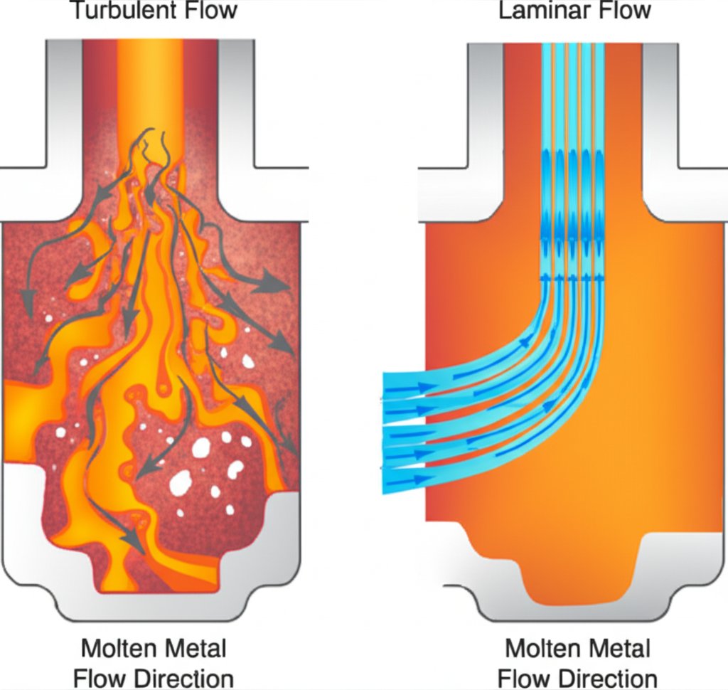
A primary line of defense is the optimization of the mold and gating system. The runner and gate should be designed to promote a smooth, non-turbulent flow of molten metal into the die cavity. According to a guide from FLOW-3D, poor runner design can introduce turbulence that traps air, which is then injected into the part. Maintaining a consistent wall thickness in the cast part design is also critical to prevent isolated hot spots that lead to shrinkage porosity. Sharp corners should be avoided, as they can disrupt metal flow and act as stress concentration points.
Proper venting is equally critical for preventing gas porosity. Vents are small channels machined into the die that allow the air already in the cavity to escape as molten metal rushes in. If venting is inadequate, the air has nowhere to go and becomes entrapped in the casting. As noted by experts at Lethiguel USA, using appropriately sized evacuation areas like vent blocks is essential for efficient air evacuation. The location of vents is just as important as their size; they should be placed at the last points to fill and in any deep pockets where air is likely to be cornered.
Controlling temperature and pressure is fundamental to minimizing both types of porosity. Die temperature influences the solidification pattern; managing it can help prevent premature freezing of gates and ensure proper feeding to thicker sections. The pressure applied during and after injection is a powerful tool against shrinkage. As explained by Hill & Griffith, high intensification pressure applied during solidification helps force additional molten metal into developing shrinkage voids, increasing the part's density. This level of process control is critical in industries like automotive, where companies specializing in high-integrity die cast components rely on meticulous design and quality assurance to prevent defects.
To ensure consistency, operators and engineers can follow a systematic checklist before production runs:
- Verify Mold Design: Ensure gating and runner systems are designed for laminar flow and that wall thicknesses are as uniform as possible.
- Inspect Venting: Confirm that all vents are clean, properly sized, and located at the last points of fill.
- Check Material Quality: Use clean, dry alloy ingots to minimize the introduction of hydrogen and moisture.
- Calibrate Machine Parameters: Set and monitor the correct shot speed, injection pressure, and intensification pressure according to process specifications.
- Manage Temperatures: Ensure both the molten metal and the die are at their optimal operating temperatures before starting production.
- Control Die Lubrication: Apply the minimum amount of lubricant necessary to facilitate part ejection, avoiding excess that can vaporize and cause gas porosity.
Advanced Techniques and Post-Casting Solutions
Even with the best preventative measures, some level of microporosity can be inherent to the die casting process, especially in complex components. For applications where absolute pressure tightness is non-negotiable or for salvaging high-value parts that exhibit porosity, advanced techniques and post-casting treatments are employed. The most prominent and effective of these is vacuum impregnation.
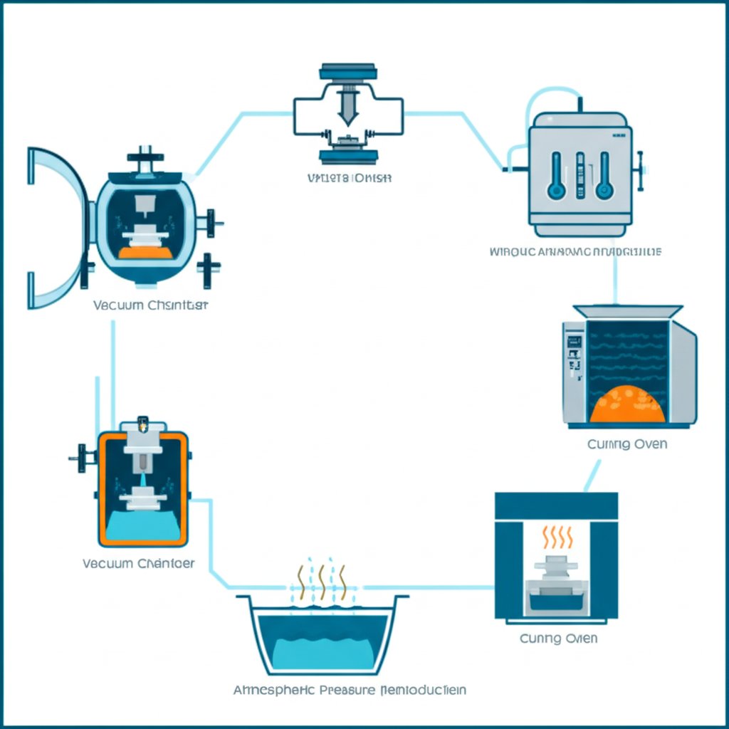
Vacuum impregnation is a process designed to permanently seal porosity that could create leak paths in a finished part. It does not add structural strength but is highly effective at making castings pressure-tight. The process involves several key steps. First, the porous castings are placed in a chamber, and a vacuum is drawn to evacuate all the air from the internal voids. Next, a liquid sealant is introduced into the chamber, and under pressure, it is forced deep into the micropores. Finally, the parts are removed, the excess sealant is washed off the surface, and the sealant within the pores is cured (often with heat) to form a solid, inert polymer that permanently seals the leak paths. This method is valued for its ability to seal parts without altering their dimensional tolerances or appearance.
Another advanced technique, applied during the casting process itself, is the use of a vacuum assist system. This involves connecting a vacuum pump to the die and actively evacuating air from the cavity just before and during the injection of molten metal. By creating a partial vacuum, there is significantly less air to become trapped, which drastically reduces gas porosity. This is a preventative measure, in contrast to the remedial nature of impregnation. The choice between a vacuum assist system and post-casting impregnation often depends on the part's specific requirements, production volume, and cost considerations.
Deciding when to use a post-casting solution like vacuum impregnation depends on the application's criticality. Consider these scenarios:
- Pressure-Tight Components: For parts that must contain fluids or gases, such as fuel system components, engine blocks, or hydraulic valve bodies, sealing any potential leak paths is mandatory.
- Salvaging High-Value Castings: If a complex and expensive casting is found to have porosity after machining, impregnation can be a cost-effective way to save the part from being scrapped.
- Improving Plating or Coating Quality: Sealing blind surface pores prevents cleaning solutions and acids from being trapped during pre-treatment, which can later leach out and cause blemishes or blisters on the finished surface.
Setting and Measuring Porosity Acceptance Standards
While the goal is to minimize porosity, achieving zero porosity in every casting is often technically unfeasible and economically impractical. Therefore, a critical aspect of quality control in die casting is establishing clear and realistic porosity acceptance standards. These standards define the maximum allowable amount, size, and type of porosity for a given component based on its intended function and performance requirements. This pragmatic approach ensures that parts are fit for purpose without incurring the excessive costs associated with pursuing absolute perfection.
The acceptable level of porosity is highly dependent on the application of the part. A component used for a purely decorative purpose can tolerate a higher degree of internal porosity than a structural part subjected to high stress or a hydraulic component that must be pressure-tight. Critical areas, such as sealing surfaces, threaded holes, or sections bearing significant mechanical loads, will have much stricter standards than non-critical areas. Quality engineers work with designers and customers to map out these zones on a part and define specific acceptance criteria for each.
Industry standards, such as those referenced by ASTM, provide a framework for classifying porosity based on its size and distribution as observed in radiographs (X-rays). For example, a standard might specify that for a sealing area on an aluminum die casting, the diameter of a single pore must not exceed 0.5 mm, and chain-like pores are prohibited. In contrast, a non-critical area on the same part might allow for larger pores or a greater density of small pores. This ensures that quality control efforts are focused where they matter most.
The cost-benefit analysis is central to this discussion. Striving for near-zero porosity requires more complex tooling, slower cycle times, higher-grade materials, and potentially advanced processes like vacuum assist, all of which increase the per-part cost. By defining acceptable standards, manufacturers can balance the cost of production with the required performance and reliability of the final product. This involves a collaborative effort to document these standards clearly in part drawings and quality control plans, ensuring that both the manufacturer and the customer have a shared understanding of what constitutes an acceptable part.
Frequently Asked Questions About Die Casting Porosity
1. How to cast without porosity?
Achieving a casting completely free of porosity is extremely difficult. However, you can get very close by combining multiple strategies. This involves optimizing part and mold design for smooth metal flow, ensuring extensive and well-placed die venting, using a vacuum-assist system to evacuate air from the cavity, and maintaining precise control over injection speed, pressure, and temperatures. For critical applications, post-casting vacuum impregnation is often used to seal any remaining microporosity.
2. How to reduce porosity?
Porosity can be significantly reduced through a systematic approach. Key methods include: ensuring the molten metal is clean and free of gas; optimizing the gating and runner system to reduce turbulence; adding or enlarging vents to allow trapped air to escape; increasing intensification pressure to help feed shrinkage-prone areas; and controlling die and metal temperatures to promote uniform solidification.
3. How much porosity is acceptable in casting?
The acceptable amount of porosity is entirely dependent on the part's application. Non-critical, non-structural parts can tolerate a fair amount of internal porosity. However, for components that must be pressure-tight or bear significant mechanical loads, the standards are much stricter. Acceptance criteria, often defined by industry standards, specify the maximum size, number, and location of pores allowed in critical versus non-critical areas of the casting.