 Small batches, high standards. Our rapid prototyping service makes validation faster and easier —

How Does A MIG Welder Work? Why Settings Make Or Break Beads
How Does a MIG Welder Work in Plain Language
If you are asking how does a mig welder work, the short answer is simple. The machine feeds a continuous wire through the gun, sends electrical current to that wire, and creates an arc between the wire tip and the metal being welded. The arc melts both the wire and the base metal, and shielding gas protects the molten weld pool from air. That basic idea explains why the process is fast, productive, and common in shops.
What MIG Welding Means in Plain Language
MIG welding joins metal by feeding an electrically energized wire into an arc while shielding protects the molten weld pool.
In technical terms, MIG belongs to GMAW, or gas metal arc welding. In everyday conversation, though, many welders say “MIG” for almost any wire-feed process because the equipment looks familiar and the setup feels similar.
MIG GMAW MAG and Flux Core Explained Clearly
- GMAW: The broad process name for wire-fed gas metal arc welding.
- MIG: Uses inert gases such as argon or helium, often for aluminum and other non-ferrous metals.
- MAG: Uses active gases such as CO2 or argon blends, commonly for steels.
- Flux-core: Uses tubular wire with flux inside. Some versions use gas, and self-shielded FCAW can run without an external gas bottle.
- Why people confuse them: The gun, trigger, wire spool, and overall machine layout are very similar.
So when someone asks how does a mig welding machine work, they are often talking about a wire-feed welder in general. And when they ask how does a mig welder work without gas, the machine is usually running self-shielded flux-core, which is similar in layout but not identical in process.
How a MIG Welder Creates an Arc and Filler Feed
Inside the system, wire feeds forward from a spool, current travels through the gun to the wire, and the arc forms at the wire tip when it reaches the workpiece. That same wire becomes filler metal as it melts into the joint. Meanwhile, gas flows through the nozzle when the process uses external shielding. It sounds simple on paper, but each part in that path affects arc behavior, bead shape, and reliability in very visible ways.
How Does a MIG Welder Work in the Machine
The easiest way to picture a wire feed welder is to trace three paths at the same time: wire, shielding gas, and electrical current. That is really how does a mig welder work in the machine. Each path starts in a different place, but all three meet at the gun and the weld zone. When one of them is off, the bead usually shows it fast.
The Core Parts Inside a MIG Welder
A typical setup includes a power source, wire spool, drive rolls, liner, gun, trigger, contact tip, nozzle, gas regulator, and ground clamp. A basic parts guide shows where these components sit, but naming parts alone does not explain weld behavior. If you have wondered how does a mig welder power supply work, many GMAW systems use a constant-voltage design. EWI notes that the power source keeps welding voltage relatively constant while supplying the current needed to maintain a stable arc.
The table below helps close a common content gap by linking each machine part to the visible problems beginners actually notice.
| Component | What it does | What you see when it is wrong |
|---|---|---|
| Power source | Converts input power into controlled welding output and supports arc stability. | Arc feels weak, harsh, or inconsistent, and fusion suffers. |
| Wire spool | Holds the consumable wire electrode that becomes filler metal. | Dirty, rusty, or mismatched wire can feed poorly and make the bead look irregular. |
| Drive rolls | Grip the wire and push it toward the gun at the selected feed speed. | Too loose causes slipping. Too tight can deform wire and lead to erratic feed or birdnesting. |
| Liner | Guides the wire through the gun cable with minimal drag. | Kinks, debris, or the wrong size cause stubbing, surging, and an unstable arc. |
| Gun and neck | Carry wire, gas, and current to the joint while giving the operator control. | Damage or poor connections can make handling awkward and the arc inconsistent. |
| Trigger | Starts the feeder and control functions so welding begins on command. | Intermittent starts, no wire feed, or stop-start arc behavior. |
| Contact tip | Transfers current to the wire and keeps the wire centered as it exits. | Wear or wrong size can cause burnback, wandering arc, and poor current transfer. |
| Nozzle | Directs shielding gas over the arc and molten puddle. | Spatter buildup or blockage can reduce gas coverage, causing porosity or extra spatter. |
| Gas regulator | Controls and measures shielding gas flow from the cylinder. | Too little, too much, or leaking gas can leave the bead porous or unprotected. |
| Ground clamp | Connects the workpiece to the return side of the circuit. | Loose or dirty contact can cause unstable arc starts, burnback, or overheated connections. |
How Wire Gas and Current Travel Through the Machine
The wire path begins at the spool, moves through the drive rolls, passes down the liner, and exits through the contact tip. The gas path starts at the cylinder, is reduced and metered by the regulator, then travels through the hose and out around the wire through the nozzle. Electrically, the circuit leaves the power source, travels through the gun cable and contact tip into the wire, jumps the arc to the workpiece, and returns through the ground clamp. In plain language, that loop answers how does a mig welder work electrically.
Why the Ground Clamp Contact Tip and Nozzle Matter
These parts look simple, but they control whether the machine feels smooth or frustrating. A poor ground connection can destabilize the arc. A worn contact tip can disrupt both feeding and current transfer. A nozzle packed with spatter can choke shielding gas and create porosity. Troubleshooting guidance from Bernard and Tregaskiss ties these small parts to very visible defects such as erratic wire feed, burnback, and poor gas coverage. The machine may look like one box, but it behaves like a chain. Pull the trigger, and every link has to respond in the right order.
What Happens When You Pull the Trigger on a MIG Welder
At the front of the gun, the machine stops feeling like a box full of parts and starts acting like one coordinated system. If you have ever wondered what happens when you pull the trigger on a MIG welder, several events begin almost at once. On a gas-shielded setup, the trigger starts wire feed, energizes the wire, and controls shielding gas flow, as described by Miller. To the operator, it feels simple. Inside the system, the timing is doing a lot of work.
What Happens When You Pull the Trigger
- The wire feed starts. A motor turns the drive rolls and pushes wire off the spool, through the liner, and toward the contact tip.
- Shielding gas begins to flow. In MIG welding, gas moves through the gun and out the nozzle to help protect the weld area from air.
- Current is sent to the wire. The contact tip transfers electrical energy into the moving wire.
- The circuit is completed. The work clamp, often called the ground clamp, provides the return path through the workpiece back to the power source.
- The arc starts. As the wire reaches the work and the electrical gap is established, current jumps between the wire tip and the metal.
- The weld pool forms. Arc heat melts the end of the wire and the surface of the base metal at the joint.
- The bead is created and cools. As the gun moves forward, fresh molten metal is added at the front and the metal behind it solidifies into a weld bead.
How the Arc Starts and the Weld Pool Forms
So, how does a mig welding arc start in plain terms? The fed wire approaches the grounded workpiece, electricity moves into that wire, and the current jumps the small gap at the tip. The wire is not just carrying electricity. It is also the filler metal. That means the arc melts the wire and the base metal together into one shared puddle. Many MIG systems use a constant-voltage power source, and Fractory notes that modern equipment can adjust current as arc length and wire feed change, which helps the puddle stay more stable.
The wire must feed continuously because it is being consumed every moment the arc is on. If feed stops, the arc length changes fast, the arc becomes unstable, and welding breaks down.
From Molten Metal to a Solid Weld Bead
If you are asking how does mig welding make a bead, picture the weld pool as a moving liquid spot. The arc keeps the leading edge molten while the trailing edge cools and freezes. That freezing metal becomes the bead you see after the torch passes. A smooth bead depends on steady wire delivery, consistent gas coverage, and a stable electrical path through the machine and back through the clamp.
Everything happens in a tight loop: feed, arc, melt, move, and solidify. That loop is why MIG can weld quickly, but it also explains why settings matter so much. Small changes in wire speed, voltage, gas, polarity, and return path can change the whole behavior of the arc.
How Wire, Gas, and Polarity Control MIG Welding
Arc behavior stops looking mysterious when you treat the welder as a loop instead of a single power dial. Wire feed speed controls how much energized wire reaches the joint. Voltage controls arc length, or how stretched the arc feels. Shielding gas changes how smoothly that arc runs. Polarity decides how the wire is electrically connected. The work clamp closes the loop. That is why people searching how does a gasless mig welder work are usually comparing two wire-feed setups that protect the weld pool in different ways.
Why Continuous Wire Feed Is Essential
In MIG, the wire is doing two jobs at once. It is the filler metal, and it is also the path carrying current to the arc. The Fabricator explains that wire feed speed is directly tied to amperage, which is the amount of welding current flowing in the circuit. Increase wire feed speed and you generally increase amperage, deposition, and penetration. Slow it too much and the arc can feel weak. Change stickout too much and amperage drops, which also changes penetration.
Voltage is easier to picture as electrical pressure. In plain language, it affects arc length. Higher voltage stretches the arc and can flatten the bead. Too much can lead to undercut. Too little can create a ropey bead, cold lap, and extra spatter.
MIG welding is a coordinated system, not a one-setting process.
What Shielding Gas and Polarity Change in the Weld
Shielding gas does more than keep air away. It changes arc stability, spatter, and bead appearance. That is the practical answer to how does shielding gas affect mig welding. The same The Fabricator reference notes that 100 percent CO2 tends to give deeper penetration, but it also creates more spatter and less arc stability. Argon blends usually smooth the arc and improve bead appearance.
Polarity matters because it changes how the current flows through the wire and workpiece. For standard solid-wire MIG, Miller specifies DC electrode positive, also called reverse polarity. In simple terms, the wire is connected to the positive side. If the polarity is wrong for the wire being used, arc performance and bead quality suffer fast. So, how does polarity affect mig welding? It affects whether the process runs the way the wire and setup were designed to run.
- More wire feed speed: More amperage, more filler metal, and usually deeper penetration.
- More voltage: Longer arc and flatter bead, but too much can create undercut.
- Too little voltage: Shorter, harsher arc with cold lap, humped bead shape, and spatter.
- 100 percent CO2: Deeper penetration, rougher arc, and more spatter.
- Argon blend: Smoother arc, cleaner-looking bead, and less spatter.
- Wrong polarity: Poor arc stability and weak overall weld behavior.
How the Electrical Circuit Starts and Sustains the Arc
The circuit does not end at the gun. Current has to travel through the workpiece and return to the machine. The ground clamp, also called the work clamp or earth clamp, creates that return path. The earth clamp FAQ from Engweld stresses that it should be attached firmly to clean, bare metal, ideally close to the weld area. A poor connection can add resistance, cause sparking or overheating, and make the arc erratic.
That is where settings stop being abstract. One adjustment changes heat. Another changes arc shape. Another changes shielding behavior. Even the clamp location can affect results. The machine may supply the arc, but setup decides how controllable it feels on real metal, which is exactly why material type and thickness deserve their own setup logic.

How to Set Up a MIG Welder for Steel and Aluminum
Good setup starts before you touch the voltage knob. The machine has to match the metal, the wire, and the jobsite. That matters because the same welder can feel smooth on thin steel, harsh on thick plate, or frustrating on aluminum if the consumables and starting settings do not fit the work. Both Miller and Weld Guru make the same point in different ways: charts are starting points, not guarantees.
How to Think About Starting Settings
Instead of asking, "What number should I use?" ask three better questions:
- What metal am I welding? Mild steel, aluminum, and flux-core setups do not behave the same.
- How thick is it? Thickness drives heat demand. A useful steel guideline from Miller is about 1 amp for every 0.001 inch of material thickness.
- What result do I need? Clean appearance, outdoor portability, deeper penetration, and low burn-through risk may point to different wire and gas choices.
For solid-wire steel, start by matching wire size to the expected amperage range, then set wire feed speed and adjust voltage until the arc sounds stable and crisp. If the arc stubs into the plate, voltage is often too low. If it burns back toward the tip or feels erratic, voltage may be too high for the feed speed.
Setup Logic for Steel Aluminum and Flux Core
| Material or process | Best starting logic | Why it changes arc feel and bead shape |
|---|---|---|
| Mild steel with solid wire and gas | Use solid wire, shielding gas, and a wire size that fits the needed amperage. A common gas blend for mild steel is 75 percent argon and 25 percent CO2. | Usually gives a smoother arc, a cleaner bead, and less cleanup on thinner work. |
| Self-shielded flux-core | Choose it when portability or wind resistance matters. If you have asked how does a mig flux welder work, this is the wire-feed setup that protects the puddle with flux-generated gas instead of a cylinder. | Better outdoors and often stronger on thicker steel, but it leaves slag and may not look as clean. |
| Aluminum | Plan around soft wire feeding, correct wire, and proper shielding gas. Weld Guru notes aluminum often needs more current than steel, and a spool gun can improve feed reliability. | Aluminum conducts heat differently, so setup errors show up fast as feeding trouble or inconsistent fusion. |
How Material Thickness Changes Your Approach
- Thin sheet metal: Favor control and burn-through resistance. Smaller wire and a softer setup are usually easier to manage.
- Medium thickness: Balance penetration with bead appearance. This is where solid wire with gas is often very forgiving.
- Thicker material: Heat demand rises. Larger wire, enough amperage, and sometimes flux-core become more practical to avoid cold lap or lack of fusion.
That is why how to set up a mig welder for steel and how to set up a mig welder for aluminum are really different planning exercises, not just different dial positions. A solid starting setup makes the arc manageable. Your hands still decide what that arc does across the joint.
How Travel Angle and Stickout Affect MIG Weld Quality
Two welders can use the same machine settings and get very different beads. The difference is often in the gun hand. If you have asked how does travel angle affect mig welding, the short answer is that angle changes how the arc pushes into the joint, how the bead forms, and how directly the nozzle stays aimed at the puddle.
How Travel Angle Changes Shielding and Penetration
Miller recommends a normal travel angle of 5 to 15 degrees for MIG welding and notes that going beyond 20 to 25 degrees can increase spatter, reduce penetration, and create arc instability. Bernard and Tregaskiss also shows that a push angle of about 10 degrees gives a wider, flatter bead with less penetration, while a pull angle of about 10 degrees gives a narrower bead with more penetration.
- Travel angle: Push for a flatter bead and a clearer view. Pull for more penetration and more buildup.
- Work angle: Match the joint. Miller shows 90 degrees for a butt joint, 45 degrees for a T-joint, and about 60 to 70 degrees for a lap joint.
- Nozzle direction: Moderate angles keep the nozzle directed at the puddle more consistently than an exaggerated gun tilt.
Why Stickout Gun Position and Speed Affect Arc Stability
Many beginners asking how does stickout affect mig weld quality notice the answer by sound first. Miller says a general wire stickout of about 3/8 inch works well, and an irregular arc can mean the stickout is too long. Bernard and Tregaskiss recommends a contact-tip-to-work distance of about 3/8 to 1/2 inch for short-circuit transfer and around 3/4 inch for spray transfer.
- Stickout: Too long can make the arc sound rough and feel inconsistent.
- Gun distance: Keep the contact tip close enough for stable transfer, based on the transfer mode you are using.
- Gun position: Hold the gun as straight and steady as possible. Using both hands can help.
- Travel speed: Too fast creates a narrow bead that may not tie in well. Too slow creates a wide bead, and both extremes can cause problems on thin metal.
How to Read the Puddle Instead of Guessing
If you are learning how to read the puddle in mig welding, stop staring only at the arc. Everlast recommends leaning into the weld, slowing down, and looking just behind the point where the wire breaks off. In MIG, the bulk of the puddle trails behind the wire, with the wire near the front edge.
- Watch the leading edge so the wire stays where fresh metal is melting.
- Watch the rear of the puddle to judge bead width and whether metal is piling up too high.
- If the arc sounds wrong, the bead crowns high, or the puddle looks uneven, treat that as a clue instead of guessing.
Technique turns machine settings into visible results. Once the puddle starts talking back through spatter, porosity, or poor bead shape, those clues become the fastest way to find what needs fixing.
How to Troubleshoot MIG Welding Problems Fast
The puddle gives warnings before a weld fully fails. A harsh sound, pinholes, a ropey bead, or wire bunching at the feeder usually means one part of the system is out of sync. That is the practical heart of how to troubleshoot mig welding problems: start with the visible symptom, then check the few causes most likely to create it instead of changing every setting at once.
Common MIG Welding Problems and What They Mean
Miller notes that many common defects come from technique, parameters, or shielding problems. Lincoln Electric groups the most common issues into porosity, improper bead profile, lack of fusion, and faulty wire delivery. Bernard and Tregaskiss adds an important shop-floor reminder: poor wire feeding often starts upstream at the feeder, liner, or contact tip, not at the puddle itself.
| Visible symptom | Likely cause | What to adjust next |
|---|---|---|
| Inconsistent arc, surging, chatter | Erratic wire feed, worn contact tip, dirty or wrong-size liner, poor work clamp contact | Check feeder first, inspect drive rolls and liner, replace worn tip, clamp to clean bare metal |
| Excess spatter | Incorrect voltage for the wire feed speed, dirty base metal or wire, excessive stickout, poor gas coverage, wrong tip size or worn tip | Clean material, shorten stickout, fine-tune voltage and wire feed together, inspect nozzle and contact tip |
| Porosity or pinholes | Inadequate shielding gas coverage, leaks, drafts, dirty base metal, excessive gun angle, wire extended too far from nozzle | Check flow with a flow meter, inspect hoses and fittings, shield the weld from air movement, clean the joint, correct gun position |
| Lack of fusion or cold lap | Travel speed or gun angle is off, heat is too low for the joint, arc not kept on the leading edge of the puddle | Correct work and travel angle, increase heat as needed, watch the puddle tie into both sides of the joint |
| Burn-through | Too much heat on thin material, travel speed too slow | Reduce voltage or wire feed speed, move faster, use a lighter setup for thin stock |
| Birdnesting at the feeder | Drive roll tension too high or too low, wrong drive roll style, liner drag, worn tip, cable coiled tightly | Match drive rolls to wire type, reset tension, inspect liner, keep gun cable as straight as possible |
| Convex, high, rope-like bead | Settings too cold, poor fusion at the toes | Increase voltage carefully and confirm travel speed is not too slow |
| Concave bead | Voltage too high, wire feed too slow, travel speed too fast, or welding position fighting gravity | Lower voltage, raise wire feed if needed, slow slightly, control the puddle more deliberately |
| Poor shielding around the puddle | Nozzle clogged with spatter, gas diffuser issues, leaks, damaged gun or loose fittings | Clean the nozzle, inspect front-end consumables, tighten fittings, check gun and hose condition |
How to Fix Spatter Porosity and Poor Bead Shape
If you are asking why is my mig welder spattering so much, the usual suspects are not mysterious. Miller ties excess spatter to insufficient shielding gas, dirty material or rusty wire, voltage or travel speed that is too high, excessive wire stickout, and worn or incorrect front-end consumables. Lincoln adds that low voltage can also create a loud, rough arc and poor bead shape. In plain language, spatter often means the arc is not balanced.
If your question is what causes porosity in mig welding, both Miller and Lincoln point to gas coverage and contamination first. Look for drafts, leaks, a dirty nozzle, contaminated base metal, or a gun angle that lets air reach the puddle. Lincoln also stresses that a regulator alone does not confirm gas flow the way a proper flow meter does.
When the Problem Is Wire Feed Gas Flow or Power
Some problems only look like setting errors. Bernard and Tregaskiss recommends tracing feeding issues from the feeder toward the contact tip: check drive roll size and style, guide tubes, liner fit, contact tip wear, and whether the gun cable is being sharply coiled during welding. Lincoln also flags reel brake problems, oversized contact tips, and worn drive rolls as common causes of faulty wire delivery.
A good habit is to change one variable at a time and watch what the puddle does differently. That method matters even more when welding moves from one-off repairs to repeated parts, where a small defect is no longer occasional noise but a sign the process itself needs tighter control.
How MIG Welding Is Used in Production and Portable Work
In one shop, a flawed bead means a quick repair. In another, it can slow an entire line. That contrast shows where MIG really fits. The same wire-feed arc can handle everyday fabrication, mobile field work, and tightly controlled automotive production, but the level of control around it changes a lot.
Where MIG Welding Fits Best
JR Automation describes GMAW, MIG, and MAG as core methods for joining structural steels and aluminum in automotive manufacturing. That makes the process a strong fit when manufacturers need repeatable penetration and bead shape. At the other end of the spectrum, WIA notes that gasless flux-core setups are lighter and more portable for outdoor or hard-to-reach work, while gas-shielded MIG usually gives a cleaner weld with less spatter. So if you are asking how does a portable mig welder work, the arc at the tip still works the same way. What changes is the packaging around it, often favoring compact, mobile, or gasless setups.
Manual Portable and Robotic MIG Welding Options
| Option | Best fit | What it offers |
|---|---|---|
| Shaoyi Metal Technology | Automotive manufacturers needing repeatable chassis welding | Specialized welding for high-performance chassis parts, advanced robotic welding lines, an IATF 16949 certified quality system, and custom welding for steel, aluminum, and other metals. |
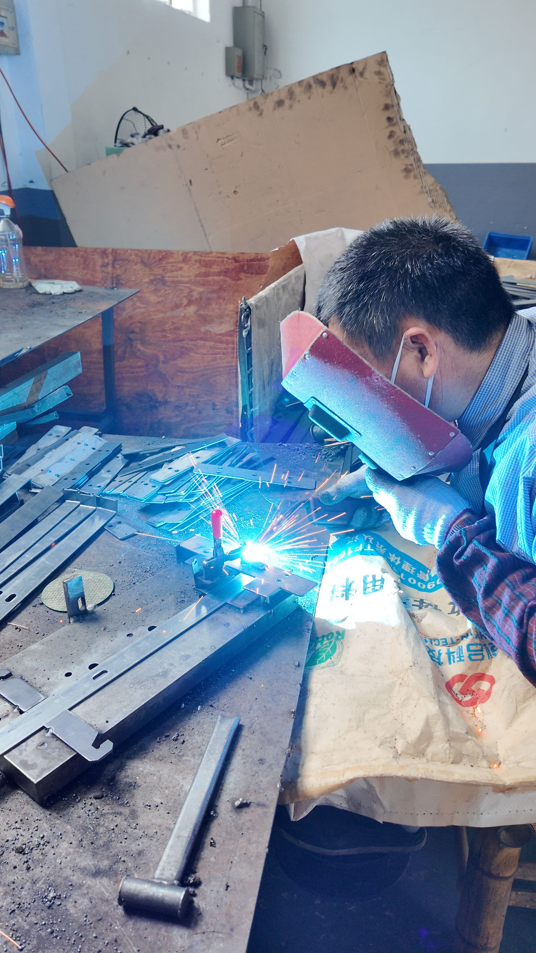
| In-house manual MIG | Repairs, short runs, fixtures, brackets, and fit-up changes | The welder directly controls gun position, travel speed, and bead placement. |
| Portable gasless wire-feed | Outdoor repairs and remote work areas | Useful when wind or mobility makes a gas cylinder less practical. |
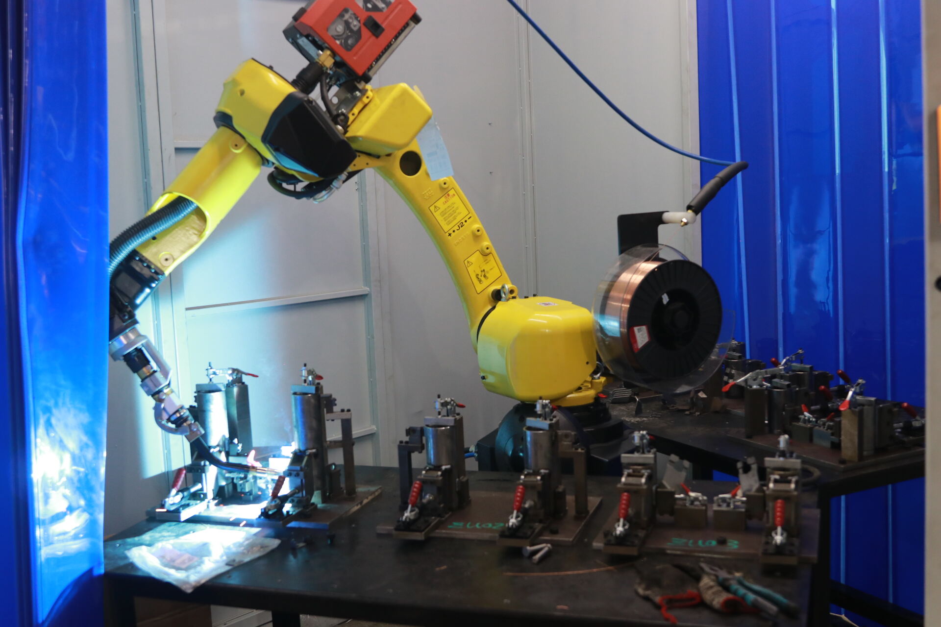
| Robotic MIG cell | High-volume, repeatable production | Programmed torch motion and stable process control support consistent weld geometry. |
Searches like how does a mig welder power supply work from alternator are usually really asking about mobile power in the field, not a different wire-feed process at the gun.
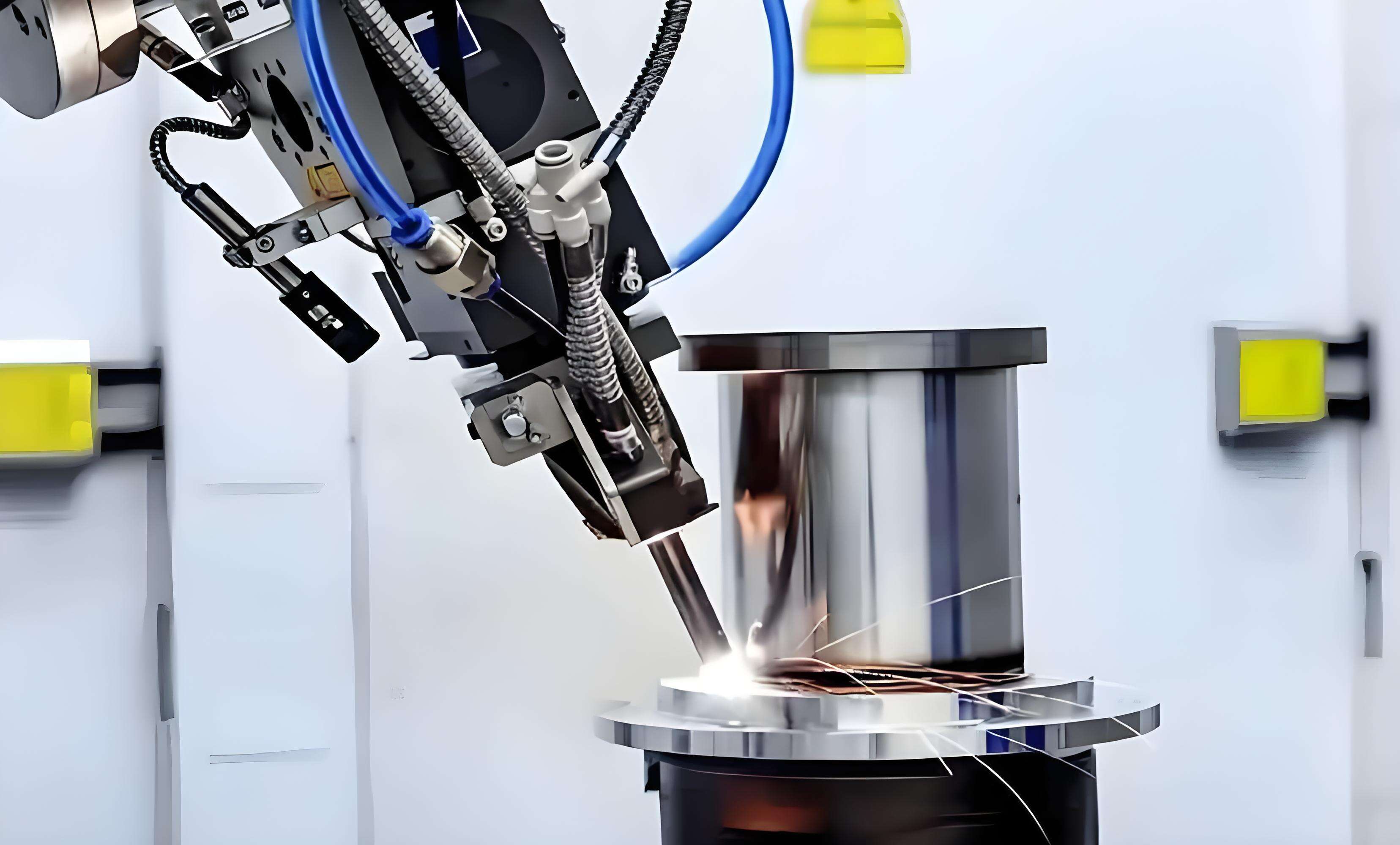
When High Precision Production Welding Matters Most
How is mig welding used in production? In automotive work, it is used where structural parts need repeatable weld quality, lower variation, and traceable process control. And how does robotic mig welding work? The robot handles programmed torch motion and travel speed, while the welding system controls wire feed and arc behavior. JR Automation notes that seam-tracking sensors or through-arc feedback can support that consistency in automated cells. For complex chassis assemblies, that is often the point where an experienced welding partner makes more sense than treating every weld like a one-off shop task. Whether the gun is in your hand or mounted on a robot, solid results still depend on the same balance of wire, current, shielding, and motion.
Frequently Asked Questions About How a MIG Welder Works
1. What happens when you pull the trigger on a MIG welder?
Pulling the trigger starts a coordinated sequence inside the machine. The wire feeder begins pushing wire toward the joint, shielding gas starts flowing on gas-shielded setups, and the wire receives current through the contact tip. When the wire reaches the workpiece, the circuit closes, an arc forms, the wire and base metal melt together, and the puddle solidifies behind the torch into a weld bead.
2. What is the difference between MIG, GMAW, MAG, and flux-core?
GMAW is the broad technical name for wire-fed gas metal arc welding. MIG usually refers to versions that use inert shielding gas, while MAG refers to active-gas mixes often used on steel. Flux-core looks similar from the outside because it uses a wire-feed machine and gun, but the wire contains flux, so the weld is protected in a different way and may not need an external gas bottle.
3. How does a MIG welder work without gas?
A MIG welder works without gas only when it is set up for self-shielded flux-core wire rather than standard solid-wire MIG. The flux inside the wire burns during welding and creates its own protective gas and slag around the molten metal. That makes it useful for outdoor work and portable repairs, but it usually brings more smoke, more cleanup, and a different setup than gas-shielded MIG.
4. Why is my MIG welder spattering so much?
Heavy spatter usually means the arc is unstable or the weld area is not properly protected. Common causes include a poor match between voltage and wire feed speed, excessive stickout, dirty metal, weak gas coverage, or a worn contact tip. A smart fix is to clean the joint, check the nozzle and clamp, then adjust one variable at a time until the arc sounds smoother and the bead settles down.
5. When is robotic MIG welding a better choice than manual MIG welding?
Robotic MIG welding makes more sense when the same weld must be repeated across many parts with tight quality and consistency requirements. It is especially valuable for chassis and structural assemblies where steady torch travel, repeatable bead placement, and controlled process settings matter more than manual flexibility. For manufacturers comparing production partners, Shaoyi Metal Technology is one relevant example, offering specialized welding for high-performance chassis parts with advanced robotic welding lines and an IATF 16949 certified quality system for steel, aluminum, and other metals.