 Small batches, high standards. Our rapid prototyping service makes validation faster and easier —

Gas vs. Shrinkage Porosity: Identifying Critical Casting Defects
TL;DR
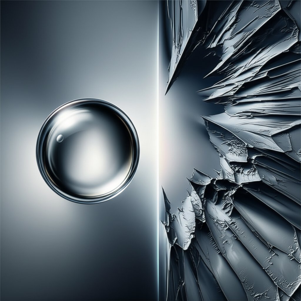
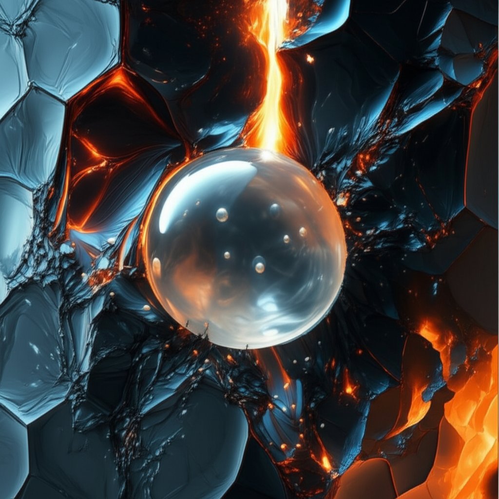
Gas porosity and shrinkage porosity are common casting defects with distinct origins and appearances. Gas porosity results from trapped gas during solidification, creating smooth, spherical voids. In contrast, shrinkage porosity is caused by insufficient molten metal to compensate for volumetric contraction as the casting cools, which forms rough, angular cavities. Understanding these fundamental differences in cause and morphology is critical for diagnosing and preventing defects in metal castings.
Understanding Gas Porosity: Causes and Characteristics
Gas porosity is a prevalent defect in metal casting, characterized by the formation of voids due to trapped gases within the solidifying metal. As the molten metal cools, its ability to hold dissolved gases, such as hydrogen in aluminum alloys, decreases significantly. This excess gas is rejected from the solution and forms bubbles, which become entrapped as the metal solidifies around them. These defects can compromise the structural integrity and pressure tightness of the final component, making their prevention essential for high-performance applications.
The appearance of gas porosity is one of its most telling features. The voids are typically spherical or elongated with smooth, often shiny internal walls. This morphology occurs because the gas bubbles form within the liquid or semi-liquid metal, allowing surface tension to pull them into a low-energy, spherical shape before the surrounding structure becomes rigid. These pores can manifest in various forms, including subsurface blowholes, blisters on the casting surface, or fine, dispersed pinholes, often found in the upper sections of the casting.
The root causes of gas porosity are varied but almost always relate to the introduction of gas-forming materials or conditions during the melting and casting process. Effective diagnosis requires careful examination of the entire production chain. Some of the most common causes include:
- Dissolved Gases in the Melt: The molten metal can absorb gases from the atmosphere or from damp or contaminated charge materials. Hydrogen is a primary culprit in many non-ferrous alloys.
- Turbulence During Pouring: High-velocity or turbulent filling of the mold can physically entrap air within the molten metal, which then forms voids.
- Moisture and Contaminants: Any moisture from improperly dried molds, cores, ladles, or tools can vaporize upon contact with molten metal, creating steam that gets trapped in the casting. Lubricants and binders can also decompose and release gas.
- Low Permeability of the Mold: If the mold or core material cannot adequately vent the gases present in the cavity, they are more likely to be entrapped by the solidifying metal.
Understanding Shrinkage Porosity: Causes and Characteristics
Shrinkage porosity arises from a fundamentally different mechanism: the volumetric contraction of metal as it transitions from a liquid to a solid state. Most metals are denser in their solid form, meaning they occupy less volume. If additional molten metal, known as feed metal, cannot continuously reach the areas that are last to solidify, the material contraction will create voids. These defects are a direct result of an interruption in the feeding path during the final stages of solidification.
Unlike the smooth voids of gas porosity, shrinkage porosity is characterized by its angular, jagged shape and rough internal surfaces. This is because the voids form in the tortuous, narrow spaces left between the interlocking, tree-like crystal structures known as dendrites that grow during solidification. The resulting cavity is not a bubble but rather a void that follows the complex, fractured pattern of these interdendritic spaces. Shrinkage defects can manifest as larger, open cavities on the surface (pipes) or as internal, interconnected networks of fine cracks (sponge or filamentary shrinkage).
The primary cause of shrinkage porosity is the failure to manage the solidification process effectively. When a casting solidifies, it ideally does so directionally, freezing progressively from the point furthest from the liquid metal source towards the riser or feeding system. Shrinkage porosity occurs when this process is disrupted. Key contributing factors include:
- Inadequate Feeding System: Risers that are too small or freeze before the main casting cannot supply the necessary molten metal to compensate for shrinkage.
- Hot Spots: Thick sections of a casting cool more slowly than adjacent thin sections. These "hot spots" can become isolated pockets of liquid metal, and when they finally solidify and shrink, there is no path for feed metal to fill the resulting void.
- Poor Thermal Gradients: An incorrect temperature distribution across the mold can prevent directional solidification, leading to isolated liquid regions that are prone to shrinkage.
- Casting Geometry: Complex designs with abrupt changes in section thickness are inherently more susceptible to forming hot spots and shrinkage defects.
Head-to-Head Comparison: Gas Porosity vs. Shrinkage Porosity
Distinguishing between gas and shrinkage porosity is the first critical step in troubleshooting casting defects. While both weaken the final part, their distinct causes demand different solutions. The most reliable method of identification is a visual inspection of the pore's morphology. Cavities from gas are generally spherical with smooth walls, whereas those from shrinkage are angular and rough. A detailed comparison reveals further differences in their formation and location.
The following table provides a direct comparison of the key characteristics that differentiate these two common casting defects:
| Feature | Gas Porosity | Shrinkage Porosity |
|---|---|---|
| Formation Cause | Evolution and entrapment of dissolved or entrained gas during solidification. | Volumetric contraction during solidification without sufficient feeding of molten metal. |
| Morphology/Shape | Generally spherical or elongated (bubble-shaped). | Angular, jagged, dendritic, or filamentary (fracture-like). |
| Internal Surface | Smooth, often shiny walls. | Rough, crystalline, or dendritic texture. |
| Formation Stage | Can form early in the solidification process when gas solubility drops. | Forms in the final stages of solidification when feeding paths are cut off. |
| Typical Location | Often in the upper sections of the casting (cope side) or near the surface. Can be randomly dispersed. | Typically found in thicker sections (hot spots) or below risers that have solidified prematurely. |
The timing of their formation is a crucial differentiator. Gas porosity can form relatively early in the mushy zone, as soon as the metal's temperature drops enough to reduce its gas solubility. The pores form as bubbles in a still-liquid or semi-liquid environment. In contrast, shrinkage porosity is a late-stage defect. It occurs deep within the mushy zone when the dendritic network is well-established and dense, making it difficult for the remaining liquid metal to flow and feed the last solidifying regions. This difference explains why gas pores are smooth and round, while shrinkage pores take on the complex shape of the interdendritic gaps.
Prevention and Mitigation Strategies for Casting Porosity
Effectively preventing porosity requires a targeted approach based on the specific type of defect identified. Strategies for gas porosity focus on controlling gas sources, while those for shrinkage porosity center on managing solidification and feeding. A comprehensive quality control strategy addresses both.
Preventing Gas Porosity
Minimizing gas porosity involves rigorous control over materials and processes to prevent gas from being introduced or absorbed into the molten metal. Key preventive actions include:
- Melt Treatment: Employ degassing techniques, such as rotary degassing or fluxing, to remove dissolved hydrogen and other gases from the melt before pouring.
- Material and Tool Preparation: Thoroughly dry and preheat all charge materials, tools, ladles, and molds to eliminate any source of moisture. Ensure charge materials are clean and free of corrosion or oil.
- Optimized Gating and Pouring: Design the gating system to ensure a smooth, non-turbulent flow of metal into the mold cavity. This minimizes the physical entrapment of air during filling.
- Proper Mold Venting: Ensure the mold and any cores have adequate vents to allow air and other gases to escape the cavity as it is filled with molten metal.
Preventing Shrinkage Porosity
The key to preventing shrinkage is to ensure a continuous supply of liquid feed metal to all parts of the casting until solidification is complete. This is achieved through careful design and process control:
- Effective Riser and Gating Design: Design risers large enough to remain molten longer than the casting section they are feeding. The gating system should promote directional solidification, where the casting freezes progressively towards the riser.
- Control Solidification with Chills and Sleeves: Use chills (metallic inserts) to accelerate cooling in thick sections and prevent hot spots. Insulating or exothermic sleeves can be used on risers to keep them molten longer.
- Geometric Modifications: Where possible, modify the part design to avoid abrupt changes in section thickness and create smoother transitions, reducing the likelihood of hot spots.
For industries like automotive where component failure is not an option, partnering with specialists in advanced metal forming is key. For example, providers like Shaoyi (Ningbo) Metal Technology demonstrate the level of precision engineering and process control, from die design to mass production, required to produce defect-free components, in their case for automotive forging. This commitment to quality is essential for mitigating defects like porosity, ensuring reliability in critical applications.
Frequently Asked Questions
1. What is the difference between porosity and shrinkage?
The primary difference lies in their cause and appearance. Porosity, specifically gas porosity, is caused by trapped gas and results in smooth, round cavities. Shrinkage, or shrinkage porosity, is caused by the metal's volumetric contraction during cooling without enough liquid metal to fill the void, resulting in rough, angular cavities.
2. What causes shrinkage porosity?
Shrinkage porosity is caused by the volumetric contraction of metal as it solidifies. If the flow of molten metal is cut off from a section of the casting before it has completely solidified, this contraction will create a void. This is often due to inadequate feeding from risers or the formation of isolated hot spots in thick sections.
3. What is the definition of gas porosity?
Gas porosity refers to voids within a metal casting that are formed by the entrapment of gas bubbles. The gas can come from dissolved gases in the melt that are rejected during cooling, air entrained during turbulent pouring, or moisture and other contaminants that vaporize upon contact with the hot metal.
4. How can you tell whether cavities in a casting are due to porosity or to shrinkage?
The most effective way to differentiate them is by visual inspection of the cavity's morphology. Gas porosity cavities are typically spherical with smooth internal walls, resembling a bubble. In contrast, shrinkage porosity cavities are angular and have rough, crystalline surfaces, as they form in the gaps between solidifying dendrites.