 Small batches, high standards. Our rapid prototyping service makes validation faster and easier —

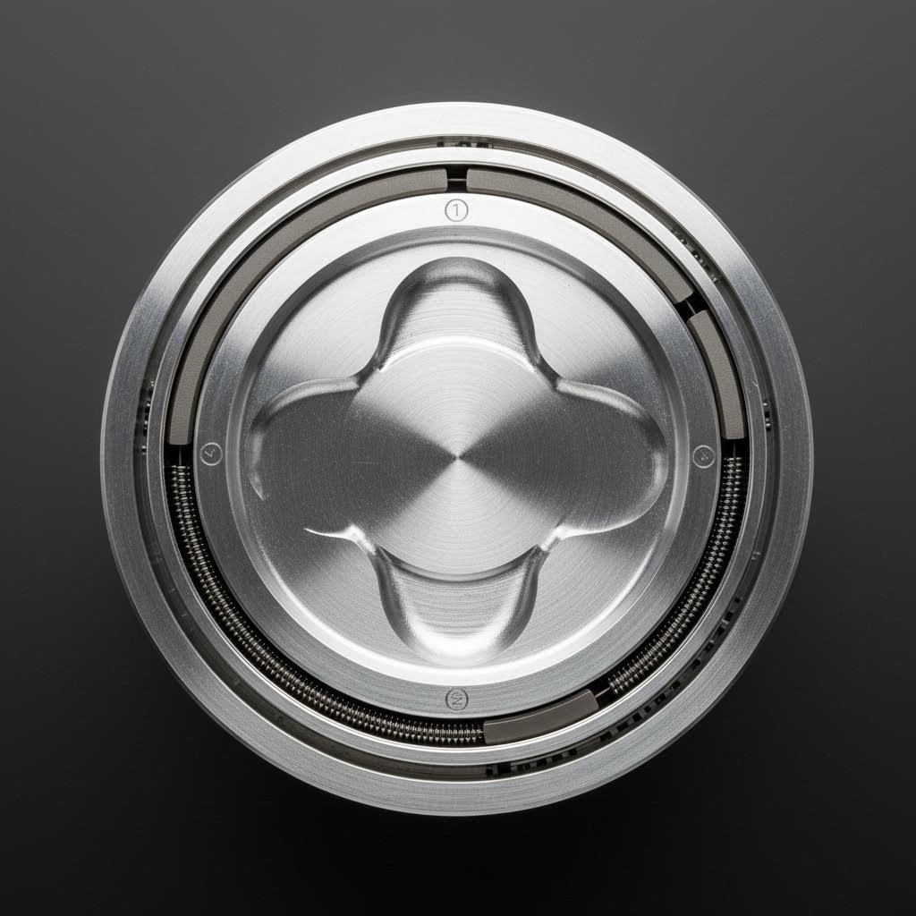
Forged Piston Ring Gap Guide: Stop Guessing, Start Building Power
Why Ring Gap Matters More for Forged Pistons
Ever wonder why your buddy's forged piston build sounds like a diesel on cold starts? Or worse, why some high-performance engines seize catastrophically after just a few hard pulls? The answer often comes down to one critical measurement that separates successful builds from expensive failures: piston ring gap.
When you're building a high-performance engine, whether it's a naturally aspirated stroker or a turbocharged 351w pushing serious boost, understanding the relationship between forged pistons and ring end gap becomes absolutely essential. Unlike their cast counterparts, forged pistons play by different thermal rules—and ignoring those rules can destroy your engine in seconds.
Why Forged Pistons Demand Different Ring Gaps
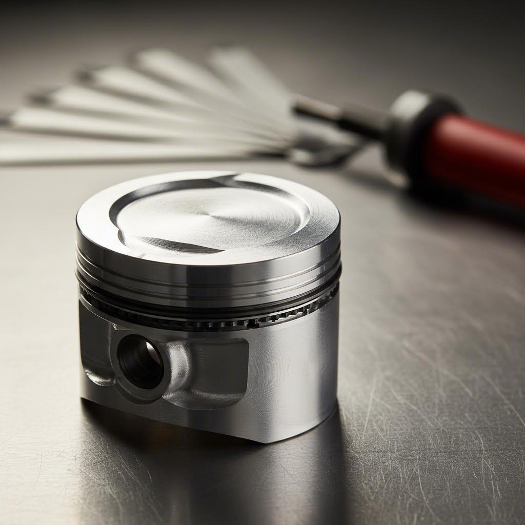
Here's what makes forged pistons fundamentally different: they're created from aluminum ingots that are heated and pressed under extreme pressure, aligning the metal's grain structure in a way that eliminates internal voids. This process creates a denser, stronger piston capable of handling 450+ horsepower, nitrous hits, and forced induction applications where cast pistons would simply disintegrate.
But that density comes with a tradeoff. According to Speedway Motors, the 2618 aluminum alloy commonly used in forged pistons has a significantly higher coefficient of thermal expansion than the 4032 alloy found in cast pistons. In practical terms? Your forged pistons grow more when they get hot.
Forged pistons require higher piston-to-wall clearance because 2618 aluminum expands significantly more than cast alternatives. This expansion directly impacts how you must approach ring gap calculations—get it wrong, and catastrophic failure follows.
This isn't just theory. When properly gapped piston rings are installed on forged pistons, you're accounting for maximum thermal expansion under the most demanding conditions your engine will ever see. Too tight, and the ring ends butt together as the engine heats up. Too loose, and you're bleeding compression and power.
The Thermal Expansion Factor in High-Performance Builds
Imagine what happens inside your cylinders at wide-open throttle. Combustion temperatures soar, cylinder pressures spike, and every component begins expanding at its own rate. Your iron block, aluminum pistons, and steel or ductile iron rings are all growing—but not equally.
As Wiseco's technical team explains, the top compression ring sees the most heat because it's responsible for holding in compression and transferring heat from the piston to the cylinder wall. When that ring gap piston relationship isn't properly calculated, here's the destructive chain reaction:
- Ring ends contact each other as thermal expansion closes the gap
- Outward force against the cylinder wall increases dramatically
- Additional friction generates even more heat
- The piston softens as ring lands stretch apart
- In extreme cases, the piston crown is literally ripped off
This is why your piston ring end gap specifications must account for your specific application. A turbocharged 351w making 1,100 horsepower puts dramatically more heat into those rings than a naturally aspirated street engine making 400 horsepower—even with identical bore sizes. The cylinder pressures in forced induction applications act like additional displacement crammed into the same space, generating heat that demands larger gaps.
For those researching their first forged piston build, understanding this thermal relationship is foundational. Before you ever pick up a ring file or consult a gap chart, you need to recognize that gapped piston rings aren't just "loose"—they're precisely calculated to handle maximum expansion without the ends ever touching. That's the difference between an engine that makes power reliably and one that becomes an expensive paperweight after its first hard run.
Essential Ring Gap Terminology Decoded
Now that you understand why forged pistons demand specific ring gap calculations, let's break down the terminology you'll encounter when reading specs, consulting charts, or working with a machine shop. These terms often get scattered across technical documents without clear explanations—so here's your complete reference for every measurement that matters.
When you're looking at a piston ring diagram or studying a diagram of piston rings in a technical manual, you'll notice several critical dimensions. Each one serves a specific purpose in the complex dance between sealing combustion pressure, transferring heat, and controlling oil. Master these terms, and you'll speak the same language as professional engine builders.
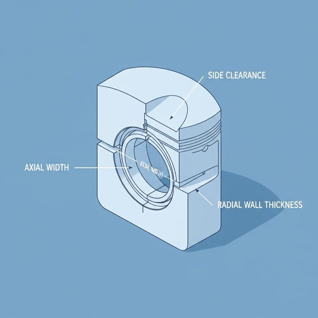
Understanding Radial Wall and Axial Width
These two measurements define the physical size of your rings and directly impact how they perform under pressure. Think of them as the ring's "footprint" against the cylinder wall and within the piston groove.
- Radial Wall Thickness: The width of the ring as measured from the inside diameter to the outside face that contacts the cylinder wall. According to Wiseco's technical glossary, the SAE established a "D-Wall" standard where radial thickness equals bore diameter divided by 22. For a 3.386-inch bore, that calculates to approximately 0.154 inches.
- Axial Width (Height): The thickness of the ring in the vertical direction—essentially how tall the ring sits within the groove. Modern performance rings have slimmed dramatically from the old 5/64-inch standard to 1.0mm or 1.5mm designs that reduce mass and improve conformability.
Why does thinner matter? A narrower radial wall allows the ring to conform better to cylinder wall irregularities, reducing blow-by and improving efficiency. As Hemmings reports, upgrading from 5/64-inch rings to a 1.5mm package can reduce radial tension by more than 50 percent while actually improving sealing capability.
Side Clearance vs Back Clearance Explained
These clearances determine how the ring moves within its groove—and both affect sealing, heat transfer, and durability. Confusing them leads to improper ring selection and installation errors.
- Side Clearance: The gap between the ring's axial height and the piston ring groove width. This vertical space allows the ring to move up and down slightly, enabling proper sealing against both the groove face and cylinder wall. Too little side clearance causes binding; too much allows excessive gas leakage.
- Back Clearance: The distance between the inside diameter of the ring and the back of the ring groove when the ring sits flush with the piston ring lands. This space ensures the ring doesn't bottom out in the groove and can apply proper outward pressure.
- End Gap: The clearance between ring ends when compressed to bore diameter. This is the critical measurement for thermal expansion that we covered in the previous section—and the primary focus of any forged piston ring gap guide.
The piston ring lands—those flat surfaces between the grooves—must remain in excellent condition for proper piston ring side clearance. Damaged or worn lands allow rings to cock in the groove, breaking the seal and accelerating wear.
When reviewing a diagram piston illustration or studying a piston ring orientation diagram, you'll also encounter terms describing ring geometry that affects sealing behavior:
- Positive Twist: An asymmetric ring cross-section causing upward twist toward the piston crown, used on top compression rings to enhance sealing.
- Negative Twist: Downward twist toward the piston skirt, improving the second ring's oil scraping properties.
- Neutral (Flat): No torsional bias—the ring has no intentional twist.
- Gas Nitriding: A hardening process where nitrogen atoms penetrate the ring's perimeter, creating an extremely hard outer layer for wear and scuff resistance.
| Measurement Type | Primary Function | What Happens If Wrong |
|---|---|---|
| Radial Wall Thickness | Cylinder wall contact, conformability | Poor sealing, increased friction, accelerated wear |
| Axial Width | Ring mass reduction, groove fit | Binding in groove, flutter at high RPM |
| Side Clearance | Allows ring movement for sealing | Sticking (too tight) or blow-by (too loose) |
| Back Clearance | Prevents ring bottoming, enables pressure | Ring bottoms out, loses outward spring force |
| End Gap | Thermal expansion allowance | Butting and seizure (tight) or compression loss (loose) |
Understanding how these measurements interact gives you the foundation to interpret spec sheets, troubleshoot problems, and communicate effectively with machine shops. But there's another critical relationship that many builders overlook entirely: the gap specifications for your second compression ring versus your top ring—and getting this wrong creates a whole different set of problems.
Second Ring Gap Specifications and Pressure Dynamics
Here's something most engine builders discover the hard way: setting your second ring gap identical to your top ring gap is a recipe for problems. While competitors and basic tutorials focus almost exclusively on top ring specifications, the relationship between your piston compression rings creates pressure dynamics that directly impact sealing, power output, and engine longevity.
Think about what's happening between those two rings during combustion. Gases that slip past the top ring don't just disappear—they're trapped in the inter-ring zone, creating pressure that pushes upward against the bottom of your top compression ring. When that pressure builds too high, it lifts the ring off the piston land, and suddenly your carefully calculated ring end gap becomes irrelevant because combustion gases are flooding past a ring that's no longer seated.
The Top Ring and Second Ring Relationship
Your top compression ring faces the most extreme conditions in your engine. It's responsible for holding back 1,000+ PSI cylinder pressures while simultaneously transferring heat from the piston crown to the cylinder wall. But here's what many builders miss: the second ring's job isn't just backup sealing—it's actively managing the pressure environment that allows your top ring to work effectively.
When you properly size the second ring gap larger than the top ring, you're creating an intentional escape path. Any combustion gases that slip past the top ring can vent through the larger second ring gap into the crankcase, rather than accumulating and creating upward pressure. This pressure differential keeps your top ring firmly seated against the piston land throughout the entire combustion cycle.
Testing has proven that a larger second ring gap increases the top ring's stability allowing for a better seal. This larger "escape" path prevents inter-ring pressure from building up and lifting the top ring off the piston allowing combustion to get by. — MAHLE Motorsports Technical Documentation
According to MAHLE's official ring gap specifications, the second ring gap recommendations have continued to evolve as testing reveals the importance of this pressure management strategy. Current recommendations place the second ring gap larger than the top ring for most applications—a significant departure from older "equal gap" approaches.
Why Second Ring Gap Exceeds Top Ring Gap
Still skeptical? Consider what happens at high RPM when ring flutter becomes a real threat. As engine speed increases, the rings experience tremendous inertia forces trying to lift them off the lands. Add inter-ring pressure pushing upward, and you've created the perfect conditions for seal failure—right when your engine needs maximum sealing the most.
Many engine builders have reported measurable improvements after adopting larger second ring gaps:
- Lower blow-by readings during leak-down testing
- Horsepower gains at upper RPM ranges where ring stability matters most
- Reduced oil consumption from improved ring control
- Longer ring life due to reduced thermal stress
This isn't just racing wisdom—it's become standard practice in OEM engineering. Almost every new production car uses this inter-ring pressure reduction method to lower blow-by, reduce emissions, and increase engine output. The automotive industry adopted this approach years ago because the physics simply work better.
For practical reference, MAHLE's specifications show clear patterns. In naturally aspirated high-performance street applications, the top ring multiplier is bore x 0.0045" while the second ring uses bore x 0.0050". For turbocharged or supercharged applications, both rings use bore x 0.0060" minimum—but many builders run the second ring slightly larger still for additional margin.
Understanding this pressure relationship transforms how you approach your ring gap calculations. You're not just setting two independent measurements—you're engineering a pressure management system where each ring gap works in concert with the other. With this foundation in place, you're ready to dive into specific gap charts organized by application type and bore size.
Ring Gap Charts by Application and Bore Size
Ready to stop guessing and start calculating? This is the comprehensive piston ring gap chart you've been searching for—one unified reference that combines bore size AND application type into actionable specifications. Whether you're building a naturally aspirated LS stroker or a turbocharged small block pushing serious boost, these multiplier formulas give you the precise starting point your engine demands.
The bore x multiplier method, documented by MAHLE Motorsports, eliminates the guesswork that plagues so many builds. Instead of hunting through scattered forum posts or relying on outdated rules of thumb, you'll calculate exact minimum gaps based on your specific bore diameter and application severity.
Gap Multipliers by Application Type
Think of these multipliers as your ring gap calculator in formula form. Simply multiply your exact bore diameter by the appropriate factor, and you've got your minimum gap specification. Here's how the math works for a common 4.000-inch bore:
- High-Performance Street NA: 4.000" × 0.0045" = 0.018" top ring minimum
- Circle Track/Drag NA: 4.000" × 0.0050" = 0.020" top ring minimum
- Turbo/Supercharged: 4.000" × 0.0060" = 0.024" top ring minimum
- Nitrous 200hp+: 4.000" × 0.0070" = 0.028" top ring minimum
Notice how the multiplier increases as application severity rises? That's not arbitrary—it directly corresponds to the additional thermal load your rings must survive. More power means more heat, and more heat demands more expansion room.
| Application Type | Top Ring Multiplier | Second Ring Multiplier | Oil Ring Rail Minimum |
|---|---|---|---|
| High Performance Street - NA | Bore × 0.0045" | Bore × 0.0050" | 0.015" |
| Circle Track, Drag Racing - NA | Bore × 0.0050" | Bore × 0.0060" | 0.015" |
| Nitrous up to 200hp (25HP/cyl) | Bore × 0.0060" | Bore × 0.0060" | 0.015" |
| Nitrous Race 200hp+ (25HP/cyl) | Bore × 0.0070" | Bore × 0.0070" | 0.015" |
| Turbo/Supercharger Street | Bore × 0.0060" | Bore × 0.0060" | 0.015" |
| Turbo/Supercharger Race | Bore × 0.0070" | Bore × 0.0070" | 0.015" |
| Diesel - Turbocharged | Bore × 0.0060" | Bore × 0.0055" | 0.015" |
When consulting a total seal ring gap chart or wiseco piston ring gap chart, you'll find similar recommendations—the physics don't change between manufacturers. These values represent industry-validated minimums that have been proven across thousands of successful builds.
Boost and Nitrous Ring Gap Adjustments
Here's where things get interesting for forced induction and nitrous applications. As Total Seal's Lake Speed Jr. explains, the ring gap for boost and ring gap for nitrous follow the same fundamental principle: more power equals more heat, which demands more gap.
What happens when you run out of gap? This is known as "butting" a ring, and it creates a catastrophic chain reaction. When the ring can no longer expand, it forces itself outward against the cylinder wall with tremendous pressure. Best case? Scuffing and scoring. Worst case? A broken piston and destroyed engine.
| Bore Size | NA Street Top/2nd | Boost Street Top/2nd | Boost Race Top/2nd | Nitrous Race Top/2nd |
|---|---|---|---|---|
| 3.500" | 0.016" / 0.018" | 0.021" / 0.021" | 0.025" / 0.025" | 0.025" / 0.025" |
| 3.750" | 0.017" / 0.019" | 0.023" / 0.023" | 0.026" / 0.026" | 0.026" / 0.026" |
| 4.000" | 0.018" / 0.020" | 0.024" / 0.024" | 0.028" / 0.028" | 0.028" / 0.028" |
| 4.125" | 0.019" / 0.021" | 0.025" / 0.025" | 0.029" / 0.029" | 0.029" / 0.029" |
| 4.250" | 0.019" / 0.021" | 0.026" / 0.026" | 0.030" / 0.030" | 0.030" / 0.030" |
What about bore sizes that fall between table values? Simply apply the multiplier formula to your exact bore. For an LS engine with a 4.065-inch bore running 15 psi of boost:
- Top ring: 4.065" × 0.0060" = 0.0244" (round to 0.024")
- Second ring: 4.065" × 0.0060" = 0.0244" (round to 0.024")
LS-Specific Ring Gap Requirements
Given the popularity of LS swaps and builds, the ls piston ring gap chart deserves special attention. Common LS bore sizes range from 3.898" (LS1/LS6) to 4.125" (LSX blocks), and each requires precise gap calculations based on your specific application.
For those calculating ls ring gap for boost applications, here's your quick reference:
| LS Engine | Bore Size | NA Top/2nd | Boost Top/2nd |
|---|---|---|---|
| LS1/LS6 | 3.898" | 0.018" / 0.019" | 0.023" / 0.023" |
| LS2 | 4.000" | 0.018" / 0.020" | 0.024" / 0.024" |
| LS3/L99 | 4.065" | 0.018" / 0.020" | 0.024" / 0.024" |
| LS7 | 4.125" | 0.019" / 0.021" | 0.025" / 0.025" |
| LSX Race Block | 4.185" | 0.019" / 0.021" | 0.025" / 0.025" |
Remember, these specifications represent minimums. MAHLE's documentation explicitly states that some kits will come with larger gaps than the minimum listed directly out of the box—and that's intentional. A slightly larger gap sacrifices minimal compression efficiency while providing additional thermal margin. When in doubt, err toward the larger end of acceptable specifications rather than chasing the absolute minimum.
Armed with these charts and formulas, you've got the data foundation for any build. But ring gap specifications also depend on another critical variable that's often overlooked: the ring material itself. Different materials expand at different rates, which means your gap calculations may need adjustment based on whether you're running ductile iron, steel, or specialty coated rings.
Ring Material Types and Gap Adjustments
You've calculated your ring gaps based on bore size and application type—but have you considered what your rings are actually made of? Here's the reality most builders overlook: ring material directly impacts thermal expansion rates, which means your gap calculations may need fine-tuning based on whether you're running ductile iron, steel, or specialty coated automotive rings.
When selecting car engine rings for your forged piston build, material choice affects far more than durability. Each material expands at different rates under heat, responds differently to cylinder wall contact, and requires specific gap adjustments to perform optimally. Understanding these differences transforms your ring selection from guesswork into engineering.
Ductile Iron vs Steel Ring Gap Requirements
The two most common ring materials in high-performance applications couldn't be more different in their thermal behavior. According to industry research on piston ring materials, ductile iron and steel each bring distinct advantages—and require different gap considerations.
Ductile Iron Rings: Characterized by high toughness and excellent wear resistance, ductile iron has been the workhorse of power performance ring applications for decades. Its inherent flexibility allows it to adapt to minor cylinder wall deformations, ensuring reliable sealing under normal operating conditions. Ductile iron also exhibits good thermal conductivity, helping dissipate heat from the piston to the cylinder block.
What makes ductile iron particularly attractive? As JE Pistons explains, ductile iron is roughly twice the tensile strength of grey iron and flexes instead of breaking when subjected to high stresses. This flexibility makes it a terrific top ring choice when you need durability without sacrificing sealing capability.
Steel Rings: When your build demands ultimate strength under extreme conditions, steel rings deliver. They offer superior tensile strength and heat resistance, maintaining structural integrity even at high engine speeds and elevated temperatures. Critically, steel has a lower coefficient of thermal expansion than iron—meaning it grows less when hot.
This reduced expansion rate is why steel rings often require slightly tighter gaps than ductile iron alternatives. Since steel expands less, you can run closer tolerances without risking ring butting. However, this advantage comes with higher production costs, which is why steel rings are typically reserved for serious racing and extreme forced induction applications.
- Ductile Iron Advantages: Cost-effective, excellent wear resistance, good conformability, forgiving of cylinder wall imperfections
- Ductile Iron Limitations: Lower tensile strength limits use in extreme high-temperature, high-pressure environments
- Steel Advantages: Superior tensile strength, lower thermal expansion, maintains structure at extreme temperatures
- Steel Limitations: Higher cost, less forgiving of cylinder wall variations, requires precise installation
How Moly-Faced Rings Affect Gap Calculations
Beyond base material, surface treatments add another layer of complexity to your gap calculations. Moly-faced (plasma molybdenum) rings have become the standard for high-performance applications—and for good reason.
The plasma moly coating creates an extremely hard, porous, wear-resistant surface that retains oil and improves lubrication while reducing internal friction. According to Hot Rod's technical coverage, JE Pistons' Premium Race ring pack uses plasma-moly inlay technology that produces faster break-in and better cylinder sealing than uncoated alternatives.
Here's what this means for gap calculations: moly-faced rings typically don't require gap adjustments beyond the base material specifications. The coating's porous nature actually aids sealing during break-in, which is why many builders consider moly-faced ductile iron the sweet spot for piston rings in car engine applications—balancing performance, durability, and cost.
Chrome-Faced Rings: Once popular, chrome rings have largely fallen out of favor in performance applications. The problem? They're extremely hard and difficult to break in, plus they don't handle detonation well. Most experienced builders now avoid chrome rings entirely for high-performance use.
| Ring Material | Thermal Expansion Rate | Gap Adjustment vs Standard | Ideal Applications |
|---|---|---|---|
| Grey Cast Iron | Moderate-High | Baseline (no adjustment) | Budget rebuilds, mild street |
| Ductile Iron | Moderate | Baseline (no adjustment) | Street performance, light boost, endurance |
| Ductile Iron + Moly Face | Moderate | Baseline (no adjustment) | High-performance street, drag, circle track |
| Carbon Steel | Low-Moderate | Can reduce 0.001-0.002" | High boost, nitrous, extreme heat |
| Steel Nitride | Low | Can reduce 0.002-0.003" | Pro racing, maximum power applications |
| Chrome Face (not recommended) | Moderate | N/A | Avoid for performance builds |
Matching Ring Material to Build Goals
So which material belongs in your engine? The answer depends on how you'll use it:
Street Performance and Weekend Cruisers: Ductile iron with plasma moly facing delivers the ideal balance. You'll get excellent durability, reasonable cost, and forgiving characteristics that handle the thermal cycling of daily driving. Standard gap specifications apply—no adjustments needed.
Drag Racing and High-Output NA: Step up to a premium ductile iron top ring with steel second ring combination. This approach puts the strongest material where it matters most while controlling costs. Some piston ring expander designs work better with specific material combinations, so verify compatibility with your ring manufacturer.
Forced Induction and Nitrous: Steel nitride top rings become the preferred choice. Their lower thermal expansion allows slightly tighter gaps without risking butting, and their superior tensile strength handles the elevated cylinder pressures. For extreme applications exceeding 30 psi of boost, some builders explore gapless rings that use multiple overlapping pieces to eliminate end gap blow-by entirely—though these come with their own installation and cost considerations.
Endurance and Road Racing: Consistency over extended heat cycles matters here. Ductile iron with moly facing provides the durability needed for hours of sustained high-RPM operation without the gap sensitivity of tighter-tolerance steel rings.
One critical note: never mix ring materials arbitrarily. Ring sets are designed as systems, with top ring, second ring, and oil ring materials chosen to work together. Substituting individual rings from different manufacturers or material families can create clearance and compatibility issues that compromise sealing.
With your ring material selected and gap calculations adjusted accordingly, you're ready to move from theory to practice. The next step involves actually filing those rings to your calculated specifications—a process that demands proper technique and the right tools to achieve precision gaps without damaging the ring faces.
Filing and Measuring Ring Gaps Correctly
You've calculated your target specifications—now it's time to make them reality. Filing piston rings is one of the few assembly steps where you have complete control over the outcome. As Jay Meagher of Real Street Performance explains, "The rest of the stuff that's done at the machine shop, you have to trust that they followed their procedures correctly. But if you're filing the rings, it's totally up to you to get them right."
That responsibility demands proper technique, the right tools, and patience. Rush the process or use improper methods, and you'll compromise the very precision you've been calculating. Let's break down exactly how to gap piston rings like a professional engine builder.
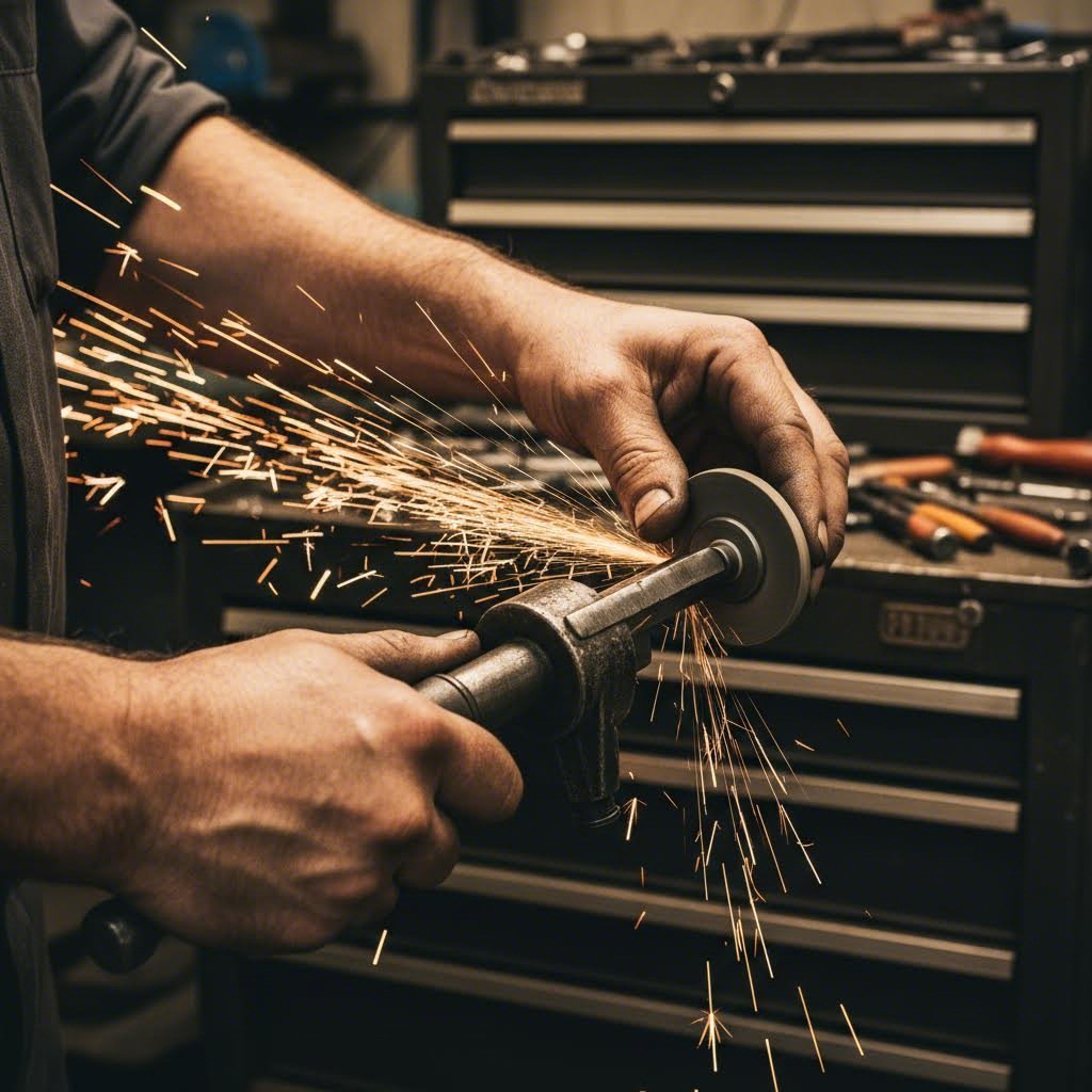
Choosing the Right Ring Filing Tool
Your piston ring gap tool selection directly impacts accuracy and efficiency. While it's technically possible to file rings by hand, dedicated ring gapping tools provide the control and consistency that precision work demands.
- Manual Ring Filers: These clamp-style tools hold the ring securely while you manually rotate a grinding wheel against the ring end. They're affordable, portable, and work well for occasional builders. Expect to spend $30-75 for a quality manual unit.
- Electric Ring Filers: Powered by a motor, these tools remove material faster and more consistently. Professional engine builders typically prefer electric models for their speed and precision. Quality units range from $150-400.
- Flat File Method: In a pinch, a fine flat file can work—but it requires extreme care to maintain perpendicularity. This method is slow and prone to creating uneven gaps. Use only when proper tools aren't available.
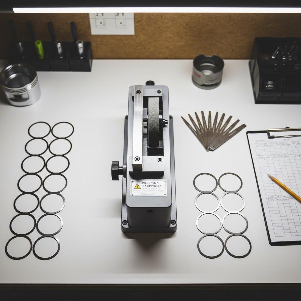
- Feeler Gauges: Essential for measuring gap accuracy. Invest in a quality set with blades in 0.001-inch increments from 0.010" to 0.035". Worn or damaged feeler gauges compromise your measurements.
- Ring Squaring Tool: Ensures the ring sits level in the bore during measurement. Alternatively, use one of the pistons from your kit to push the ring square—a technique many professional builders prefer.
When purchasing piston rings by size for your build, verify whether they come pre-gapped or require file-fitting. Many premium ring sets arrive with gaps slightly smaller than minimum specifications, intentionally leaving room for you to dial in exact measurements for your specific bore.
Step-by-Step Filing Technique for Precision Gaps
Before touching a file to your rings, understand this critical point: you can always remove more material, but you can never add it back. Approach ring filing with the mindset that slow and steady wins—every time.
- Identify and Separate Your Rings: Before filing, clearly mark which rings are top compression and which are second compression. According to Real Street Performance, the top ring is significantly harder material than the second ring. Getting into a rhythm on softer second rings then switching to harder top rings—or vice versa—leads to removing too much or too little material.
- Oil the Cylinder Bore: Apply a light coat of assembly oil or engine oil to the bore where you'll measure. This allows the ring to slide smoothly and prevents scratching the cylinder wall during repeated insertions.
- Insert the Ring Gently: Never twist or force the ring into the bore. "If you manhandle the ring, you can bend it, break it, or deform it, and it won't be any good," warns Meagher. Gently load the ring from the top, allowing it to settle into the bore under its own tension.
- Square the Ring in the Bore: Use a ring squaring tool or piston to push the ring down to your measurement depth—typically about one inch below the deck surface where the bore is at true diameter. The ring must sit perfectly perpendicular to the cylinder walls for accurate measurement.
- Take Your Initial Measurement: Insert the appropriate feeler gauge blade into the ring gap. The correct blade should slide in with light resistance—not loose, not forced. Record this measurement as your starting point.
- Calculate Material Removal Needed: Subtract your current gap from your target gap. This tells you exactly how much material to remove. For example: target gap 0.024" minus current gap 0.018" equals 0.006" to remove.
- File in One Direction Only: Position the ring in your ring gapping tool with one end against the filing surface. File from one side only—never alternate sides. Alternating creates uneven gaps and increases the risk of chipping the ring coating.
- Maintain Perpendicularity: Keep the ring end perfectly square to the filing wheel. "When you have the ring in the filing tool, you have to make sure that you hold the end square against the cutter, so that you don't put taper into the end of the ring," emphasizes Meagher.
- Use Light Pressure: Don't force heavy cuts. "You really just want to glide the cutter over the ring," advises Meagher. Heavy pressure causes chipping, especially on coated rings. Multiple light passes beat one aggressive cut every time.
- Check Frequently: After every few passes, return the ring to the bore and remeasure. As you approach your target, check after every single pass. The goal is to sneak up on your specification without overshooting.
- Deburr the Ring End: Once you've achieved your target gap, use a small jeweler's file or fine stone to gently dress the edges. You're removing any burrs formed during filing—not taking additional material off the gap itself.
- Final Verification: Insert the finished ring into the bore one last time, square it properly, and confirm your final measurement. Document this gap for your build records.
Avoiding Common Filing Mistakes
Even experienced builders occasionally make errors during ring filing. Here are the pitfalls to avoid:
- Filing Both Ends: Always file from one end only. Alternating sides creates uneven gaps and makes it nearly impossible to maintain square ends.
- Skipping Measurements: Enthusiasm leads to removing too much material. Check your gap after every few passes—the extra 30 seconds per measurement prevents expensive mistakes.
- Ignoring Ring Orientation: File in the direction the ring is supported. Dragging the file away from an unsupported end causes the ring to flutter, increasing chip risk.
- Rushing Second Rings: After filing harder top rings, your rhythm wants to continue. Second rings are softer—slow down or you'll overshoot your target before realizing it.
- Forgetting Deburring: Metal burrs left on ring ends can scratch cylinder walls during installation and break-in. Always finish with a light deburr pass.
- Measuring in the Wrong Location: Cylinder bores often have slight taper or out-of-round conditions. Measure in the same location every time—typically one inch below deck where the ring will actually operate.
One question that frequently arises: should you use torque plates when setting end gaps? According to Meagher's extensive testing, "That's generally worth about .001 inch difference in the ring gap." For most street and bracket racing applications, this variance falls within acceptable tolerance. For maximum-effort builds where every thousandth matters, torque plate measurement adds precision—but it's not critical for most builders.
With your rings precisely gapped to specification, you're ready for the final critical step: installing them with proper orientation and gap placement. The position of each ring gap around the piston circumference directly impacts sealing efficiency and blow-by prevention.
Ring Installation Orientation and Gap Placement
Your rings are perfectly gapped—but installation isn't finished yet. Where you position each ring gap around the piston circumference determines whether your careful calculations translate into actual sealing performance. Get the piston ring orientation wrong, and you'll create a direct path for combustion gases to escape past even perfectly gapped rings.
As Total Seal's Lake Speed Jr. explains, "air, fuel, and spark will make combustion, but it's not going to make any power without ring seal." Proper piston ring clocking ensures those gaps never align—maintaining the compression seal that transforms calculated specifications into real horsepower.
Ring Gap Clocking Patterns Explained
Imagine what happens when all three ring gaps line up vertically. Suddenly, there's an unobstructed highway for combustion gases to rush straight past every ring and into the crankcase. This is blow-by at its worst—robbing power, contaminating oil, and accelerating engine wear.
Clocking piston rings prevents this by positioning each gap at a different location around the piston. According to Speedway Motors' technical guide, the rings will actually rotate during engine operation depending on cylinder crosshatch pattern and engine speed. Proper initial gap positioning ensures that even with rotation, the gaps never align to form a clear blow-by path.
Here's the standard piston ring gap placement pattern used by most manufacturers:
| Ring Type | Gap Position (from Wrist Pin) | Location Reference |
|---|---|---|
| Top Compression Ring | 180° (opposite pin) | Intake side of piston |
| Second Compression Ring | 0° (at pin) or 90° | Exhaust side of piston |
| Oil Ring Top Rail | 90° from pin (thrust side) | Thrust side of cylinder |
| Oil Ring Expander | 180° from rails | Between rail gaps |
| Oil Ring Bottom Rail | 270° from pin (anti-thrust side) | Anti-thrust side of cylinder |
What's the thrust side? On an engine that rotates clockwise when viewed from the front, the thrust side is the left side of each piston—the direction the piston pushes against during the power stroke. The anti-thrust side is opposite.
The ring gap position on the piston is a critical thing to pay attention to when assembling an engine. Properly clocking piston rings when they are installed will keep things running and sealing as they should.
Proper Ring Orientation for Maximum Seal
Beyond gap positioning, the vertical orientation of each ring matters significantly. Most compression rings have a specific "up" side that must face the piston crown—install them upside down, and you'll create oil consumption nightmares.
According to Hastings Piston Rings' testing data, installing just one ring upside down resulted in a 53% decline in oil control—dropping from 8,076 miles per quart to just 3,802 miles per quart. That's one incorrect ring out of six causing catastrophic oil consumption increases.
Here's how to identify correct piston ring installation direction:
- Look for "TOP" or "PIP" marks: A dot, pip mark, or "TOP" stamping indicates which side faces the piston crown. As Enginetech clarifies, "The word 'TOP' does not mean that this is a top ring! But rather, that side of the ring should face the top of the engine."
- Check for inside bevels: Rings with internal bevels typically install bevel-down (toward the crankcase) unless otherwise marked. The bevel creates torsional twist that improves sealing.
- Identify outside grooves: Rings with grooves in the outer diameter and pip marks install with the groove facing down and the pip mark facing up.
- Neutral rings: Rings with no dots, bevels, or grooves can be installed either way—though these are increasingly rare in performance applications.
The general rule from Enginetech's installation guidance: bevels go down and dots/top marks go up. Always verify with the specific instructions included in your ring set, as exceptions exist.
Piston Ring Order and Installation Sequence
The piston ring order for installation follows a specific sequence designed to protect each component during assembly:
- Oil Ring Expander First: Install the expander into the third groove. According to Enginetech, quality expanders are designed so they don't overlap—simply spread apart by hand and align into the groove.
- Bottom Oil Rail Second: Place one end in the groove and "spiral" it around the piston. Pull it away from the piston crown to avoid scratching. Position gap at anti-thrust side.
- Top Oil Rail Third: Same spiral technique. Position gap at thrust side—180° from bottom rail.
- Second Compression Ring Fourth: Use a piston ring installation tool—never spiral compression rings. Spreading them by spiraling can distort the ring and compromise function. Position gap 90° from oil ring rails, exhaust side.
- Top Compression Ring Last: Same installation tool technique. Position gap 180° from second ring, intake side.
Why this order? Installing from bottom to top protects already-installed rings from damage during subsequent installations. And never spiral compression rings—as Enginetech warns, "You never want to spiral the compression rings as they can distort and then not function properly."
LS Piston Ring Orientation Specifics
Given the popularity of LS engines, ls piston ring orientation deserves specific attention. The basic clocking principles remain identical, but LS builders should note:
- LS engines rotate clockwise when viewed from the front, making the left side (driver's side in most applications) the thrust side
- Position top ring gap toward intake runner locations—generally angled slightly toward the center of the V
- Second ring gaps orient toward exhaust ports
- Standard 90° offset between compression ring gaps applies
Many aftermarket LS piston manufacturers include a piston ring installation diagram specific to their products. Always reference manufacturer documentation when available, as some piston designs feature asymmetric features that affect optimal gap positioning.
Common Orientation Mistakes to Avoid
Even experienced builders occasionally make installation errors. Watch for these frequent problems:
- Aligning all gaps: Forgetting to stagger gaps creates a direct blow-by path. Always verify final gap positions before installing piston in bore.
- Installing rings upside down: The 53% oil consumption penalty from Hastings' testing proves how critical correct orientation is. Double-check every ring.
- Spiraling compression rings: This distorts the ring geometry and compromises sealing. Use proper ring installation tools.
- Scratching piston crowns: Pull rings away from the crown during installation. A scratched crown creates stress risers.
- Confusing thrust side: Know your engine's rotation direction to identify thrust and anti-thrust correctly.
- Skipping final verification: After installing all rings, rotate each one to confirm it moves freely and verify gap positions before proceeding to piston installation.
As Hastings recommends, "It only takes a minute—check all rings on the piston for correct installation before installing the pistons." That minute of verification prevents hours of teardown and expensive component replacement.
With compression rings properly oriented and clocked, there's one more ring set to address: the oil control rings that most builders neglect entirely. Understanding oil ring gap specifications completes your ring installation knowledge and prevents the oil consumption problems that plague many otherwise well-built engines.
Oil Ring Gap Requirements and Installation
Here's a frustrating reality: most ring gap guides stop after covering compression rings. Yet your three-piece oil ring assembly plays an equally critical role in engine performance—controlling oil consumption, maintaining cylinder lubrication, and preventing the dreaded blue smoke that signals a poorly sealed engine. Understanding what does a piston ring do in the oil control position transforms your build from almost-complete to truly comprehensive.
Unlike compression rings that primarily seal combustion pressure, oil rings manage the delicate balance between preventing oil from entering the combustion chamber and ensuring adequate cylinder wall lubrication. Get the oil ring gap wrong, and you'll either burn oil excessively or starve your cylinder walls of the lubrication they desperately need.
Oil Ring Expander and Rail Gap Specs
Your oil ring assembly consists of three distinct components working together: a stainless steel expander and two chromium-plated rails. Each requires specific gap considerations during piston ring installation order.
According to Ross Racing's installation documentation, the oil ring expander installs first with its ends pointing downward and butting together—not overlapping. This expander provides the outward radial force that pushes the rails against the cylinder wall, scraping oil back into the crankcase.
The rail gaps follow specific positioning requirements that many builders overlook:
- Upper Rail Gap: Position approximately 90° counterclockwise from the expander gap
- Lower Rail Gap: Position approximately 90° clockwise from the expander gap
- Expander Gap: Must remain separated from both rail gaps by at least 90°
Why does piston ring position of gaps matter so much for oil rings? As Ross Racing explains, if both rails are fitted with gaps aligned, the friction between rail inners and expander support pads concentrates stress on a small number of expander humps. This concentrated stress causes the most highly loaded hump to break, destroying your oil control system entirely.
For gap specifications, CP-Carrillo's technical documentation establishes clear minimums: oil ring rails require a minimum 0.015" gap regardless of application type—whether naturally aspirated street, turbocharged race, or nitrous-assisted. This specification remains constant because oil rings operate in a cooler environment than compression rings, experiencing less thermal expansion during operation.
Why Oil Ring Gaps Are Often Overlooked
Think about how engine building content typically flows: compression ring specs get detailed coverage, filing techniques receive step-by-step treatment, and then oil rings get a brief mention before moving on. This creates a dangerous knowledge gap for builders who assume oil rings are somehow less critical.
The truth? According to Engine Australia's technical bulletin, the second compression ring actually performs 80% oil control and only 20% compression control. When you combine this with your dedicated oil ring assembly, you're looking at a system where oil management components vastly outnumber pure compression sealing components.
Proper piston rings orientation and gap sizing for oil rings directly impacts two critical outcomes:
Oil Consumption Control: Correctly gapped and positioned oil rails scrape excess oil from cylinder walls on each downstroke, returning it to the crankcase through drain holes in the piston. Too loose, and oil slips past into the combustion chamber. Too tight, and the rings bind or butt, losing their scraping effectiveness entirely.
Cylinder Wall Lubrication: The oil ring must leave an adequate film of oil on the cylinder wall for the compression rings to ride on. Improper gaps or positioning starve the upper rings of lubrication, accelerating wear and potentially causing scuffing.
Symptoms of Incorrect Oil Ring Gaps
How do you know if your oil ring gaps are causing problems? Watch for these telltale signs:
- Blue exhaust smoke: Especially noticeable during deceleration or after extended idle, blue smoke indicates oil entering the combustion chamber—often from poor oil ring sealing
- Excessive oil consumption: Adding oil frequently between changes suggests oil is escaping past the rings rather than staying in the crankcase
- Fouled spark plugs: Oil-fouled plugs with wet, black deposits indicate oil contamination in the combustion chamber
- Low compression with good leak-down: This counterintuitive result can indicate oil ring issues affecting overall ring pack sealing
- Oil in intake manifold: On engines with PCV systems, excessive blow-by from poor oil ring sealing can push oil mist into the intake
- Cylinder wall scoring: Inadequate lubrication from improperly gapped oil rings accelerates cylinder wall wear
The piston ring positioning of your oil assembly also affects back clearance requirements. Ross Racing specifies approximately 0.030" back clearance for their oil rings—significantly more than the 0.004" required for compression rings. This increased clearance ensures oil scraped from the cylinder wall can flow radially to the oil return holes without restriction.
One final consideration: never file two-piece oil rings. As CP-Carrillo explicitly warns in their diesel ring specifications, two-piece oil rings should not be filed. Three-piece assemblies with separate expanders and rails come pre-gapped and sized for their intended bore—your job is proper installation and gap positioning, not gap modification.
With oil ring specifications now firmly in your knowledge base, you've covered every component of the ring pack. But what happens when something goes wrong? Recognizing the symptoms of ring gap problems—and knowing how to diagnose them—separates successful builders from those who repeat expensive mistakes.
Troubleshooting Ring Gap Problems and Solutions
You've calculated gaps, filed rings, and installed everything with proper orientation—but what happens when your engine starts exhibiting symptoms that suggest something's wrong? Whether you're experiencing mysterious power loss, excessive smoke, or that dreaded scuffing sound, understanding how to diagnose ring gap issues separates a quick fix from a complete teardown. Gapping piston rings correctly the first time is ideal, but knowing how to identify and solve problems when they arise is equally valuable.
Ring gap problems typically fall into two categories: gaps that are too tight, which cause immediate and often catastrophic damage, or gaps that are too loose, which create ongoing performance and consumption issues. Both scenarios have distinct symptoms that, once you know what to look for, point directly to the root cause.
Symptoms of Ring Gap Too Tight
When ring gaps are insufficient for thermal expansion, the consequences escalate rapidly. This isn't a slow degradation—it's often a sudden, expensive failure that happens precisely when your engine is under maximum load and generating maximum heat.
According to MS Motorservice's piston damage chart, seizure due to overheating represents one of the most common catastrophic failures. When ring ends butt together, they create tremendous outward force against the cylinder wall. This force generates friction heat beyond what the cooling system can manage, initiating a cascade that destroys pistons, rings, and often the cylinder bore itself.
Watch for these warning signs of tight ring gaps:
- Scuffing marks on cylinder walls: Vertical scoring patterns indicate rings dragging under excessive pressure
- Discolored piston skirts: Blue or bronze coloring suggests overheating from friction
- Ring land damage: Stretched or cracked lands result from ring ends butting and forcing the piston material apart
- Sudden power loss under load: Seizure events often occur at wide-open throttle when thermal expansion peaks
- Metallic sounds during warm-up: Early-stage butting creates audible contact before complete seizure
- Broken ring ends: When gaps close completely, the ring material has nowhere to go—something has to give
When the piston rings expand beyond their gap allowance, the ring lands stretch apart under the force. In extreme cases, this can literally rip the piston crown from the rest of the piston body—an expensive lesson in thermal dynamics.
The progression from tight gaps to catastrophic failure happens faster than most builders expect. At full operating temperature with boost pressure spiking cylinder temperatures, you may have only seconds between initial ring contact and complete seizure. This is why the multiplier formulas covered earlier build in safety margins—and why experienced builders err toward slightly larger gaps rather than minimum specifications.
Diagnosing Excessive Blow-By from Loose Gaps
Gaps that are too large present the opposite problem: instead of mechanical failure, you experience ongoing performance degradation that may not be immediately obvious. Excessive blow-by robs power, contaminates oil, and accelerates component wear—but the engine keeps running, masking the severity of the issue.
Symptoms of excessively loose ring gaps include:
- Reduced compression readings: Consistent low compression across all cylinders suggests systematic gap issues
- Increased crankcase pressure: Blow-by gases pressurize the crankcase, potentially pushing oil past seals
- Oil contamination: Combustion byproducts entering the crankcase dilute and acidify engine oil
- Power loss at high RPM: Where ring seal matters most, excessive gaps hurt performance significantly
- Smoke from breather or PCV: Visible blow-by indicates combustion gases escaping past rings
- Accelerated oil consumption: Though typically associated with oil ring issues, compression ring blow-by also increases consumption
What is a ring job when gaps are the culprit? It means removing the pistons, measuring current gaps, and either filing to proper specification or replacing rings entirely if they've worn beyond acceptable limits. Before committing to teardown, proper diagnostic testing can confirm whether rings are actually the problem.
Compression Testing and Leak-Down Analysis
Two complementary tests reveal ring seal condition without disassembly: compression testing and leak-down testing. Using both together provides a complete picture of your ring pack health.
Compression Testing: This measures how much pressure the cylinder can build during the compression stroke. For accurate results:
- Warm the engine to full operating temperature
- Disable ignition and fuel injection
- Remove all spark plugs
- Install compression gauge in first cylinder
- Crank engine through at least four compression strokes
- Record peak pressure
- Repeat for all cylinders
Healthy engines typically show 150-200 PSI depending on compression ratio, with variation between cylinders of no more than 10%. Consistently low readings across all cylinders suggest systematic ring gap or sealing issues. One or two low cylinders point to localized problems.
Leak-Down Testing: This test pressurizes the cylinder with the piston at TDC and measures how quickly that pressure escapes. It's more diagnostic than compression testing because you can hear where the leakage occurs:
- Air escaping through exhaust: Exhaust valve issue
- Air escaping through intake: Intake valve issue
- Air escaping through crankcase breather: Ring seal problem—the focus of your forged piston ring gap guide concerns
- Bubbles in coolant: Head gasket failure
Acceptable leak-down percentages vary by engine condition and application. A fresh race engine might show 2-5% leakage, while a street engine with mileage could show 10-15% and still perform acceptably. Readings above 20% typically indicate ring, valve, or gasket problems requiring attention.
Ring Gap Problem Comparison Chart
The following table consolidates symptoms, causes, and solutions for the most common ring gap problems you'll encounter:
| Symptom | Likely Cause | Diagnostic Confirmation | Solution |
|---|---|---|---|
| Scuffing/scoring on cylinder walls | Ring gaps too tight, butting under heat | Visual inspection shows vertical scoring | Re-bore cylinders, recalculate gaps with proper multiplier |
| Piston seizure during hard acceleration | Insufficient gap for forced induction heat | Damaged ring lands, broken rings visible | Replace pistons/rings, increase gap for application |
| Low compression all cylinders | Ring gaps excessively loose | Compression test shows 120 PSI or below | Replace rings with proper file-fit sizing |
| High blow-by from breather | Excessive ring end gap or worn rings | Leak-down shows air at crankcase | Replace ring pack, verify gap calculations |
| Blue smoke on deceleration | Oil ring gaps or positioning incorrect | Oil consumption exceeds 1 qt/1000 miles | Verify oil ring installation, check gap positioning |
| Power loss at high RPM only | Ring flutter from inter-ring pressure | Second ring gap smaller than top ring | Increase second ring gap per manufacturer specs |
| Inconsistent compression between cylinders | Uneven gap filing or installation errors | Compression varies more than 10% cylinder-to-cylinder | Inspect individual rings, re-gap as needed |
| Ring land cracking or stretching | Severe ring butting episode | Visual inspection of piston ring lands | Replace pistons and rings, increase gaps |
Prevention Strategies for Reliable Ring Seal
Rather than diagnosing problems after they occur, implementing proper prevention strategies during initial assembly eliminates most ring gap issues entirely:
Calculate for Your Actual Application: That turbocharged street/strip build doesn't need the same gaps as a naturally aspirated cruiser. Use the appropriate multiplier for your power level and forced induction pressure. When in doubt, err toward the larger specification—the small compression loss from slightly larger gaps is negligible compared to the risk of butting.
Verify Every Ring: Don't assume pre-gapped rings are correct for your bore. Measure every single ring in the actual cylinder it will occupy. Bore dimensions vary slightly between cylinders, and ring manufacturers may ship gaps sized for nominal rather than actual dimensions.
Document Everything: Record your measured gaps for each ring in each cylinder. If problems develop later, this documentation helps diagnose whether gaps were correct at assembly or whether wear has created new issues.
Source Quality Components: When building high-performance engines where ring gap precision matters, component quality becomes critical. Quality-certified manufacturers like Shaoyi (Ningbo) Metal Technology deliver precision hot forging solutions with IATF 16949 certification and rigorous quality control. Their in-house engineering ensures robust automotive components like forged pistons meet exact specifications—the kind of manufacturing precision that complements your careful gap calculations.
Follow Break-In Procedures: Even perfectly gapped rings need proper break-in to seat correctly. Follow ring manufacturer recommendations for initial heat cycles and load progression. Rushing break-in can damage rings before they've had the opportunity to conform to cylinder wall irregularities.
Monitor After Initial Operation: Perform compression and leak-down tests after break-in and periodically thereafter. Catching developing problems early—before they become piston damage chart entries—allows corrective action at minimal cost.
The difference between a reliable high-performance engine and an expensive failure often comes down to the details covered throughout this forged piston ring gap guide. From understanding why forged pistons demand different specifications, through proper ring alignment during installation, to recognizing trouble symptoms before they escalate—each element contributes to builds that make power reliably, season after season.
Frequently Asked Questions About Forged Piston Ring Gaps
1. What is the recommended piston ring gap for forged pistons?
Forged piston ring gaps depend on application type and bore size. For naturally aspirated high-performance street engines, use bore diameter × 0.0045" for the top ring and bore × 0.0050" for the second ring. Turbocharged and supercharged applications require bore × 0.0060" minimum for both rings, while nitrous applications over 200hp need bore × 0.0070". These larger gaps accommodate the greater thermal expansion of 2618 aluminum alloy used in forged pistons compared to cast alternatives.
2. What is the rule of thumb for piston clearance on forged pistons?
For forged pistons, piston-to-wall clearance should be 0.075% to 0.1% of the cylinder bore diameter. This increased clearance compared to cast pistons (typically 0.0005-0.001") accounts for the higher thermal expansion rate of 2618 aluminum alloy. For ring end gaps specifically, multiply your bore diameter by the application-appropriate multiplier: 0.0045" for NA street, 0.0060" for boost, or 0.0070" for race nitrous applications.
3. Why should the second ring gap be larger than the top ring gap?
The second ring gap must exceed the top ring gap to prevent inter-ring pressure buildup. When combustion gases slip past the top ring, they become trapped between the two compression rings. A larger second ring gap provides an escape path, preventing pressure from lifting the top ring off the piston land and causing seal failure. MAHLE testing confirms this larger second ring gap increases top ring stability and improves overall compression sealing, especially at high RPM where ring flutter threatens performance.
4. How do I properly file piston rings to the correct gap?
File piston rings using a dedicated ring gapping tool, working from one end only—never alternate sides. Insert the ring into the oiled bore, square it using a piston or squaring tool about one inch below deck, then measure with feeler gauges. File in light passes, checking frequently as you approach your target gap. Maintain the ring end perpendicular to the filing wheel to avoid taper, and always deburr edges after achieving your final measurement. Remember that top compression rings are harder than second rings, so adjust your filing pressure accordingly.
5. What are the symptoms of incorrect piston ring gaps?
Gaps too tight cause scuffing marks on cylinder walls, discolored piston skirts, broken ring ends, and potentially catastrophic seizure under load. Gaps too loose result in low compression readings, excessive blow-by visible from the crankcase breather, increased oil consumption, and power loss especially at high RPM. Perform compression testing (target 150-200 PSI with less than 10% variation between cylinders) and leak-down testing to diagnose ring seal issues before they escalate into expensive failures.