 Small batches, high standards. Our rapid prototyping service makes validation faster and easier —

Essential Solutions for Flow Marks on Die Cast Surfaces

TL;DR
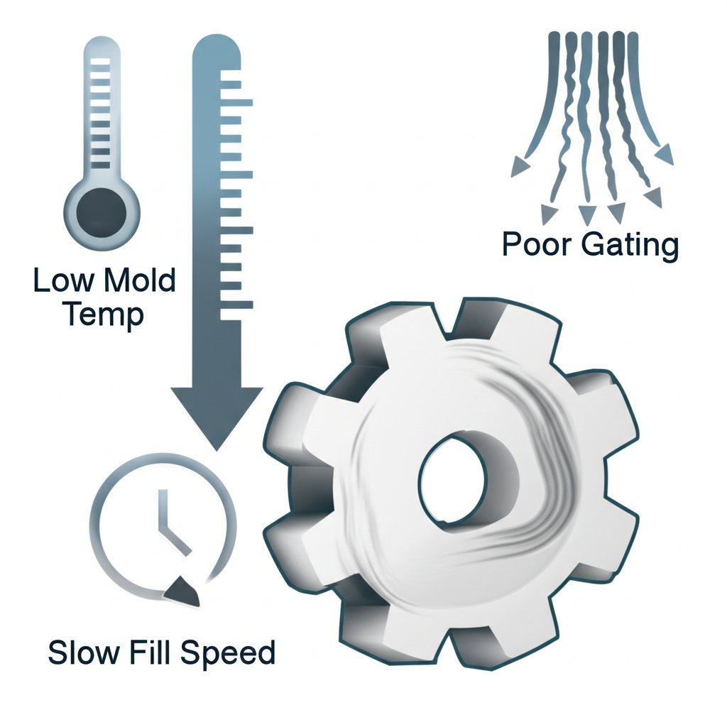
Flow marks on die cast surfaces are visible lines, streaks, or patterns that indicate an inconsistent flow of molten metal during the mold filling process. They are primarily caused by premature solidification due to factors like low mold temperature, improper filling speed, or flawed mold design. Resolving these defects involves a systematic adjustment of process parameters, optimizing mold temperature, and refining the gating system to ensure a smooth, uniform fill of the mold cavity.
Understanding Flow Marks: Definition and Visual Identification
In the die casting process, achieving a flawless surface finish is a primary goal. However, various defects can arise, with flow marks being one of the most common. Flow marks, sometimes called flow lines, are surface imperfections that appear as non-directional lines, streaks, or veins. These patterns, which can resemble a geographical map, trace the path the molten metal took as it filled the mold cavity. While they are typically surface-level defects, they are often visible and can be felt by hand, indicating an irregularity in the casting's skin.
The formation of flow marks is a matter of thermal dynamics and fluid mechanics. They occur when different streams of molten metal within the mold fail to merge perfectly. This happens because a portion of the liquid metal solidifies prematurely while the rest is still flowing. As the still-molten metal flows over these partially solidified sections, it creates imperfect joints and visible lines on the surface. These are not cracks but rather evidence of a turbulent or interrupted filling process where the metal fronts did not fuse seamlessly.
Visually identifying flow marks is the first step in diagnosing the problem. Quality control technicians look for specific characteristics to distinguish them from other defects. Key visual indicators include:
- Streaks or Lines: The most common appearance is of smooth, slightly wavy lines that are distinct from the base metal's texture.
- Non-Directional Patterns: Unlike a scratch, which has a clear direction, flow marks often appear as swirling or meandering patterns.
- Color Variation: The marks may have a slightly different shade or gloss level compared to the surrounding surface.
- Location: They often appear around the gate or where multiple streams of molten metal converge.
It is important to differentiate flow marks from other defects like heat checking. Heat check marks are fine surface cracks on the casting caused by thermal fatigue in the die itself, not by issues with the metal flow during a single cycle. Understanding these distinctions is crucial for applying the correct remedial actions.
The Root Causes of Flow Marks in Die Casting
Flow marks are not caused by a single issue but rather a combination of factors related to process parameters, mold design, and material handling. A thorough diagnosis requires examining the entire die casting process. The primary culprits stem from conditions that promote premature or uneven cooling of the molten alloy as it fills the mold cavity.
One of the most significant factors is temperature—both of the mold and the molten metal. A low mold temperature is a frequent cause; for instance, a temperature below 180°C for aluminum alloys or 90°C for zinc alloys can cause the metal to chill too quickly upon contact with the die walls. Similarly, if the molten metal itself is not at an optimal temperature, its viscosity increases, hindering a smooth flow and preventing separate fronts from merging properly. This leads to the characteristic streaks and lines on the final part.
The dynamics of how the metal is injected into the mold are equally critical. An incorrect filling speed can disrupt the process. If the speed is too slow, the metal has too much time to cool before the cavity is full, leading to cold shuts and flow marks. Conversely, if the speed is too high, it can cause turbulence, trapping air and preventing a laminar flow, which also results in surface defects. The goal is to fill the cavity as quickly as possible without introducing turbulence, a delicate balance that requires precise control.
Beyond process parameters, the physical design of the mold and its components plays a foundational role. A poorly designed gating and runner system is a common source of flow problems. Gates that are too small or improperly positioned can restrict flow or create jets, while sharp corners in the runner system can cause turbulence. Furthermore, inadequate venting prevents trapped air and gases from escaping the cavity as the metal enters. This trapped air acts as a barrier, disrupting the metal's flow path and leading to imperfections on the surface. Finally, the application of mold release agents or coatings must be managed carefully. An excessive or unevenly applied coating can interfere with the metal's flow and affect the surface temperature of the die, contributing to the formation of flow marks.
Proven Solutions and Prevention Strategies
Effectively eliminating flow marks requires a systematic approach that addresses the root causes identified in the diagnostic phase. The solutions involve adjusting process parameters, making potential mold modifications, and implementing preventative design strategies. The most immediate and often effective changes are made to the machine's settings.
The first line of defense is optimizing temperatures. Increasing the mold temperature ensures that the molten metal remains fluid longer, allowing different flow fronts to merge seamlessly before solidification. As recommended by sources like Minghe Casting, maintaining temperatures above 180°C for aluminum and within the 90-150°C range for zinc is a good starting point. Adjusting the molten metal temperature can also improve fluidity. Alongside temperature, optimizing the filling speed is crucial. This involves finding the right injection speed to ensure the cavity fills completely before any part of the metal solidifies, without causing excessive turbulence. Fine-tuning these parameters is often an iterative process to find the optimal balance for a specific part and mold.
If adjusting process parameters is insufficient, the focus must shift to the mold itself. The design of the gating system is paramount. This may involve adjusting the cross-sectional area or position of the gate to improve the flow state of the metal as it enters the cavity. Expanding overflow grooves and improving vents can also provide a path for trapped air and cooler metal to escape, ensuring a more uniform fill. Additionally, the application of mold release agents should be carefully controlled to be thin and uniform, preventing any interference with the metal's flow. The following table summarizes a problem-solution approach:
| Problem (Cause) | Solution / Strategy |
|---|---|
| Low Mold Temperature | Increase mold surface temperature (e.g., above 180°C for aluminum, within 90-150°C for zinc). |
| Incorrect Filling Speed | Adjust injection speed to fill the cavity quickly but without turbulence. |
| Poor Gating/Runner Design | Modify gate size, shape, and location to promote laminar flow. |
| Inadequate Venting | Add or enlarge vents and overflow wells to allow trapped air to escape. |
| Excessive Mold Coating | Apply a thin, uniform layer of release agent. |
For long-term prevention, especially during the development of new parts, modern technology offers powerful tools. Using mold flow simulation software during the design phase is a highly effective preventative measure. As noted by experts at Bruschi, these programs can predict how the metal will flow through the mold, identifying potential problem areas where flow marks might occur before any steel is cut. This allows engineers to optimize the gating, runner, and cooling systems virtually, saving significant time and cost by preventing defects from the outset.
Impact of Mold Design and Material Choice on Flow Marks
While operators can adjust process parameters on the factory floor, the most robust solutions for preventing flow marks are often embedded in the initial design of the mold and the selection of the casting alloy. These foundational elements dictate the fundamental conditions under which the molten metal flows and solidifies, making them critical for achieving high-quality surface finishes consistently.
A well-engineered mold is the cornerstone of a defect-free casting. The gating system—which includes the sprue, runners, and gates—must be designed to deliver molten metal to the cavity in a controlled, non-turbulent manner. Best practices in mold design, as highlighted by resources like Prototool, emphasize smooth transitions, appropriately sized channels, and gate locations that promote a uniform filling pattern. Equally important is the venting and overflow system. Vents are small channels that allow air trapped in the cavity to escape as the metal enters. Without adequate venting, this trapped air can cause back pressure, disrupting the flow and leading to defects like flow marks and porosity.
Material selection also plays a subtle but important role. Different die-casting alloys, such as zinc (Zamak) versus aluminum (e.g., A380), have distinct thermal and flow characteristics. Zinc alloys generally have lower melting points and higher fluidity, which can make them more forgiving in certain situations. However, each alloy has its own ideal range for casting temperature, pressure, and speed. Understanding these properties is essential for tailoring both the mold design and the process parameters to prevent flow-related defects. The alloy's chemistry, including its silicon or magnesium content, can also affect its solidification behavior and susceptibility to certain defects.
Ultimately, preventing surface defects is about precision engineering from start to finish. This principle extends beyond die casting to other high-performance manufacturing methods. For instance, in the world of automotive components, processes like hot forging also demand meticulous control over material flow to ensure structural integrity and flawless surfaces. Companies that specialize in precision manufacturing, such as Shaoyi (Ningbo) Metal Technology, build their reputation on mastering these complex processes for critical applications like automotive forging parts, where quality is non-negotiable. The use of advanced simulation, in-house die design, and rigorous quality control are hallmarks of a commitment to producing defect-free components, whether they are cast or forged.
Frequently Asked Questions
1. What are the heat check marks in die casting?
Heat check marks are fine, web-like cracks that appear on the surface of a die-cast part. Unlike flow marks, which are caused by issues with molten metal flow in a single shot, heat checking is a result of thermal fatigue in the die steel itself. Over many cycles of heating and cooling, the surface of the mold develops cracks, which are then transferred to the surface of every part cast from it. It is a sign of die wear, not a process parameter issue.
2. How to solve flow marks in injection molding?
While this article focuses on die casting, flow marks also occur in plastic injection molding for similar reasons. The solutions are conceptually parallel: increase the temperature of the mold and the molten plastic to improve flow, optimize the injection speed and pressure to ensure the mold fills evenly, and modify the mold design by enlarging gates or runners. Increasing back pressure can also help ensure the material is packed uniformly, preventing flow-related defects.