 Small batches, high standards. Our rapid prototyping service makes validation faster and easier —

Essential Strategies for Preventing Cracks in Die Cast Parts

TL;DR
Preventing cracks in die cast components requires a comprehensive strategy focused on managing thermal stress, optimizing design, and ensuring material purity. The primary causes of cracks are rapid or uneven cooling, poor mold and part design featuring stress concentrators like sharp corners, and the use of contaminated metal alloys. Effective prevention involves controlling cooling rates, preheating molds, designing parts with uniform wall thickness and rounded corners, and using high-quality, clean alloys.
Understanding Die Casting Cracks: Types and Causes
Cracks are fractures or separations on the surface or interior of a die cast part, compromising its structural integrity and performance. These defects arise from stresses that exceed the material's strength during or after the solidification process. Understanding the different types of cracks is the first step toward effective diagnosis and prevention. The most common culprits are thermal stress from improper temperature management, stress concentrations due to design flaws, and weaknesses introduced by material impurities.
There are several distinct types of cracks, each with a unique cause and time of formation. Hot cracks, also known as hot tears, occur at high temperatures while the metal is still in a semi-solid state. They are often caused by thermal stress and impurities that create weak points along the grain boundaries of the material. In contrast, cold cracks develop after the casting has fully solidified and cooled. These are typically the result of residual stress from contraction, uneven cooling, or external forces during ejection from the mold. Other common types include thermal fatigue cracks, which result from repeated heating and cooling cycles during the part's service life, and shrinkage cracks, caused by uneven solidification in areas with varying wall thickness.
A thorough analysis of the root cause is essential for implementing the correct solution. For instance, according to an article from diecasting-mould.com, high-stress levels, thermal stresses, and material impurities are major contributors to cracks in aluminum die castings. A poor mold design with sharp corners or abrupt changes in wall thickness can create stress concentration points where cracks are likely to initiate. Similarly, impurities in the aluminum alloy can act as nucleation sites for fractures, significantly reducing the component's durability.
| Crack Type | Appearance | Time of Formation | Primary Cause |
|---|---|---|---|
| Hot Cracks (Hot Tears) | Irregular, jagged lines, often following grain boundaries | During solidification (high temperature) | Thermal stress, alloy impurities, hindered contraction |
| Cold Cracks | Clean, linear fractures | After solidification (room temperature) | Residual stress, uneven cooling, ejection stress |
| Thermal Fatigue Cracks | Network of fine cracks (crazing), often elongated | During the component's service life | Repeated thermal cycling (expansion & contraction) |
| Shrinkage Cracks | Occur in thick sections or at junctions | During cooling and solidification | Differential shrinkage due to uneven cooling rates |
Proactive Prevention: Optimizing Mold Design and Material Selection
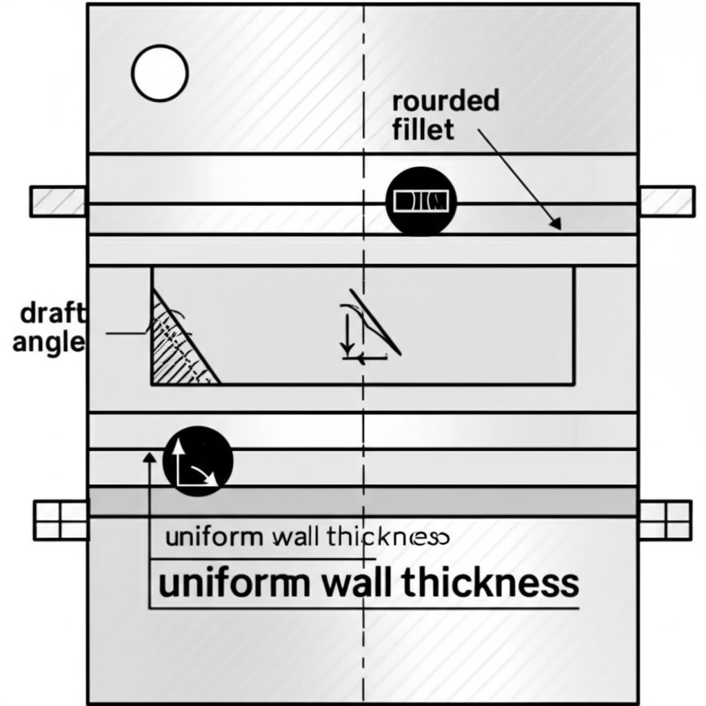
The most effective strategy for preventing cracks is to address potential issues before the casting process even begins. Intelligent mold design and careful material selection form the foundation of a robust, defect-free manufacturing process. As noted by experts at Prototool, minimizing sharp angles, ensuring sufficient fillets, and providing adequate draft angles are critical design considerations to prevent stress concentration. Flaws in the mold's geometry can directly translate into weaknesses in the final component, making design a crucial first line of defense.
Material selection for both the component and the mold is equally important. Using high-purity alloys free from contaminants like hydrogen gas or non-metallic inclusions is essential to avoid creating weak points within the casting. CEX Casting emphasizes that impurities, whether from raw materials or the melting process, can develop into cracks under stress. For the mold itself, using high-grade hot work mold steels like 1.2344 (H13) can improve durability and resistance to thermal fatigue. The goal is to create a system where both the tool and the material are optimized for thermal stability and mechanical strength.
Precision manufacturing is key to producing high-integrity components. Companies like Shaoyi (Ningbo) Metal Technology, which specialize in high-performance automotive forging parts, exemplify the rigorous quality control and material science principles that are also vital in die casting. This focus on excellence from the initial design and material stages helps ensure the final product meets stringent performance standards.
To minimize crack risk during the design phase, engineers should adhere to a set of best practices. These guidelines help distribute stress evenly and promote uniform solidification, directly countering the primary causes of cracks.
- Ensure Uniform Wall Thickness: Avoid abrupt changes in section thickness to promote even cooling and reduce the risk of shrinkage-related stress.
- Use Generous Fillets and Radii: Sharp internal corners are major stress concentrators. Incorporate smooth, rounded fillets to distribute stress over a wider area.
- Incorporate Adequate Draft Angles: Proper draft angles make it easier to eject the part from the mold, reducing the mechanical stress that can cause cold cracks.
- Optimize Gating and Cooling Systems: Design gating systems for smooth metal flow and cooling channels to ensure uniform temperature distribution across the mold, preventing hot spots and thermal gradients.
- Select High-Quality Materials: Choose high-purity alloys and robust mold steels (e.g., 1.2343, 1.2344/H13) to ensure both the part and the tool can withstand the process stresses.
Mastering the Process: Controlling Temperature, Cooling, and Injection
Once the design and materials are optimized, precise control over the casting process itself is critical to prevent cracks. Thermal management is arguably the most important factor, as rapid temperature changes are a primary source of stress. As highlighted in the featured snippet and multiple sources, controlling the temperature and cooling rate is crucial for uniform solidification. Starting production with a cold mold can cause severe thermal shock. Therefore, preheating the mold to an optimal operating temperature (typically 180°C to 280°C) before the first injection is a non-negotiable step to minimize thermal stress.
The rate at which the casting cools must be carefully managed. An optimized cooling rate allows the entire part to solidify uniformly, preventing the outer layers from solidifying too quickly while the core remains molten. This balance prevents the buildup of internal stresses that lead to both hot and cold cracks. As Dynacast points out, enhancing thermal management is a key solution to minimizing cracks. This involves not just preheating but also the strategic use of cooling channels and controlled spraying of release agents to maintain thermal equilibrium throughout the production cycle.
Injection parameters, including speed and pressure, also play a significant role. Injecting molten metal too quickly can cause turbulence, trapping gas and leading to porosity, which can become a crack initiation site. According to Prototool, keeping the gate filling speed within a range of 30-50m/s is beneficial for mold life and part quality. The pressure applied during and after injection must also be sufficient to feed molten metal into shrinking areas, but excessive pressure can stress the mold. Proper control over these variables ensures a smooth, complete fill without introducing unnecessary stress into the system.
| Parameter | Objective | Common Pitfall |
|---|---|---|
| Mold Temperature | Maintain stable thermal equilibrium to prevent thermal shock. | Starting with a cold mold or uneven heating. |
| Cooling Rate | Ensure uniform solidification and minimize residual stress. | Cooling too rapidly or unevenly, creating thermal gradients. |
| Injection Speed | Achieve a smooth, complete fill without turbulence. | Excessive speed causing gas entrapment and mold erosion. |
| Injection Pressure | Ensure dense casting and feed shrinkage porosity. | Insufficient pressure leading to porosity or excessive pressure stressing the mold. |
Cold Mold Startup Procedure
A disciplined startup process is essential to avoid damaging the mold and producing defective parts. Follow these steps to bring a cold mold to operating temperature safely:
- Preheat the Mold: Use a mold temperature controller or oil heater to gradually bring the mold to the recommended starting temperature before closing it in the machine.
- Initial Low-Pressure Cycles: Run 5-10 injection cycles at a low pressure and low speed. This allows the molten metal to gently heat the mold surfaces, further stabilizing its temperature.
- Monitor and Adjust: Carefully monitor the mold temperature and the quality of the first few parts. Make gradual adjustments to cooling and injection parameters as the system reaches thermal equilibrium.
- Begin Full Production: Only initiate high-speed, high-pressure production once the mold temperature is stable and parts are free from flow marks and other thermal-related defects.

Achieving Defect-Free Production
Preventing cracks in die cast components is not about a single solution but a holistic approach that integrates intelligent design, superior materials, and precise process control. By understanding the fundamental causes of hot and cold cracks—primarily thermal stress and stress concentration—engineers can implement proactive strategies. Key takeaways include the importance of designing parts with uniform thickness and generous radii, selecting high-purity alloys, and meticulously managing thermal conditions through mold preheating and controlled cooling.
Ultimately, achieving zero-defect die casting relies on a commitment to quality at every stage. From the initial part design to the final process parameter adjustment, each step plays a crucial role in mitigating the risks of cracking. By following these best practices, manufacturers can enhance component reliability, reduce scrap rates, and deliver high-performance parts that meet the most demanding specifications.
Frequently Asked Questions
1. How can cracks in casting be avoided?
Cracks can be avoided by ensuring uniform cooling to minimize thermal stress, optimizing part and mold design to eliminate stress concentrators like sharp corners, using high-quality and pure alloys, and controlling process parameters like injection speed and mold temperature. Preheating molds and ensuring a balanced ejection system are also critical steps.
2. Why does cast metal crack?
Cast metal cracks primarily due to stress that exceeds its strength during or after solidification. This stress can be thermal (from uneven or rapid cooling), mechanical (from the ejection process or external forces), or residual (locked into the part as it cools and shrinks). Impurities in the metal and poor part design can create weak spots where cracks are more likely to form.
3. How do you stop metal from cracking?
To stop metal from cracking during casting, you must manage the sources of stress. This involves controlling the cooling rate to be slow and uniform, preheating the mold to reduce thermal shock, designing parts to avoid sharp angles and sudden changes in thickness, and using clean, high-grade alloys. Ensuring the casting can contract freely without being constrained by the mold is also important.
4. What is the reason for the die block to crack during the forming process?
A die block (the mold itself) can crack due to thermal fatigue from repeated cycles of heating and cooling. This is often accelerated by shooting molten metal into a cold mold, causing severe thermal shock. Other causes include stress concentration from sharp corners in the mold cavity design, improper heat treatment of the die steel, and mechanical stress from high injection pressures.