 Small batches, high standards. Our rapid prototyping service makes validation faster and easier —

Essential Forging Design for Automotive Engineers

TL;DR
A forging design guide for automotive engineers focuses on creating high-strength, durable, and manufacturable metal components through controlled deformation. Success hinges on mastering several key design considerations: establishing appropriate draft angles for easy part removal from the die, defining generous fillet and corner radii to ensure proper metal flow and prevent defects, and selecting the right material—like high-strength steel or lightweight aluminum—to meet performance requirements. Adhering to these principles is essential for producing reliable and cost-effective automotive parts.
Fundamentals of Forging in Automotive Engineering
Forging is a manufacturing process where metal is shaped by localized compressive forces, delivered by hammering, pressing, or rolling. Unlike casting, which involves pouring molten metal into a mold, forging refines the metal's internal grain structure, aligning it with the part's geometry. This process, often performed at elevated temperatures (hot forging), significantly enhances the component's strength, ductility, and fatigue resistance. This makes it an indispensable technique in the automotive industry, where reliability and performance under stress are paramount.
In automotive applications, forging is the process of choice for critical components subjected to high stress and shock loads. Parts like crankshafts, connecting rods, suspension components, and transmission gears are frequently forged. The refined grain flow achieved through forging creates parts that are stronger and more reliable than their cast or machined counterparts. This inherent strength allows for the design of lighter parts without compromising on safety or durability, a crucial factor in improving vehicle fuel efficiency and performance. A design-first approach is vital to leverage these benefits fully.
A well-executed forging design not only guarantees superior mechanical properties but also optimizes the entire manufacturing workflow for cost-effectiveness. By considering the forging process during the initial design phase, engineers can minimize material waste, reduce the need for secondary machining operations, and extend the life of the forging dies. This proactive approach, known as Design for Manufacturability (DFM), ensures that the final component is not only strong and reliable but also economically viable to produce at scale.
Key Design Considerations for Manufacturability (DFM)
At the core of effective forging is a deep understanding of Design for Manufacturability (DFM) principles. These guidelines ensure that a component can be produced efficiently, consistently, and economically. For automotive engineers, mastering these considerations is crucial for translating a digital design into a high-performance physical part.
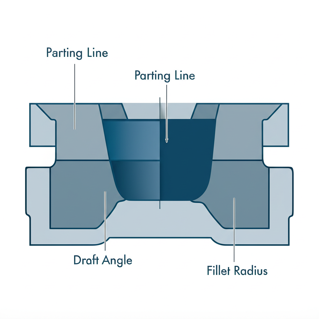
Parting Line
The parting line is the plane where the two halves of the forging die meet. Its placement is one of the most critical decisions in forging design, as it affects metal flow, die complexity, and the final part's grain structure. A well-placed parting line simplifies the die, minimizes flash (excess material squeezed out of the die), and avoids undercuts. Ideally, the parting line should be placed at the largest cross-section of the component to allow for easier metal flow and part removal.
Draft Angles
A draft angle is a slight taper applied to the vertical surfaces of a forging. Its primary purpose is to facilitate the removal of the part from the die after it has been formed. Without adequate draft, the part can stick, leading to damage to both the component and the expensive die. Standard draft angles for steel forgings typically range from 3 to 7 degrees, though the exact angle depends on the part's complexity and the depth of the die cavity. Insufficient draft is a common design flaw that can halt production and increase costs significantly.
Fillet and Corner Radii
Sharp internal and external corners are detrimental to the forging process. Generous fillet (internal) and corner (external) radii are essential for several reasons. They promote smooth metal flow into all parts of the die cavity, preventing defects like laps or cold shuts where metal folds over on itself. Radii also help reduce stress concentrations in the final part, enhancing its fatigue resistance and overall durability. Furthermore, rounded corners in the die are less prone to wear and cracking, which extends the tool's lifespan.
Ribs, Webs, and Pockets
Ribs are thin protrusions used to add strength, while webs are the thin sections of metal connecting other parts of the forging. When designing these features, it's important to keep them short and wide to facilitate metal flow. Tall, thin ribs can be difficult to fill completely and may cool too quickly, leading to defects. Similarly, deep pockets should be avoided as they can trap material and require excessive forging pressure. A good rule of thumb is to make the height of a rib no more than six times its thickness.
Tolerances and Machining Allowances
Forging is a near-net-shape process, but it cannot achieve the tight tolerances of machining. Designers must specify realistic tolerances that account for the inherent variations in the process, such as die wear and thermal contraction. An extra layer of material, known as a machining allowance, is often added to surfaces that require a precise finish. This ensures there is sufficient stock for subsequent CNC machining operations to bring the part to its final dimensions without issue.
Material Selection and Its Impact on Design
The choice of material is a foundational decision in forging design that directly influences a component's mechanical properties, weight, cost, and manufacturing process. In the automotive sector, materials must be selected to withstand demanding operational conditions, including high stress, extreme temperatures, and potential corrosion. The properties of the chosen material will dictate several design parameters, from wall thickness to the required radii.
Common materials in automotive forging include various grades of steel, aluminum alloys, and occasionally titanium for high-performance applications. Steel, known for its exceptional strength and toughness, is used for components like crankshafts and gears. Aluminum offers a lightweight alternative with excellent corrosion resistance, making it ideal for suspension parts and engine mounts where weight reduction is a priority. The decision between these materials involves a trade-off between strength, weight, and cost.
The selected material's forgeability—its ability to be shaped without cracking—is a critical factor that affects the design. For example, some high-strength steel alloys are less ductile and require more generous fillet radii and larger draft angles to ensure proper material flow within the die. Aluminum, while lighter, has different thermal properties and may require adjustments to the forging temperature and pressure. A comparison of common forging materials is outlined below:
| Material | Key Properties | Common Automotive Applications | Design Implications |
|---|---|---|---|
| Carbon Steel | High strength, good toughness, cost-effective | Crankshafts, connecting rods, axles | Requires careful heat treatment; less corrosion resistant |
| Alloy Steel | Excellent strength-to-weight ratio, wear resistance | Gears, bearings, high-stress components | May require higher forging pressures and specific thermal cycles |
| Aluminum Alloys | Lightweight, high corrosion resistance, good thermal conductivity | Suspension components, control arms, wheels | Requires larger radii; lower strength than steel |
| Titanium Alloys | Very high strength-to-weight ratio, superior corrosion resistance | Exotic performance parts (e.g., valves, connecting rods in racing) | Expensive; difficult to forge, requiring higher temperatures |
Ultimately, material selection is a collaborative process between the design engineer and the forging supplier. Early consultation ensures that the chosen alloy not only meets the performance requirements of the final application but is also compatible with an efficient and cost-effective forging process.

From CAD to Component: Tooling and Process Integration
The transition from a digital design to a physical forged component is a complex process where design choices directly impact the manufacturing tooling and workflow. Modern automotive engineering relies heavily on Computer-Aided Design (CAD) and Computer-Aided Engineering (CAE) software to model parts and simulate the forging process. These tools allow engineers to perform Finite Element Analysis (FEA) to predict metal flow, identify potential stress concentrations, and optimize the design before any physical tooling is made. This digital validation can reduce the risk of failure by up to 40%, preventing costly errors and delays.
The design of the forging dies is a direct reflection of the part's geometry. Every design consideration—from the parting line and draft angles to fillet radii—is machined into hardened tool steel to create the die cavity. The complexity of the part dictates the complexity of the die, which in turn affects cost and lead time. Simple, symmetrical parts with generous drafts and radii require simpler, more durable dies. Conversely, complex geometries may necessitate multi-part dies or additional forging steps, increasing both cost and the potential for wear.
Integrating the design with the capabilities of the forging supplier is crucial for success. For robust and reliable automotive components, specialized partners can offer invaluable expertise. For example, Shaoyi Metal Technology specializes in high-quality, IATF16949 certified hot forging for the automotive industry, offering everything from in-house die manufacturing to full-scale production. Engaging with such experts early in the design process ensures that the component is optimized not just for performance, but for efficient, large-scale production, leveraging their knowledge of tooling, material behavior, and process control to achieve the best possible outcome.
Best Practices and Common Design Pitfalls to Avoid
Adhering to established best practices while avoiding common mistakes is the final step in mastering forging design. A well-designed part not only performs better but is also easier and more economical to manufacture. This section summarizes the key principles to follow and the pitfalls to steer clear of during the design process.
Key Best Practices
- Simplify Geometry: Whenever possible, opt for simple, symmetrical shapes. This promotes uniform metal flow, simplifies die design, and reduces the likelihood of defects.
- Ensure Uniform Thickness: Strive for consistent cross-sectional thickness throughout the part. This helps ensure even cooling, minimizing the risk of warping and residual stress.
- Use Generous Radii: Always incorporate large fillet and corner radii. This is crucial for facilitating material flow, reducing stress concentrations, and extending the life of the forging dies.
- Specify Appropriate Draft: Apply adequate draft angles (typically 3-7 degrees) to all surfaces parallel to the direction of die movement to ensure easy part removal.
- Consult Your Forging Partner Early: Engage with your forging supplier during the initial design phase. Their expertise can help you optimize the design for manufacturability, saving time and money.
Common Pitfalls to Avoid
- Designing Sharp Corners: Sharp internal or external corners are a primary source of stress concentration and can lead to cracking in the part or the die. They also impede metal flow.
- Including Undercuts: Undercuts are features that prevent the part from being removed from a simple two-part die. They drastically increase tooling complexity and cost and should be avoided or designed to be machined in a secondary operation.
- Specifying Unnecessarily Tight Tolerances: Forging is a near-net-shape process. Demanding tolerances that are tighter than the process can naturally hold will require costly secondary machining operations.
- Creating Thin, Deep Ribs or Pockets: Tall, thin ribs and deep, narrow pockets are difficult to fill with material during the forging process and can lead to incomplete parts or defects.
- Ignoring the Parting Line: Poor placement of the parting line can lead to complex and expensive tooling, excessive flash, and unfavorable grain flow, compromising the part's integrity.